Table of Contents
Advertisement
OPERATOR'S MANUAL
®
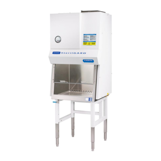
SterilGARD
Class II, Type A2
Biosafety Cabinet
MODEL
SG303, SG303-INT, SG303-JPN, SG303-AUS
Revision
Date
Description
F
3/25/15
Updated branding.and split manuals
This manual includes information for installation, operation, maintenance and spare parts. We
recommend that it be kept near the cabinet for ready reference
Advertisement
Table of Contents

Related Manuals for Baker SterilGARD SG303


Summary of Contents for Baker SterilGARD SG303
- Page 1 OPERATOR’S MANUAL ® SterilGARD Class II, Type A2 Biosafety Cabinet MODEL SG303, SG303-INT, SG303-JPN, SG303-AUS Revision Date Description 3/25/15 Updated branding.and split manuals This manual includes information for installation, operation, maintenance and spare parts. We recommend that it be kept near the cabinet for ready reference...
- Page 2 INTRODUCTION AND WELCOME It is a pleasure to welcome you to the growing number of customers who own and operate Baker biological safety cabinets. As the inventors of the laminar flow biological safety cabinet and the leaders in the field, Baker people take special pride in providing a cabinet that is designed for maximum performance.
-
Page 3: Table Of Contents
TABLE OF CONTENTS I - FUNCTION AND DESCRIPTION OF THE STERILGARD III ADVANCE ........ 3 AIRFLOW INSIDE THE BIOLOGICAL SAFETY CABINET ............... 3 Fig. 1 Airflow Inside the Cabinet ............................. 3 POSITIVE AND NEGATIVE PRESSURE AREAS ..................4 ACCESS TO THE WORK AREA ........................4 DESIGN DETAILS .............................. - Page 4 DECONTAMINATION ............................17 CLEANING AND DISINFECTING STAINLESS STEEL ................18 Simple Cleaning ................................18 Disinfection ..................................19 USING ANCILLARY EQUIPMENT ........................ 19 ABOUT THE HEPA FILTERS .......................... 19 REMINDERS ............................... 20 IV - ON-SITE CHECKS AND MAINTENANCE PROCEDURES ............21 THE AIRFLOW BALANCE ..........................
-
Page 5: I - Function And Description Of The Sterilgard Iii Advance
The SterilGARD III Advance cabinet features The Baker Company's momentum air curtain. See Figure 1. The stainless steel metal diffuser just below the supply HEPA filter creates a faster airflow behind the sash than over the work zone. The faster airflow in front makes an extremely effective air barrier. -
Page 6: Positive And Negative Pressure Areas
Cabinet Use for how to use the viewscreen correctly while the cabinet is in use). As with other Baker cabinets, the GFCI protected electrical outlets inside the work area are protected by a separate circuit breaker so that an electrical overload by ancillary equipment won’t affect air handling. -
Page 7: Motor/ Blower Capacity
incorporated into the design to improve ergonomics so the operator can use the cabinet properly without sacrificing comfort or safety. Motor/ blower capacity A motor/blower's capacity is measured by its ability to provide a nearly constant volume of air as resistance increases because of filter loading. -
Page 8: Work Area Lighting
Work area lighting The work area is illuminated by two external fluorescent lamps which provide a minimum of 100 foot- candles of light at the work surface. Drain Pan The drain pan is designed with 7/16” radius in all four bottom corners to facilitate cleaning and disinfection. -
Page 9: Solid-State Electronic Ballast
Note: instructions on assembling and installing the stand are packed in the cardboard box with the stand. Solid-state electronic ballast The SterilGARD III Advance features solid-state electronic ballasts for fluorescent and optional UV light. These ballasts increase reliability, efficiency, service life and reduce heat. Programmable Logic Controller ... -
Page 10: Ultraviolet Germicidal Lamp (Optional)
With the optional stand, the cabinet weight is 457 pounds with a shipping weight of 594 pounds. Electrical Specifications 115 VAC, 20A, 1 Phase, 60 Hz incorporates Baker’s StediVOLT SterilGARD III Advance motor speed controller for the blower motor. This compensates for minor variations in incoming line voltages. ... -
Page 11: Environmental Conditions
If any concealed damage is found it should be reported to the delivering carrier. A claim for restitution should be filed within 15 days. Due to the risk of mishandling by trucking companies, The Baker Company has removed certain parts of the cabinet and packed them separately. -
Page 12: Location Within The Laboratory
Published research from The Baker Company and unpublished tests performed at the National Cancer Institute show that if a draft or other disruptive air current were to exceed the intake velocity of the cabinet, contamination can enter the work area or escape from it (for more information, contact Baker). -
Page 13: Connecting The Exhaust
7. If ordered with the optional stand, refer to the stand installation and assembly instructions packed in the cardboard box with the stand. NOTE: If you place your unit on the optional stand and you need to move the unit, we recommend you leave the unit on the stand. -
Page 14: Final Connections And Tests
The transition adds approximately 0.1” w.c. resistance to the system. For more details, please contact The Baker Company. While the cabinet contains a damper to adjust for variations in filter resistance and sash opening size, the building exhaust system should contain provisions to adjust the building system flow and pressure. - Page 15 FOR MORE INFORMATION For a complete listing of articles, papers and reports related to containment, clean air products and safety, contact The Baker Company for our complete Bibliography or visit our website at www.bakerco.com...
-
Page 16: Iii Proper Cabinet Use
In order to keep the interior workspace clean and free of particulates, all Baker biosafety cabinets are designed for continuous operation. If the blower is turned off, the unit becomes contaminated with room air. -
Page 17: Start-Up Procedure
The yellow indicator light below the switch will light when the UV light is turned on. This unit is also capable of regulating the amount of time the UV light stays on which is determined by the operator. This function is very useful if the cabinet is to be left unattended for an extended period of time. -
Page 18: Working In The Cabinet
passes in or out through the air barrier, until the procedure is completed. Implements should be arranged in the cabinet's work area in logical order so that clean and dirty materials are segregated, preferably on opposite sides of the work area. Blocking the front and rear perforated grilles must be avoided. -
Page 19: Reacting To Spills
with no activity so that the airborne contaminants will be purged from the work area. Next, make sure that all equipment is removed from the cabinet. 10. After you have removed all materials, culture apparatus, etc., decontamination of the interior surfaces should be repeated. -
Page 20: Cleaning And Disinfecting Stainless Steel
The inside cabinet work space should be at room temperature with 60% to 85% relative humidity. If relative humidity is low (10 to 30%) add a pan of boiling water on the work surface. If it is (40% to 55%) add a pan of hot tap water on the work surface. Relatively humidity above 85% will require extra clean up which will be covered in Step 15. -
Page 21: Disinfection
Iron rust discoloration can be treated by rubbing the surface with a solution of 15% to 20% by volume of Nitric Acid and water and letting it stand for one to two minutes to loosen the rust. Disinfection The purpose of disinfection is to destroy particular organisms that could pose a potential hazard to humans or compromise the integrity of the experiment. -
Page 22: Reminders
It is very delicate and the filter media should never be touched. Proven efficiency in all HEPA filters used in Baker cabinets is 99.99% for particles 0.3 microns in diameter. The 0.3 micron particle is used as the basis for filter definition because theoretical studies have shown that filtration efficiency should be at a minimum for particles of this diameter, with efficiency increasing for particles either larger or smaller. -
Page 23: On-Site Checks And Maintenance Procedures
Our representatives can tell you about other tests, which you may consider desirable. As reported earlier in this manual, each individual cabinet made by The Baker Company is carefully tested before it leaves the factory. Your copy of the test report, which you will find at the back of this manual, ... -
Page 24: Filter Leak Test
When the light canopy is lowered, some electrical parts are exposed. Do not perform any work inside the canopy unless you are a trained electrician or electronic technician. 5. Make adjustments to the blower speed controller and the damper as necessary. The speed controller is located inside the light canopy. -
Page 25: Airflow Smoke Pattern Test
Warning! Decontaminate the unit before measuring the upstream concentration of aerosol in a contaminated plenum. 3. Perform filter leak test per NSF 49. 4. Repair leaks as required. Airflow Smoke Pattern Test We recommend that qualified technicians verify the direction of airflow within your cabinet before the cabinet is used. -
Page 26: Electrical Safety Tests
Electrical Safety Tests The electrical leakage, ground circuit resistance and polarity were tested at our factory before shipment to ensure that there is no risk of electrical shock present in your cabinet. Since electrical components may become damaged in transport, we recommend qualified technicians retest them, before the cabinet is used. The electrical safety tests should also be performed at prescribed intervals as specified by an industrial hygienist, safety officer or other qualified person. -
Page 27: Replacing The Hepa Filters
Replacing the HEPA Filters When the certifier can no longer set the cabinet air flows to within 5 FPM of the nominal set point by adjusting the speed control or the damper, the filters must be replaced. If the filters are damaged, they will also need to be replaced. -
Page 28: Figure 3 – Downflow Plenum
Loosen each of the eight 3/8” hex head bolts on the front seal panel. Be sure not to damage or lose the seal washers on each bolt. Remove the front seal panel making sure that you do not damage the gasket. The filters are now exposed. -
Page 29: Troubleshooting
Replace the filter(s) by simply aligning them with the notches in the frame of the plenum and sliding them back against stops in rear, ensuring that the gasket remains attached on both sides. The exhaust plenum clamps should be tightened first, alternately two to three revolutions ”. - Page 30 Check to make sure the unit is plugged into a dedicated electrical outlet (grounded 20 amp, 115 Volt AC, 60Hz). Check to make sure the wiring connections inside the left end of the light canopy are pushed together properly. ...
- Page 31 button. The indicator will continue to flash until the window is set in the correct position. After 5 minutes, the alarm will sound again. You may press the alarm-reset button again. If the fluorescent light does not work - The blower switch should be turned on and the yellow indicator below the switch should be lit.
-
Page 32: Sg303 Disassembly Instructions
Sg303 Disassembly Instructions NOTES: Refer to Figure 3 – Downflow Plenum for blower, filter and plenum configuration. For Motor/Blower removal, follow steps 1-18. For filter removal, follow steps 1-15 & 21-23. TOOLS REQUIRED: (1) 3/8” spin wrench, (2) 3/8” socket and drill, (3) ¾” wrench and (4) ¼” spin wrench DISASSEMBLY: 1. - Page 33 23. Pull exhaust filter straight out towards you. 24. Remove the side panels - (7) retaining bolts per side. 25. Loosen the bolts on the inside of the exhaust plenum enough to allow the clamping hardware to angle out away from the slotted retaining brackets. 26.
-
Page 34: Appendix
APPENDIX... -
Page 35: Sg303 Dimensional Drawing
SG303 Dimensional Drawing... -
Page 36: Sg303 Ladder Schematic
SG303 Ladder Schematic... -
Page 37: Replacement Parts List
REPLACEMENT PARTS LIST Part # Part Description 11557 Capacitor Circuit Breaker 34331 Exhaust Hepa Filter 39447 40093 Fluorescent Ballast 38684 Fluorescent Lamp 332P605 Front Panel 34921 Ground Fault Interrupter Outlet with Indicator Light 35072 Lamp Holder Base 35071 Lamp Holder Clip Limit Switch 16651 Mag Gauge... -
Page 38: Channel Stand Installation Or Removal Procedure
Channel Stand Installation or Removal Procedure ” deep socket, ” wrench or socket Tools required: Parts List: Item Number Description Channel stand, back Channel stand, side Bolt, carriage,¼” x 1-1/4” long ” x 1” long Bolt, hex head, Flat washer, ¼” Lock washer, ¼”... - Page 39 Step 4: With stand assembly complete, rotate stand upside down. Attach the leg levelers by Leg leveler screwing them into the bottom of the telescoping legs. Telescoping leg The telescoping legs can now be adjusted to the desired height requirement. This is done by removing the "...
- Page 40 not to let the bolts drag on the edge of the holes while lowering as burrs may occur on the bolts and cause threading problems. Step 7: With the cabinet resting on top of the stand assembly, place (1) ¼” flat washer, lock washer, and hex nut onto each of the bolts.
-
Page 41: Stand Assembly/Leg Extension Procedure
Stand Assembly/Leg Extension Procedure The cabinet is shipped with the legs bolted in the shipping position and has two work-surface height settings per option: 30-1/8” and 38-5/8” (with the adjustable foot option) 30” and 36” (with the caster option) Remove the following parts from the hardware box shipped with the unit. - Page 42 illustration below. 4. Screw in two of the adjustable feet or casters (item # 1). Screw item #1 in by hand as tight as you can and remove the blocks.
- Page 43 5. If your cabinet was purchased with the caster option be sure to chock the previously installed casters to avoid cabinet movement, then repeat steps 3 and 4 for the other end of the cabinet. 6. Only the adjustable foot option is shown above for clarity. Raise the Unit to 30 1/8”...
- Page 44 7. Lift one end of the unit up a minimum of 5” and block in position. 8. Unscrew the bolts (one per leg) that hold the legs in the shipping position. 9. Slide the leg out of the stand until the holes line up at the next position. 10.
-
Page 45: Warranty
The Baker Company, Inc., expressly represents and warrants all goods (a) to be as specified (and described) in The Baker Company catalogues and literature, and (b) to be free under normal use, service and testing (all as described in The Baker Company, Inc., catalogues and literature) from defects in material and workmanship from a period of thirty-six (36) months from the invoice date [US/Canada only] and Twelve (12) month warranty for international.
Need help?
Do you have a question about the SterilGARD SG303 and is the answer not in the manual?
Questions and answers