Table of Contents
Advertisement
Document: 333D012G
5-18-2007
T
B
C
HE
AKER
OMPANY
OPERATOR'S MANUAL
®
III Advanceº
SterilGARD
Class II, Type A2
Biosafety Cabinet
MODEL
SG403A / SG603A
This manual includes information for installation, operation, maintenance and spare parts. We
recommend that it be kept near the cabinet for ready reference.
Advertisement
Table of Contents

Related Manuals for Baker SterilGARD III Advance


Summary of Contents for Baker SterilGARD III Advance
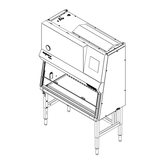
- Page 1 Document: 333D012G 5-18-2007 AKER OMPANY OPERATOR’S MANUAL ® III Advanceº SterilGARD Class II, Type A2 Biosafety Cabinet MODEL SG403A / SG603A This manual includes information for installation, operation, maintenance and spare parts. We recommend that it be kept near the cabinet for ready reference.
- Page 2 INTRODUCTION AND WELCOME It is a pleasure to welcome you to the growing number of customers who own and operate Baker cabinets and glove boxes. As the inventors of the laminar flow biological safety cabinet and the leaders in the field, Baker people take special pride in providing a cabinet that is designed for maximum performance.
-
Page 3: Table Of Contents
Document: 333D012G 5-18-2007 TABLE OF CONTENTS ® SterilGARD III Airflow and Base Features........................... 4 Fig.1, Airflow Inside Cabinet ..............................4 Base Features ....................................5 Cabinet Pressure Plenums................................6 Design Details....................................6 Motor / blower capacity................................6 Air balance adjustments................................6 Tested HEPA filters.................................. - Page 4 Document: 333D012G 5-18-2007 Filter Leak & Smoke Testing................................ 24 Filter leak test procedure – Down flow filter..........................24 Filter leak test procedure – Exhaust filter ..........................25 Airflow smoke pattern test................................ 25 Maintenance Notes ..................................25 Cleaning the Work Area ................................25 Ultraviolet Germicidal Lamp (Optional) ..........................
-
Page 5: Sterilgard ® Iii Airflow And Base Features
Document: 333D012G 5-18-2007 ® I – FUNCTION OF THE SterilGARD III Advanceº ® SterilGARD III Airflow and Base Features Room air enters the front access opening of the cabinet at a minimum of 100 FPM [0.508m/sec] then enters the front work surface perforation. Most of the HEPA filtered down flow air passes through a diffuser but some of the air is dumped down the back of the viewscreen creating a high velocity air curtain at the front access opening. -
Page 6: Base Features
Document: 333D012G 5-18-2007 Base Features • Meets NSF 49 standard for Class II, Type A2 biosafety cabinet. • HEPA filtration of air before it enters the work area. • Front accessibility to electrical components, lamp, blower, and filters. • Sliding viewscreen sloped 10 degrees for worker comfort. •... -
Page 7: Cabinet Pressure Plenums
Document: 333D012G 5-18-2007 Cabinet Pressure Plenums The cabinets work area is surrounded by negative pressure and all external seals are under negative pressure. All internal positive pressure plenum seals are surrounded by negative pressure plenums. Design Details Motor / blower capacity A motor / blower’s capacity is measured by its ability to provide a nearly constant volume of air as resistance increases because of filter loading. -
Page 8: Towel Guard
Document: 333D012G 5-18-2007 Towel guard The towel guards are located under the work surface at the bottom rear and sides of the return-air plenums. Acting as a protective screen, integral to the interior walls, they help prevent wipes and other paper materials from being drawn into the blower system. -
Page 9: Motor / Blower Assembly
Document: 333D012G 5-18-2007 Motor / Blower assembly The motor and blower are assembled on a slide plate. This allows the assembly to be easily removed from the positive pressure plenum for faster servicing or replacement. Cable ports (Optional) A cable port is located in the cabinet’s left and right side walls. It provides a way of introducing power and data cables, or siphoning tubes into the work area of the cabinet without having to go through the front viewscreen access opening. -
Page 10: Specifications
The cabinet may be provided with an optional lift that requires 115V AC at 2 Amps intermittent duty. The lift duty cycle is 1 minute on, 9 minutes off. ® The cabinet incorporates the Baker StediVOLT blower motor speed control. This compensates for normal variations in incoming line voltage. -
Page 11: Environmental Conditions
Document: 333D012G 5-18-2007 Environmental Conditions The cabinet is designed for use in the following conditions: • Indoor use • Altitudes up to 2000 meters • Temperature range from 5° C to 40° C • Maximum relative humidity 80% for temperatures up to 31°C decreasing linearly to 50% at 40°C •... -
Page 12: Preparing The Sterilgard ® Iii Advanceº For Use
A claim for restitution should be filed within 15 days. Due to the risk of mishandling by trucking companies, Baker has removed certain parts of the cabinet and has packed them separately. These items are listed on the packing slip, which accompanies the cabinet. Please check the packing slip carefully to be sure that all items have been located. -
Page 13: Exhausting Into The Room
Document: 333D012G 5-18-2007 small cardboard box. 6. Install the drain valve to the threaded pipe nipple. The nipple is located on the left underside of the cabinet drain pan. 7. Be sure to remove the protective material covering the cabinet exhaust opening. 8. - Page 14 Document: 333D012G 5-18-2007 Cabinet Sash Exhaust Flow Range *Suction Min/Max (Inches W.C.) Model Height (Approximate) (Inches) (CFM) SG403A 8” [203.2mm] 322 / 520 [152 / 245 L/sec] 0.05 / 0.25 [12.4 / 62.3 Pa] 10” [254mm] 401 / 585 [189 / 276 L/sec] 0.08 / 0.30 [19.9 / 74.7 Pa] SG603A 8”...
-
Page 15: Final Connections And Tests
For additional start up and use procedures, reference Section III, Proper Cabinet Use FOR MORE INFORMATION For a complete listing of articles, papers, and reports related to containment, clean air products and safety, contact The Baker Company for our complete Bibliography or visit our website at www.bakerco.com - 14 -... -
Page 16: Iii - Proper Cabinet Use
In order to keep the interior work area clean and free of particulates, all Baker biosafety cabinets are designed for continuous operation. If the blower is turned off, the work area will become contaminated with room air. Therefore it is recommended that the blower be left on at all times. -
Page 17: Programmable Delay Off Time Function
Document: 333D012G 5-18-2007 • Ultraviolet (UV) Light On / Off [Optional] – A bulb, which produces light in the ultraviolet range, may be used to help disinfect the work area. This switch controls the UV Light inside the work area if the UV Light option is installed. -
Page 18: Start-Up Procedure
Document: 333D012G 5-18-2007 1 hour increment programming: 1. Press and hold the pushbutton of the device you want to program. 2. In about 3 seconds you will hear a short ‘beep’. Continue to hold the pushbutton. In about an additional 3 seconds you will hear a longer ‘beep’. This indicates that you have turned the device ON, are in the programming mode for the device, and have programmed it to turn OFF in 1 hour. -
Page 19: Reacting To Spills
Document: 333D012G 5-18-2007 movements. Since all of the equipment you need is already in the cabinet, it will not be necessary to move your arms in and out through the air barrier. 3. Because opening and closing doors in the laboratory causes air disturbance which might interfere with cabinet airflow, this kind of activity should be kept to a minimum while the cabinet is in use. -
Page 20: Ultraviolet Germicidal Lamp (Optional)
Document: 333D012G 5-18-2007 Ultraviolet Germicidal Lamp (Optional) Ultraviolet lamps lose their effectiveness over time and should be replaced when intensity drops below 40 microwatts per cm at the work surface. Check regularly. WARNING • UV light is hazardous, Do not defeat interlock! •... -
Page 21: Decontamination Procedure
Document: 333D012G 5-18-2007 Decontamination procedure WARNING Only qualified technicians should perform this procedure. 1. Surface-disinfect the inside of the window and all other surfaces on the view screen assembly. 2. Multiply the total volume of the cabinet (49, or 78 ft ) by .3 gram/ft of space to determine the amount of paraformaldehyde required to decontaminate the cabinet. -
Page 22: Cleaning And Disinfecting Stainless Steel
Document: 333D012G 5-18-2007 Cleaning and Disinfecting Stainless Steel Simple Cleaning IMPORTANT Do not use steel wool or steel pads when cleaning stainless steel. Dirt deposits on stainless steel (dust, dirt and finger marks) can easily be removed. Frequently, warm water, with or without detergent, is sufficient. -
Page 23: About The Hepa Filters
Proven efficiency in all HEPA filters used in Baker cabinets are 99.99% for particles 0.3 microns in diameter. The 0.3 micron particle is used as the basis for filter definition because theoretical studies have shown that filtration efficiency should be at a minimum for particles of this diameter, with efficiency increasing for particles either larger or smaller. -
Page 24: Iv - Onsite Checks And Maintenance Procedures
As reported earlier in this manual, each individual cabinet made by The Baker Company is carefully tested before it leaves the factory. Your copy of the test report, which you will find at the back of this manual, gives the factory test ®... -
Page 25: Filter Leak & Smoke Testing
Document: 333D012G 5-18-2007 Condition Adjustment Speed Balancing Down flow Inflow control Damper High High Decrease Increase High Close more High Open more High Decrease Close more Increase Open more High Decrease Open more Increase Close more Chart# 1: Type A2 Air Balancing Guidelines As the HEPA filters load up with particulates, airflow air will be maintained automatically, at least until the down flow filter resistance increases 60%. -
Page 26: Filter Leak Test Procedure - Exhaust Filter
Document: 333D012G 5-18-2007 Filter leak test procedure – Exhaust filter 1. Turn on cabinet blower. 2. If the cabinet has a CEC or HEC, remove the access panel for leak scanning the exhaust filter. If the cabinet is exhausting to the room, remove the exhaust filter protector. 3. -
Page 27: Replacing The Hepa Filters
Document: 333D012G 5-18-2007 Replacing the HEPA Filters When the certifier can no longer set the cabinet air flows to within ±5% FPM of the nominal set point by adjusting the speed control and/or balancing damper then it may mean the filters are loaded with particles and must be replaced. -
Page 28: Accessing The Down Flow And Exhaust Filters
Document: 333D012G 5-18-2007 Accessing the down flow and exhaust filters WARNING Only qualified technicians should perform this procedure. Decontaminate the cabinet before changing the filters. 1. Decontaminate the cabinet and disconnect power. 2. Close the viewscreen. 3. Pull the bottom edge of the vertical dress panel out away from the cabinet. Hinge the dress panel standoff down and lower the vertical panel on it. -
Page 29: Changing The Down Flow Filter
Document: 333D012G 5-18-2007 Changing the down flow filter 1. Loosen the two (2) ½” hex head down flow plenum clamping bolts located on either side of the down flow plenum, alternating two or three revolutions at a time until the plenum is raised about ¼” [6.4mm]. This will allow the down flow filter to slide out the front towards you. - Page 30 Document: 333D012G 5-18-2007 3. Slide the new exhaust filter in all the way in until it stops against the rear filter stop. Be careful not to contact the filter media with your fingers. Align the filter frame, left to right, so it is positioned directly over the exhaust plenum.
-
Page 31: Troubleshooting
Document: 333D012G 5-18-2007 Troubleshooting Here are some suggestions based on our experience with the use and misuse of biological safety cabinets. When a smoke test indicates that there is air flowing from the interior of your cabinet into the surrounding room- 1. - Page 32 Document: 333D012G 5-18-2007 If the Ultraviolet (UV) Light doesn’t work- 1. Make sure the window is completely closed. 2. The Yellow indicator below the switch should be On and the Fluorescent Light should turn Off automatically. 3. Check for proper installation of the bulb in the lamp sockets. 4.
- Page 33 Document: 333D012G 5-18-2007 A lower reading than what was originally recorded on the cabinets test report could be an indication of the following: 1. Blocked or partially obstructed filters. 2. Work surface has been removed. 3. Incorrect airflow balancing. - 32 -...
-
Page 34: Disassembly Instructions
Document: 333D012G 5-18-2007 V – DISASSEMBLY INSTRUCTIONS IMPORTANT Only qualified technicians should perform this procedure. If the cabinet has been in use it will need to be decontaminated. Tools Required: 3/8” Spin wrench | 1/4” Spin wrench | 3/4” Wrench | Cordless drill with 3/8” Socket 1. -
Page 35: Appendix
Document: 333D012G 5-18-2007 Appendix - 34 -... -
Page 36: Replacement Parts List
Document: 333D012G 5-18-2007 Replacement Parts List: Baker Part Number Electrical Items SG403A SG603A Fluorescent lamp 17927 17927 Ultraviolet lamp 18024 18025 Fluorescent lamp holders 34465 34465 Ultraviolet lamp holders – plunger end / fixed end 20281 / 20283 20281 / 20283... - Page 37 Document: 333D012G 5-18-2007 Baker Part Number Mechanical Items SG403A SG603A Down flow HEPA filter 40141 40142 Exhaust HEPA filter 40661 40662 Blower 11429 11418 Armrest pad 40481 40482 Work surface 333X104 336X106 Work surface support 333P706 333P706 Down flow diffuser...
-
Page 38: Dimensional Drawing - Standard Configuration [Sg403A]
Document: 333D012G 5-18-2007 Dimensional Drawing – Standard Configuration [SG403A] - 37 -... -
Page 39: Dimensional Drawing - Standard Configuration [Sg603A]
Document: 333D012G 5-18-2007 Dimensional Drawing – Standard Configuration [SG603A] - 38 -... -
Page 40: Cable Port Illustration
Document: 333D012G 5-18-2007 Cable Port Illustration CABLE PORT GASKET PART# 41126 CABLE PORT RING PART# 190P728 (4) #8-32 X 5/16" WELD STUD WITH HEX CAP NUT/ LOCK WASHER / FLAT WASHER INTERIOR WALL PART#'S 10758 / 10553 / 11307 / 11279 CABLE PORT GASKET PART# 41126 REMOVABLE CABLE HOOK... - Page 41 Document: 333D012G 5-18-2007 Interior View Exterior View [Cable port plug not shown] - 40 -...
-
Page 42: Ladder Schematic: Sg403A
Document: 333D012G 5-18-2007 Ladder Schematic: SG403A - 41 -... -
Page 43: Ladder Schematic: Sg603A
Document: 333D012G 5-18-2007 Ladder Schematic: SG603A - 42 -... -
Page 44: Stand Assembly Leg Extension Procedure
Document: 333D012G 5-18-2007 Stand Assembly Leg Extension Procedure The unit is shipped with the legs bolted in the shipping position. The unit has two work surface height settings per option: 30 1/8” [765mm] and 38 5/8” [981mm] - Adjustable Leg Leveler Option 30”... - Page 45 Document: 333D012G 5-18-2007 Getting the unit off the pallet 1) To protect the floor finish, use a moving blanket. Carefully slide the unit off the pallet onto the moving blanket 2) Slide the unit into its destination room before going further with the assembly/installation. Installing the Adjustable Leg Leveler or Caster Option 3) Lift one end of the unit / stand assembly up a minimum of 7”...
- Page 46 Document: 333D012G 5-18-2007 Only the Adjustable Leg Leveler is shown for clarity 5) If your unit was purchased with the Caster Option be sure to chock the previously installed casters (to prevent cabinet movement) then repeat steps 3 and 4 for the other end of the unit. Raising the Unit to 30 1/8”...
- Page 47 Document: 333D012G 5-18-2007 9) Bolt the leg in position with items 2, 3, and 4. (Two bolts per leg) 10) Repeat steps 7 through 9 for the other leg then remove the blocking. 11) Repeat steps 6 through 10 for the other end of the unit. 12) Plug open holes using item 5.
-
Page 48: Channel Stand Installation Or Removal Procedure
Document: 333D012G 5-18-2007 Channel Stand Installation or Removal Procedure To install a stand, follow steps (1-7). To remove a stand, reverse steps (1-7) 1) First gather all stand components and attaching hardware. The stand parts consist of two sides and one back support. -
Page 49: Replacing Fluorescent And Ultraviolet Lamps
Document: 333D012G 5-18-2007 Replacing Fluorescent and Ultraviolet Lamps Fluorescent Lamp Replacement 1) Turn the fluorescent lamps off by depressing the light on/off switch locating on the right side of the light canopy. 2) Pull the vertical panel out enough at the bottom so that the thumbscrews can be accessed. - Page 50 Document: 333D012G 5-18-2007 Fig. 3 4) Remove FLUOR-A-LOCK tabs (2) from the lamp sockets located on the left side of the fluorescent lamps. (Fig. 3) Using both hands, grasp the lamp carefully near each end and rotate it approx ¼ turn until the lamp is no longer seated in the lamp sockets.
- Page 51 Document: 333D012G 5-18-2007 IMPORTANT Before replacing a UV germicidal lamp it might be necessary to check with an industrial hygienist, safety officer or other qualified person in the lab to make sure that there is nothing stored in the cabinet that could potentially be a hazard to you or could be contaminated by room air.
-
Page 52: Installation Of Exhaust Transition Systems For Sterilgard
Document: 333D012G 5-18-2007 ® Installation of Exhaust Transition Systems for SterilGARD III Cabinets Tools required: 5/16 - Hex wrench and nut driver 11/32 - Hex wrench and nut driver 3/8 - Hex wrench and nut driver 7/16 - Hex wrench and nut driver 11/32 - Combination wrench Unpacking the Transition: 1) Remove contents from the shipping packaging and examine for damage. - Page 53 Document: 333D012G 5-18-2007 Item # Description SG403A SG603A Exhaust transition Exhaust filter access cover (open face) ¼”-20 x ¾” Washer head bolt ¼” Seal washer ¼”-20 x 1” Hex head bolt ¼” Flat washer ¼” Lock washer ¼” 20 Double ended transition mounting bolt ¼”-20 Hex nut Exhaust transition mounting clip Air tight damper assembly (ATD)
-
Page 54: Exhausting Requirements For Hec And Cec
Document: 333D012G 5-18-2007 EXHAUSTING REQUIREMENTS FOR HEC AND CEC Added Height to Type A Exhaust Sash *Exhaust Pressure Cabinet with ET Cabinet Transition Duct Height Flow Rate Loss Model Model Diameter (Inches) (cfm) (” w.c.) ATD / SHORT COLLAR (Inchs) (Inchs) 0.06 11-1/2 / 5-5/16... -
Page 55: Installation Instructions For Hec
Document: 333D012G 5-18-2007 Pressure *Exhaust Pressure Additional Exhaust Sash Loss with **Intake Cabinet Transition Flow Rate Loss Heights Duct Dia. Height BSC Sealed Velocity Model Model Min/Max Min/Max (Inchs) (Inchs) (Inchs) for Decon. (fpm) (cfm) (” w.c.) (” w.c.) 3.80” Decon Box 322 / 520 0.05 / 0.25... -
Page 56: Installation Instructions For Cec
Document: 333D012G 5-18-2007 4) Place the exhaust transition over the exhaust filter opening. Align the two holes at each end of the transition with the ¼” female fasteners that are located at each side of the exhaust filter opening. 5) Install the transition mounting hardware [Items 5, 6&7 (Detail C)] along with transition mounting clip and hardware on the double ended mounting bolt. - Page 57 Document: 333D012G 5-18-2007 lock washer, and (1) one #8-32 nut provided, onto each weld stud and tighten accordingly. Re- install side covers onto seal box and tighten. Mount optional short collar [Item 12] and gasket to the eight (8) studs located at the top of the transition using #8 hardware. [Items 13, 14 & 15 (Detail B)] With the CEC installed and connected to the building exhaust system the cabinet should be certified by a qualified technician to assure proper cabinet performance.
- Page 58 Document: 333D012G 5-18-2007 ATD Assembly (Optional) (Item 11) Gasket (Item 18) Short Exhaust Collar (Optional) Exhaust Filter (Item 12) Access Cover (Items 2 & 17) Exhaust Filter Exhaust Transition (Items 1 & 16) Double-ended transition mounting bolt and seal washer (Items 4 &...
- Page 59 Document: 333D012G 5-18-2007 ATD Assembly (Optional) (Item 11) Short Collar (Optional) (Item 12) Exhaust Filter Access Cover (Items 2 & 17) Gasket (Item 18) Decon Seal Box (Optional) Exhaust Transition (Items 1 & 16) External Damper Control Double-ended transition mounting bolt and seal washer (Items 4 &...
-
Page 60: Airflow Monitor (Afm) Installation And Calibration: Sterilgard
Document: 333D012G 5-18-2007 ® Airflow Monitor (AFM) Installation and Calibration: SterilGARD III Exhausting to Room, HEC or CEC Exhaust to Room 1) Remove all items from shipping container and identify the following: Contents should include Airgate with 1” [25.4mm] probe installed, Airflow Monitor (AFM) and Velcro Strip (If AFM was not factory installed). -
Page 61: Hec And Cec Exhaust
Document: 333D012G 5-18-2007 HEC and CEC Exhaust 1) Remove all items from shipping container and identify the following: Contents should include Airgate, Airflow Monitor (AFM) with 1” [25.4mm] probe, #8-32 locknut, Cardboard protector sheet, and Velcro Strip. (See Figure 2) 2) Insert the 1”... - Page 62 Document: 333D012G 5-18-2007 Sash Opening Intake airflow at 80 fpm [0.406 m/sec] Model (Inches) (cfm) 8 [203.2mm] SG403A 205 [96.8 L/sec] SG603A 311 [147 L/sec] 10 [254mm] SG403A 256 [121 L/sec] SG603A 389 [184 L/sec] 12 [304.8mm] SG403A 306 [144 L/sec] SG603A 467 [220 L/sec] Cabinet intake airflow values at 80 fpm [0.406 m/sec]...
- Page 63 Document: 333D012G 5-18-2007 #8-32 Cardboard AFM w/Probe AirGate Velcro Locknut Protector Strip Figure 2: Parts Included SLOT FOR PROBE WIRING #8-32 LOCKNUT EXHAUST TRANSITION AIRGATE DETAIL B REMOVE ACCESS PANEL - 62 -...
-
Page 64: Notice - O.s.h.a. Federal Regulation
Document: 333D012G 5-18-2007 Figure 3: Airgate Installation (HEC or CEC) NOTICE – O.S.H.A. Federal Regulation The following in an excerpt form the O.S.H.A. Federal Register Page 22240 and Figure J-9. *Biological hazard signs. The biological hazard warning shall be used to signify the actual or potential presence of a biohazard and to identify equipment, containers, rooms, materials, experimental animals or combinations thereof, which contains, or are contaminated with, viable hazardous agents. -
Page 65: Warranty
The exclusive remedy for any breach or violation of this warranty is as follows: The Baker Company, Inc. will F.O.B. Sanford, Maine furnish without charge repairs to or replacement parts or equipment which proved defective in material or workmanship.
Need help?
Do you have a question about the SterilGARD III Advance and is the answer not in the manual?
Questions and answers
Hello, We have a SterilGARD III Biosafety Cabinet, Model SG603A (Serial 90225). We do not currently have UV light sterilization capability (The UV light button is present on the cabinet, but is not active). This is listed as an option in the manual. Is it possible to install UV bulbs/activate this system for our cabinet?
Yes, the Baker SterilGARD III Advance Biosafety Cabinet, Model SG603A, can be provided with an optional UV lamp. The UV lamp is interlocked with the fluorescent lamp to prevent simultaneous operation. The installation and activation process includes carefully replacing the UV lamp if needed, ensuring it is securely in place, and momentarily turning it on to verify functionality.
This answer is automatically generated