Table of Contents
Advertisement
Quick Links
Advertisement
Table of Contents

Related Manuals for Daikin Clima-Flex CLIC STAND ALONE Series


Summary of Contents for Daikin Clima-Flex CLIC STAND ALONE Series
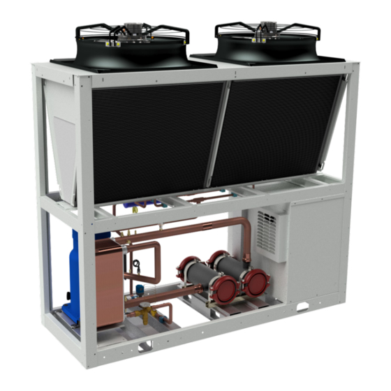
- Page 1 Installation, Operation and Maintenance Manual Group: Chiller Part Number: IOM CLIC STAND ALONE Date: 12 July 2023 CLIC STAND ALONE Series Air-Cooled Scroll Compressor Chiller Water Generator Unit Model 25 TR Refrigerant HFC-410A 50/60 Hz...
-
Page 2: Table Of Contents
Table of Contents Safety Warning.............4 General Description.............5 Features / Benefits............6 Installation and Application Information....8 Refrigeration Schematics.........14 Dimensions and Weights - Packaged Units..15 Refrigerant Charge / Pressure Drop....16 Electrical Data............17 Unit Controller Operation........23 Sequence Of Operation ..........24 Unit Functions..............25 Circuit Functions............26 Alarms ..............28 Controller Use............29 Mapping Table .............32... - Page 3 Pre-Start Checklist - Scroll Compressor Chillers Must be completed, signed, and provided to Clima Flex at least 2 weeks prior to requested start date. Job Name Installation Location Customer Order Number Model Number(s) G.O. Number(s) Chilled Water and Condenser Water for Water-cooled Chiller Initials Piping Complete Water strainer(s) installed in piping per manual requirements...
-
Page 4: Safety Warning
Safety Warning This manual contains safety instructions that must be followed during installation and maintenance of the unit. Read this manual before installing or operating this unit. NOTE: Installation and maintenance should be performed only by qualified personnel who are familiar with local codes and regulations and who have experience with this type of equipment. -
Page 5: General Description
General Description Clima Flex ’s CLIC STAND ALONE Series air-cooled chilled The electrical control center includes all operating controls and water generators are self-contained, complete, automatic chillers equipment protection necessary for reliable automatic operation. designed for outdoor installation. The package units are fully Components housed in a weatherproof control panel. -
Page 6: Features / Benefits
Features / Benefits EFFICIENCY DESIGN Our units are designed to meet the needs of any project. Research conducted by the Engineering Department has resulted Our intelligent process controllers and smart temperature sensors in units with high design efficiency and optimum performance. The selection of the main components, our quality and control provide maximum performance and energy savings. - Page 7 Features and Benefits TESTING Ideal applications for Insitu® spray-applied coatings. Each unit is pressure and vacuum tested and then charged with the refrigerant required for proper operation based on the • Mini-splits customer’s installation conditions. • Packaged enclosures • Condensing units The units are evaluated at full load operation with water flow, heat •...
-
Page 8: Installation And Application Information
Installation and Application Information OPERATING AND STANDBY LIMITS Table 1. Table unit CLIC Maximum standby ambient temperature 130°F (54°C) Maximum operating ambient temperature 105°F (41°C) Minimum operating ambient temperature (standard control) 32°F(0°) Outgoing chilled water temperature 40°F to 65°F (4°C to 18°C) Outgoing chilled fluid temperatures (with antifreeze) - Note that in cases of high ambient tempera- ture, the lowest outgoing water temperature settings may be outside the chiller’s operating enve- 15°F to 65°F (-9°C to... - Page 9 Installation and Application Information The use of spring isolators is recommended for roof applications. Figure 2. Building or wall on one side of the unit. For ground level applications, install the unit on a solid base that will not settle. Use a one-piece concrete slab with a foundation extended below the frost line.
- Page 10 Installation and Application Information Figure 3. Pit installation. COLD WATER PIPES CAUTION To prevent damage to the evaporator and possible failure of the chiller, a supply filter is required in the inlet water piping that con- nects to this evaporator. This filter must be installed prior to operation of the chilled liquid pumps. Field-installed water piping for the chiller should include: A cleanable filter installed at the water inlet to the evaporator to remove debris and impurities before they reach the evaporator.
- Page 11 Installation and Application Information Figure 4. Typical piping of a welded plate evaporator. Thermometer ↑ Flow Thermowell ↑ ↑ Switch Drain Outlet Isolation Vibration Valves Inlet Eliminators Thermometer ↑ Clima-Flex Header's Strainer Vent ↑ Thermowell It is recommended that the field-installed water piping for the chiller include: •...
- Page 12 Installation and Application Information Ten percent of 200 gpm equals a change of 20 gpm per minute, Use one of the following recommendations for additional freeze or a minimum of three minutes to go from the maximum flow to protection: the desired flow.
- Page 13 Installation and Application Information and wiring of the water flow switch are provided in the unit control CONDENSER COIL OPTIONS AND COATING center. Considerations Wire from the Y and R terminals on the switch to the terminals on the unit control panel shown in the field wiring diagrams, page 19 through page 22.
-
Page 14: Refrigeration Schematics
Refrigeration Schematics Figure 5. Refrigerant schematics. iom-clicsa-cf-eng www.clima-flex.com... -
Page 15: Dimensions And Weights - Packaged Units
Dimensions and Weights - Packaged Units Figure 6. Dimensional configuration. www.clima-flex.com iom-clicsa-cf-eng... -
Page 16: Refrigerant Charge / Pressure Drop
Refrigerant Charge / Pressure Drop Table 3. Refrigerant charge and pressure drop in clic stand alone unit. REFRIGERANT CHARGE EVAPORATOR PRESSURE DROP FAMILY R410A (LBS) R410A (KG) φ PIPE SIZE DP (ft WG) CLIC 1 X 21 1 X 9.5 34.01 Figure 7. -
Page 17: Electrical Data
Electrical Data ELECTRICAL CONNECTION CLIC STAND ALONE units can be ordered with standard multi-point power connections or with optional single-point connections and various disconnect and circuit breaker options. Wiring inside the unit is sized in accordance with the NEC®. The required field wiring varies depending on the configuration of the unit. Refer to page 19-22 for wiring diagram information. Voltage limitations are: 1. - Page 18 Electrical Data Transfer back to the grid Proper transfer of power from the standby generator to the grid is essential to prevent damage to the chiller and must be used to ensure proper operation of the unit. WARNING Stop the chiller before transferring power from the generator to the mains. Transferring power while the chiller is running can cause serious damage to the chiller.
- Page 19 Electrical Data Figure 8. Typical field wiring diagram of the 220V unit (single point connection with all options shown) TRANSFORMER 1 PHASE DETECTOR TIMER COMPRESSOR MC1-AUX www.clima-flex.com iom-clicsa-cf-eng...
- Page 20 Electrical Data iom-clicsa-cf-eng www.clima-flex.com...
- Page 21 Electrical Data Figure 9. Typical field wiring diagram of the 440V unit (single point connection with all options shown) TRANSFORMER 1 PHASE DETECTOR TIMER COMPRESSOR MC1-AUX www.clima-flex.com iom-clicsa-cf-eng...
- Page 22 Electrical Data iom-clicsa-cf-eng www.clima-flex.com...
-
Page 23: Unit Controller Operation
Unit Controller Operation GENERAL DESCRIPTION BASIC OPERATING PARAMETERS MICROCHILLER MICROCHILLER The following parameters are intended for fast equipment startup and unit configuration. μChiller is Carel’s solution for the complete management of chillers and air/water and water/water heat pumps. The maximum configuration manages 2 compressors per circuit (On/Off or Parameter Value... -
Page 24: Sequence Of Operation
Sequence Of Operation Figure 10. Sequence of operation of the unit. UNIT ENERGIZED Is the emergency stop active? Is the main control active? Is the motor saver active? Is microchiller Microchiller On Is a high Is a low Are there alarms for Are there pressure pressure... -
Page 25: Unit Functions
Unit Functions CIRCUIT LOGIC CONTROL The calculations in this section are used in unit-level control logic or all-circuit control logic. Circuit enablement EVAPORATOR DELTA T • A circuit must be enabled to start if the following conditions The Delta T of the evaporator water is calculated as the are met: temperature of the water entering minus that leaving through all •... -
Page 26: Circuit Functions
Circuit Functions CIRCUIT STATES T6 - Pre-open to Off The circuit will always be in one of four states: Any of the following is required: Off - The circuit is not running. • Unit status = Off Pre-open - The circuit is preparing to start up Running - The •... - Page 27 Circuit Functions OVERHEATING CONTROL STATUS OPERATION TXV Operation The measurement of refrigerant flow to the evaporator is the exclusive function of a TXV. It must measure this flow at precisely the same rate at which the refrigerant is evaporated by the heat charge. The TXV does this by maintaining the coil with enough refrigerant to maintain the correct superheat of the suction gas leaving the evaporator coil.
-
Page 28: Alarms
Alarms MICROCHILLER CONTROL Alarm Description This alarm indicates when the water return sensor is damaged or broken. This alarm indicates when the water injection sensor is damaged or broken. This alarm indicates when there is a problem with or water flow problem. This alarm usually appears together with the A10 alarm as it depends on the configuration to which the pump was com- missioned, otherwise the current equipment containing this controller simply has a pump configured in this case this alarm goes together with the current pump configuration. -
Page 29: Controller Use
Controller Use DESCRIPTION OF MICROCHILLER When this icon is present on the controller it means FORNTAL DISPLAY BUTTONS (Stand alone) that the freeze protection process has started, however this symbol is also present when switching from cold to hot. Button up When this button is pressed, you can scroll to the When this icon is present on the controller it means previous parameter and in programming mode it is... - Page 30 Controller Use • This parameter is the current setpoint in COOL mode but read only. • Press the down key again and the UON menu will appear, from here you can change the units of measurement. • Press the down arrow key and the SEtC parameter will appear.
- Page 31 Controller Use DESCRIPTION OF THE INTERFACE SCREEN OF THE CAREL APPLICATION VIA CELLULAR PHONE The following image shows the interface of the carel application through Bluetooth communication and monitoring of equipment operation. NOTE: The microchiller controller cannot be used in tandem units. www.clima-flex.com iom-clicsa-cf-eng...
-
Page 32: Mapping Table
Mapping Table Coil Status Data Init Index Size Acronym UoM Description Type Value Value Value U001 BOOL R/W FALSE U001 - User pump 1 reset hour counters U004 BOOL R/W FALSE U004 - User pump 2 reset hour counters U010 BOOL R/W FALSE U010 - Enable set point compensation (0=Disabled, 1=Enabled) - Page 33 Mapping Table Data Init Index Size Acronym UoM Description Type Value Value Value DevRotReq_ BOOL Request comp.2 circ.1 by DeviceRotation Comp2Circ1 ClrH BOOL FALSE ClrH - Delete alarms log (0=No, 1=Yes) UnitOn_Slv BOOL Unit ON/OFF status (0=OFF, 1=ON) sent to Secondary board UsrPmp2_On_Slv BOOL Command to manage user pump 2 (Secondary board)
- Page 34 Mapping Table Init Index Size Acronym DataType Description Value Value Value U028 REAL R/W 0 DELTAKELVIN U028 - Remote set point off set E046 UINT R/W 1 E046 - ExV valve type for EVD EVO (1=CAREL EXV, ...) U031 REAL R/W 10 DELTAKELVIN U031 - High water temp.
- Page 35 Mapping Table Init Index Size Acronym DataType Description Value Value Value C015 UINT(5..999) R/W 30 SECOND C015 - Comp. load up time C016 UINT(5..999) R/W 10 SECOND C016 - Comp. load down time S021 UINT R/W 0 HOUR Time band hours C020 UINT(5..999) R/W 720...
- Page 36 Mapping Table Init Index Size Acronym DataType Description Value Value Value Hc82 USINT(0..2) R/W 1 Hc82 - Analogue output 2 secondary confi g. (0= Not used, 1=Source fan on/off , 2=Source fan mod) AI_CfgLim- USINT R/W 9 AI_CfgLimMax_Grp3 - Lim max probe group 3 Max_Grp3 S056 UINT(20..999)
- Page 37 Mapping Table Init Index Size Acronym DataType Description Value Value Value Hc16 USINT R/W 0 Hc16 - Digital input 1 confi g. on Secondary board (0=Not used, 1=User fl ow switch, 2=Comp.1 circ.2 overload, 3=Comp.2 circ.2 overload, 4=Remote ON/OFF, 5=Cool/Heat, 6=2nd set point, 7=Remote alarm, 8=User pump 1 overload, 9=LP pressure switch, 10=User pump 2 overload, 11=Remote cmd 3, 12=Remote cmd 4, 13=Source alarm)
- Page 38 Mapping Table Init Index Size Acronym DataType Description Value Value Value S070 REAL R/W 0 DELTAKEL- S070 - Cond.1 frost temp. probe off set S071 REAL R/W 0 DELTAKEL- S071 - Cond.2 frost temp. probe off set S069 REAL R/W 0 CELSIUS S069 - Temperature set point for fan-defrost function (0=Function disabled)
- Page 39 Mapping Table Init Index Size Acronym DataType Description Value Value Value Hc43 USINT R/W 0 Hc43 - Analogue input 3 confi g. on Secondary board (0= Not used, 1= Source water delivery temp., 2= Outside temp., 3= Discharge temp., 4= Condensing temp., 5= Suction temp., 6= Evaporation temp., 7=Common delivery temp., 8= Delivery water evap.2 temp.) Hc44...
- Page 40 Mapping Table Init Index Size Acronym DataType Description Value Value Value PwrRunCircs_Perc REAL PERCENT PwrRunCircs_Perc - Circuit capacity percentage by compressors ON AFC2 REAL CELSIUS AFC2 - Cond.2 frost temp AFE1 REAL CELSIUS AFE1 - Evap.1 frost temp. AFC1 REAL CELSIUS AFC1 - Cond.1 frost temp IOprbCfgWrn...
- Page 41 Mapping Table Init Index Size Acronym DataType Description Value Value Value PwrRunCircs_Perc REAL PERCENT PwrRunCircs_Perc - Circuit capacity percentage by compressors ON AFC2 REAL CELSIUS AFC2 - Cond.2 frost temp AFE1 REAL CELSIUS AFE1 - Evap.1 frost temp. AFC1 REAL CELSIUS AFC1 - Cond.1 frost temp IOprbCfgWrn...
- Page 42 Mapping Table Index Size Acronym DataType R/W InitValue UoM Description Value Value BOOL FALSE Circuit 2 - Discharge pressure probe broken or disconnected alarm BOOL FALSE Circuit 2 - Condensing temperature probe broken or discon- nected alarm BOOL FALSE Circuit 2 - Suction pressure probe broken or disconnected alarm BOOL FALSE...
- Page 43 Mapping Table Index Size Acronym DataType R/W InitValue UoM Description Value Value RevVlv_Circ2 BOOL FALSE RevVlv_Circ2 - Reversing valve for refr. circ.2 (0=Cooling, 1=Heating) OilEquVlv_Circ2 BOOL FALSE Oil equalisation solenoid valve circ.2 HeatCool BOOL TRUE HeatCool - Unit in cooling mode (0=Heating, 1=Cooling) DfrRun_Circ1 BOOL FALSE...
-
Page 44: Vdf Compressor Controller
Vdf Compressor Controller CONTROL PANEL INDICATOR LIGHTS The following instructions apply to the graphical LCP (LCP 102): If certain threshold values are exceeded, the alarm LED lights up The control panel is divided into four functional groups: and/or the alarm LED lights up. An alarm status and alarm text are displayed on the control panel. - Page 45 Vdf Compressor Controller Use [Quick Menu] to program the parameters belonging to the The [Reset] key is used to reset the frequency converter after an Quick Menu. It is possible to switch directly between the Quick alarm (trip). It can be selected as [1] Enable or [0] Disable using Menu mode and the Main Menu mode.
- Page 46 Vdf Compressor Controller • 8-37 Maximum Inter-Carriage Delay 8-38 Maximum Inter- After selecting a parameter group, select a parameter with the Carriage Delay navigation keys. The middle section of the display shows the number and name of the parameter as well as the value of the •...
-
Page 47: Startup And Shutdown Procedures
Startup and Shutdown Procedures WARNING The installer must take these procedures into account; his personnel must be qualified and certified to perform the i nstallation in order to comply with all specifications and good practices to ensure proper operation of the unit. PRE-START-UP CHECKLIST The following data should be checked before putting the unit into operation. - Page 48 Startup and Shutdown Procedures Check that the water filter is clean. Check that all service valves are open. Check the correct structure of the water supply. Check that all pipes are filled with water and that air has been evacuated. Check thermometers (not included from factory).
- Page 49 Startup and Shutdown Procedures After completing the inspection of the above installation points and ensuring that all elements of the unit are correct, the unit can be powered up. Turn the switch on the CONTROL UNIT to the ON position to power the control unit with 24 volts. START-UP After powering up the controller, wait 5 minutes for the unit to be ready to operate.
-
Page 50: Unit Maintenance
Unit Maintenance MAINTENANCE • Check that safety devices are operational and properly adjusted. Service or maintenance of these units should be performed by • Make sure that the system is not leaking. experienced personnel with specific refrigeration training. Check • Check the compressor current level. Repeated safety devices and cycle control components should be •... - Page 51 Unit Maintenance Before adjusting the superheat, verify that the unit charge is correct and that the liquid line is completely full and free of bubbles, WARNING and that the circuit is operating under stable load conditions The superheat suction for the evaporator suction discharge is factory Risk of electric shock, may cause injury and death.
- Page 52 Unit Maintenance PHYSICAL INSPECTION Cleaning of the condenser with Plan pressurized water (twice a month) Real Refrigerant pressure check Plan (quarterly) Real Inspection of fan blades, cleaning Plan of fan blades (Quarterly) Real Compressor power consumption Plan check to determine refrigerant loss (quarterly) Real Compressor...
-
Page 53: Troubleshooting Chart
Troubleshooting Chart TROUBLESHOOTING CHART Problem Possible causes Possible corrective actions Main or compressor disconnect switch Circuit breaker closed. open. Fuse damaged, circuit breakers open. Check the electrical circuit and possible short circuit, line to ground, loss of connections or motor windings causing the failure. Replace the fuse and reset the compressor brakes, only after detecting and correcting the cause of the fault. - Page 54 Troubleshooting Chart Problem Possible causes Possible corrective actions Dirty evaporator. Backwashing or chemical cleaning. Lack of refrigerant. Check for leaks, repair and add the necessary charge. Check liquid sight glass. Low water flow. Adjust the water flow required for the equipment. Expansion valve malfunction or failure.
- Page 55 Troubleshooting Chart Problem Possible causes Possible corrective actions Low oil level. Adjust the water flow required for the equipment. Insufficient water flow - level too high. Check or replace (if necessary) the valve and adjust the proper superheat. Solenoid valve return oil not open. Check circuit and possible problem of solenoid valve not opening, if necessary replace.
- Page 56 iom-clicsa-cf-eng www.clima-flex.com...
Need help?
Do you have a question about the Clima-Flex CLIC STAND ALONE Series and is the answer not in the manual?
Questions and answers