Table of Contents
Advertisement
Engineering Data
(Installation, Maintenance Manual)
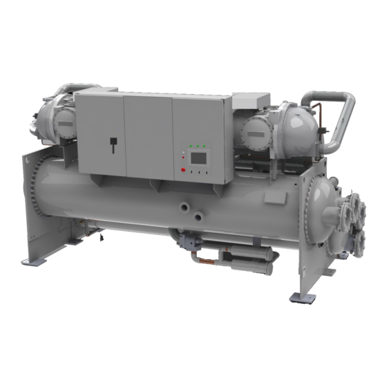
Single Screw Chillers
This manual is applicable to following models and their derived and
modified models.
ZUWCM/DM ZUW.C-B ZUWY ZUWV ZUW-HCA
Thanks for purchasing DAIKIN chiller.
The Manual specifies safety, installation and maintenance precautions.
Please read through the manual before installation and use.
For future reference, please be sure to keep it safe.
Engineered for Flexibility and performance
IMM Chiller universal part
Category: Single Screw Chiller
Date: Mar. 2019
New Part No.: Z8100180-09
Prior Part No.: Z8100180-08
Advertisement
Table of Contents


Need help?
Do you have a question about the ZUWCM/DM and is the answer not in the manual?
Questions and answers