Daikin WDC Installation, Operation And Maintenance Manual
Centrifugal chillers
Hide thumbs
Also See for WDC:
- Installation and maintenance manual (36 pages) ,
- Installation and maintenance manual (12 pages)
Table of Contents

Related Manuals for Daikin WDC


Summary of Contents for Daikin WDC
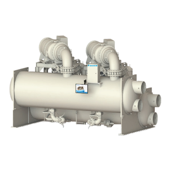
- Page 1 Installation, Operation, IOM 1281-2 and Maintenance Manual Group: Chiller Part Number: IOM1281-2 Date: July 2023 Centrifugal Chillers Model WDC, WCC, A Vintage 600 to 2700 Tons (2100 to 9500 kW) R-134a or R-513A Refrigerant 60/50 Hz...
-
Page 2: Table Of Contents
©2023 Daikin Applied, Minneapolis, MN. All rights reserved throughout the world.This document contains the most current product information as of this printing. Daikin Applied Americas Inc. has the right to change the information, design, and construction of the product represented within the document without prior notice. - Page 3 From starter to chiller unit (remote mounted) Centrifugal chillers with water cooled oil coolers must have a 115 volt normally closed water solenoid valve installed in the oil cooler water supply line. Daikin Applied recommends ASCO Type 8210B27 solenoid valve or approved equal and 40-mesh strainer. Daikin Applied does not supply these components.
-
Page 5: Introduction
Polyolester Oil, commonly known as POE oil is a synthetic oil used in many refrigeration systems, and may be present in this Daikin Applied product. POE oil, if ever in contact with PVC/CPVC, will coat the inside wall of PVC/ CPVC pipe causing environmental stress fractures. -
Page 6: General Description
Most necessary equipment protection and operating The WDC series is equipped with two compressors operating controls are factory installed in the control panel. in parallel on a single evaporator and condenser. The WCC... -
Page 7: Installation
BACK VIEW END VIEW NOTES: DAIKIN APPLIED IS NOT A LICENSED NOR CERTIFIED RIGGING SPECIALIST. IT IS THE CUSTOMER'S RESPONSIBILITY TO CONSULT A CERTIFIED RIGGING CONTRACTOR TO RIG, LIFT, AND MOVE COMPONENTS & SUBCOMPONENTS PROPERLY AND SAFELY. LIFT THE UNIT BY ATTACHING CHAIN HOISTS TO THE ROUND LIFTING HOLES LOCATED ON THE TUBESHEETS. -
Page 8: Location
They must be installed so that they are flush with the edges of the unit feet. Most WDC/WCC units have six mounting feet although only the outer four are required. Six pads are shipped and the installer can place pads under the middle feet if desired. -
Page 9: Operating Limits
40 (4.4) 104 (40) NOTES: Contact a Daikin Applied representative for performance at specific operating conditions, as some limits depend on unit configuration (including heating and heat recovery mode limits) Antifreeze temperature limits must have appropriate glycol concentration Depends on specific selection/rating conditions... -
Page 10: Water Piping
Daikin Applied product. POE oil, if ever in contact with This product, in its standard configuration, is equipped with PVC/ CPVC, will coat the inside wall of PVC/CPVC pipe a shell and tube evaporator with carbon steel shell and causing environmental stress fractures. -
Page 11: Vessel Drains At Startup
Installation Vessel Drains at Startup System Water Volume The unit is drained of water at the factory. Drain plugs for each All chilled water systems need adequate time to recognize a vessel head are shipped separately in the control box. Units load change, respond to that load change and stabilize, without are shipped with the drain plug in the top water box drain hole undesirable short cycling of the compressors or loss of control. -
Page 12: Cooling Tower Control
(tower) cooling to mechanical cooling. refrigerant from migrating to the condenser. Moisture in the Daikin Applied chillers will start with entering condenser water air can condenser on the cooler surfaces of the un-insulated temperature as low as 55°F (42.8° C) providing the chilled condenser barrel if flow is present when the chiller is idle. -
Page 13: Relief Valves
(caused by equipment malfunction, fire, etc.) to the atmosphere. Table 3: WDC, WCC A Vintage Relief Valve Data Evaporator Condenser Oil Sump... -
Page 14: Oil Coolers
Daikin Applied centrifugal chillers have a factory-mounted, city water employed. water-cooled oil cooler, temperature-controlled water regulating valve and solenoid valve per compressor. All WDC units have oil cooler connections located on the right hand tube sheet under the evaporator Figure 9... -
Page 15: Oil Heater
Installation Oil Heater The oil sump is equipped with an immersion heater that is installed in a tube so that it can be removed without disturbing the oil. Figure 9: Oil Cooler Water Connection - Right side Figure 10: Oil Cooler Water Connection - Middle www.DaikinApplied.com IOM 1281-2 •... - Page 16 Installation Figure 11: Oil Cooler Piping Across Chilled Water Pump - Models 079-126 Figure 12: Oil Cooler Piping With City Water - Models 079-126 IOM 1281-2 • CENTRIFUGAL WATER CHILLERS www.DaikinApplied.com...
- Page 17 Installation Figure 13: Typical Refrigerant Flow Diagram - Models 079-126 FLOW CHART LEGEND P102 CHECK VALVE SUCTION LINE LIQUID INJECTION LINE ELECTRONIC EXPANSION VALVE MOTOR COOLING LINE COMPRESSOR TEMPERATURE SENSOR DISCHARGE LINE SIGHT GLASS P202 SHUTOFF VALVE HOT GAS BYPASS LINE (OPTONAL) THREE-WAY VALVE P102 P201...
-
Page 18: Field Wiring
2000V; 90°C or 105°C rated conductors should be used for voltages greater Figure 15: Wiring for Optional Display than 2000V. Refer to the unit nameplate and the Daikin Tools selection report for the correct electrical ratings. DANGER Qualified and licensed electricians must perform wiring. -
Page 19: Building Automation Systems (Bas)
Surge Capacitors – obtained from the Daikin Applied sales office – for generator sizing purposes. The reference data will show the RLA and Surge capacitors are an option for some unit-mounted, low LRA, which is for each compressor. -
Page 20: Field Wiring, Controls & Starters
115 Vac to 220 Vac is 12 gauge for a maximum compressor motor terminals shall be made with copper length of 50 feet. If greater than 50 feet, refer to Daikin wire and copper lugs only. Main power wiring between Applied for recommended wire size minimum. - Page 21 Installation Figure 16: Field Wiring Schematic www.DaikinApplied.com IOM 1281-2 • CENTRIFUGAL WATER CHILLERS...
- Page 22 Installation Figure 17: Compressor Control Box IOM 1281-2 • CENTRIFUGAL WATER CHILLERS www.DaikinApplied.com...
- Page 23 Installation Figure 18: Unit Control Box www.DaikinApplied.com IOM 1281-2 • CENTRIFUGAL WATER CHILLERS...
- Page 24 10. Restart by Daikin Applied service technicians will be 3. If there is concern about the possibilities of damage required and paid to Daikin Applied by the owner or and loss of charge during storage, the customer can contractor. It is prudent to take photos when the unit is...
-
Page 25: Retrofit Knockdown
Chillers are built and shipped completely assembled with bolt-together construction on major components for field disassembly and reassembly on the job site. All componets for WDC/WCC chillers will be doubled for a second compressor on each unit Figure 19: Bolt-Together Construction Option - Representative Schematic... - Page 26 • Site reassembly must be supervised or completed • Unit ships with vessel and/or head insulation, if ordered. by Daikin Applied service personnel. Cost for unit reassembly and supervision by Daikin Applied service • Unit ships with replacement refrigerant gaskets and is not included in the purchase price of the equipment.
- Page 27 Follow 2 holes on the top of the oil pump and then connect the rigging and moving instructions carefully. Daikin Applied is not chain hoists. Eye bolts are not provided. Rolling dollies a licensed nor certified rigging specialist. It is the customer’s may also be used.
- Page 28 Refer to the as-built submittal drawings wraps at all times on valve components. provided by a Daikin Applied sales representative for configuration-specific details. 9. Disconnect power leads from starter. The compressor dimensions vary by model. All dimensions and 10.
- Page 29 Installation Separating Vessel Stacks Unit Reassembly After removing compressor and associated lines for Type The level of disassembly required for unit installation will be A knockdown, the liquid line connecting the evaporator varied. For all steps, use new refrigerant gaskets and o-rings and condenser as well as the oil sump would need to be provided.
- Page 30 Installation Figure 27: Liquid Line Assembly Figure 28: Oil Sump/Oil Cooler Assembly IOM 1281-2 • CENTRIFUGAL WATER CHILLERS www.DaikinApplied.com...
- Page 31 DEPENDING ON COMPRESSOR SIZE. JUNCTION BOX NOT ON ALL UNITS. MOTORS. CONNECT LEAD 155 TO TERMINAL SECOND HEATER CABLE FROM IF 2 BOX IS NOT COMPR. ON WSC / WDC / WCC USED. 079-087 ONLY. HIGH PRESSURE SWITCH VFD / STARTER CONTROL CABLE...
- Page 32 Installation Figure 31: Unit Electrical and Sensor Locations VA.NE SOLE.NO.f.DS VANE VANE l!z: UNLOAD LOAD �� � �c= �� "U L " �w �� � , � , � HP /CO.NJJ. PRESS -!l- cl � � • • � . ="fb,�...
-
Page 33: Operation
Electric shock hazard. Can cause personal injury or equipment and should be completed prior to start-up. The Daikin Applied damage. This equipment must be properly grounded. service technician is responsible for checking the wiring and Connections to and service of the MicroTech control panel making the appropriate control changes. -
Page 34: Ice Mode Operation
During pumps depending on site requirements. the initial startup of the chiller, the Daikin Applied technician will be available to answer any questions and instruct the proper The same Modes setting must be replicated on each chiller in operating procedures. -
Page 35: Human Machine Interface (Hmi)
Operation Human Machine Interface (HMI) Enabling To enable the chiller and its compressors when the “Control The HMI is turned on/off with a switch located at the lower Source” is “Switches” or “BAS,” all rocker switches (three right-hand edge of the display panel. Screen control buttons rocker switches for single compressor units, four rocker are located to either side of it and elicit on-screen prompts switches for dual compressor units) and the Remote Switch, if... - Page 36 Operation Figure 34: Home View Screen The Home View Screen (Figure 34) shows the basic operating Table 10: Compressor Status Possibilities condition of the chiller. Note that the chiller displayed on all Complete STATUS Text screens will be representative of the actual chiller, showing Notes (in priority sequence) either one or two compressors depending on the chiller model.
- Page 37 39. Chiller Model “WCF” is the general software category for The bottom icon bar will be visible on all screens with the WSC, WDC, WCC, and TDC models (see active screen highlighted in white. “Figure 50: Settings View - Modes” on page 47).
- Page 38 Operation Figure 39: Unit Detail View Screen IOM 1281-2 • CENTRIFUGAL WATER CHILLERS www.DaikinApplied.com...
- Page 39 Operation Figure 40: Evaporator Information Figure 41: Compressor Details NOTE: Chiller data will populate in the Power box if the Full Metering capability has been installed and wired. www.DaikinApplied.com IOM 1281-2 • CENTRIFUGAL WATER CHILLERS...
- Page 40 Operation The Compressor State Information on the right side of the speeds be as close as possible and must be within 30 seconds screen is a compilation of the events that the chiller sequences of each other. The valves are factory set so that the vanes will through at startup.
- Page 41 Demand Limit operate the unloading piston for positioning the inlet guide vanes for capacity control. WDC, dual compressor chillers, The maximum amp draw of the compressor(s) can be limited have completely independent lubrication systems for each by a 4 to 20 mA signal on the Demand Limit analog input.
- Page 42 Operation Figure 43: Typical Oil Flow Diagram - Models WDC IOM 1281-2 • CENTRIFUGAL WATER CHILLERS www.DaikinApplied.com...
- Page 43 Operation Figure 44: Condenser Information Figure 45: Expansion Valve Information www.DaikinApplied.com IOM 1281-2 • CENTRIFUGAL WATER CHILLERS...
- Page 44 • T = Technician Level (The password number for 2. MODES, selects various unit parameters such as liquid technician level is only provided to Daikin Applied injection, timers, pump staging, control source, unit technicians.) mode, etc.
- Page 45 NOTE: Setpoints that have a technician level password operator level. The technician level password number is (T) should only be changed by a Daikin Applied only provided to Daikin Applied technicians.) There is a technician. Contact a Daikin Applied service small delay between pressing the keypad and recording representative for more information.
- Page 46 Operation Figure 48: Settings View - Water Table 12: Water Setpoints Description Default Range Comments Reset Type = Return: Sets the maximum LWT reset that can occur. Maximum Reset Delta-T 0.0 °F 0.0 to 20.0 °F Reset Type = 4-20 mA: Sets amount of reset at 20 mA input. Start Reset Delta-T 10 °F 0.0 to 20.0 °F...
- Page 47 Default Range Comments Chiller Model WCF, WMC WCF is the general software model for WDC, WCC and TDC WCC Enable Disabled (other) Enabled (WCC), Disabled (other) T Will always be Disabled for WDC chillers OFF: everything is off. AUTO: evap pump on, comp, cond pump and tower on...
- Page 48 Operation Figure 51: Settings View - Motor Table 14: Motor Setpoints Description Default Range Comments Nominal Capacity 100 tons 0-2000 tons Sets nominal capacity rating of an individual compressor for staging decisions. Compressor Start: Sets minimum delta between oil sump temp and evaporator saturated temp.
- Page 49 Operation Table 15: Tower Setpoint Settings Description Default Range Comments Valve Position (Bypass) 100% Valve Control Slope Gain 0 to 99 Control gain for temperature (or lift) slope Valve Control Error Gain 0 to 99 Control gain for temperature (or lift) error Valve Control Range (Max) 100% 0 to 100%...
-
Page 50: Tower Control Settings
Operation Figure 52: Settings View - Tower will be used with the Staging selected for the tower. A BAS or Tower Control Settings other control may monitor these outputs to understand when or There are five possible tower control strategies: (I) VFD how much the MicroTech®... - Page 51 Operation Figure 54: Strategy (I) VFD STAGE - VFD Speed vs. Temp flow through the tower until the last fan is staged off. 7. Set Valve Deadband - Lift. The default of 1.0 psi is a recommended initial setting. 8. Set the Valve Control Range to the minimum position to which the valve can go.
- Page 52 Operation To set up in HMI, Strategy (IV) NONE: A. The TOWER Setpoint setting for Cooling Tower Control This control strategy is tower fan staging only. This is not a strategy should be NONE. Tower Valve/VFD should be recommended strategy. In this mode the tower fan staging changed to VALVE STAGE.
- Page 53 Operation Figure 59: Strategy (IV) - NONE Figure 62: Strategy (V) VALVE SP / VFD STAGE - Percent vs. Temperature Cooling Tower Fan Staging (Up to 3 fans) Tower Control Panel MicroTech ® Controller Condenser Temperature (°F) % VFD Speed (3 Fan Stages) % VFD Speed (1 Fan Stage) Figure 60: Strategy (IV) NONE - Temp vs.
- Page 54 Operation Figure 64: Settings View - Alarms Table 16: ALARMS Setpoint Settings Description Default Range Comments Sets the value of condenser saturated temperature below which the condenser pump is forced Condenser Freeze Protect 34.0 °F -9.0 to 45.0 °F ON - occurs when unit is off and chiller senses need to provide flow to address a chiller limit alarm - see “Table 20: Warning Alarms”...
- Page 55 Failure to do so will result in incorrectly labeled History files. The version numbers shown are the controllers’ software identification. These numbers may be required by Daikin Applied to answer questions about unit operation or to assist in possible future upgrades of software.
-
Page 56: Alarms
Operation Figure 67: Trend History Screen Trend History Screen 2. Warning (Yellow Text) - This alarm limits compressor loading in response to an out-of-normal condition or The Trend History Screen (Figure 67) is accessed by clicking may only be a notification to indicate that the condition the TREND button at the bottom of any screen. - Page 57 Operation Clearing an Alarm that require external intervention (Communication and Sensor Alarms) will immediately show up as Red Alarms on the HMI There are two different indicators that the chiller will generate and prevent the chiller from running until manually cleared at when conditions arise that are affecting the chiller operations.
- Page 58 (Trend.csv and AlarmHistory.csv, ) must be sent together drive. “Copy Service Trends” is only available with the to Daikin Applied. Any other file formats are NOT accepted. technician level password. “Copy Customer Trends” is available for all password levels.
- Page 59 Operation Table 19: Critical Alarms Screen Text Occurs When Action Taken Troubleshooting Clear Evaporator Press < Low Suction Pressure-Stop SP for Causes: Low or No Evaporator Water Flow. Low Evaporator Pressure 60 sec. Delay reduces linearly to 10 sec at 10 psi below Rapid Stop refrigerant level in evaporator.
- Page 60 Operation No flow indicated for (5 sec) with Condenser Pump Condenser Pump #1 Condenser flow not detected. Causes: improper #1 ON AND [the other pump is available (per the Rapid Stop/No Start Manual Fault pump wiring evaporator Pump SP) AND has not faulted] No flow indicated for (5 sec) with Condenser Pump Condenser Pump #2 Condenser flow not detected.
-
Page 61: Controller Inputs And Outputs
Operation Controller Inputs and Outputs As outlined below, inputs and outputs vary between the unit controller and the compressor controller. Unit Controller Inputs and Outputs The following tables list the unit controller inputs and outputs, both analog and digital, as well as the stepper motor outputs. Table 21: Unit Controller, Analog Inputs Description Wiring... - Page 62 Operation Compressor Controller Inputs and Outputs The following tables list analog inputs and digital outputs for the compressor controller as well as the stepper motor outputs. Table 25: Compressor Controller, Analog Inputs Description Source Signal Sensor Range Oil Sump Pressure 0.5 to 4.5 VDC nominal Oil Feed Pressure to Compressor 0.5 to 4.5 VDC nominal...
-
Page 63: Maintenance
Dyes used for refrigerant leak detection are not tested or recommended for when handling POE lubricant. Failure to do so can result in personal injury. use in Daikin Applied chillers. Use of these products may damage and/or POE must not come into contact with any surface or material that might degrade the performance of the equipment and will void the manufacturer be harmed by POE, including certain polymers (e.g. - Page 64 Extreme changes in subcooling reversed), the compressor must be jogged clockwise and/or superheat over a period of time will indicate losses to check rotation. For assistance, call the local Daikin of refrigerant or possible deterioration or malfunction of the Applied service location.
- Page 65 It is recommended that the service of a reliable water Pumping Down treatment company be used. Daikin Applied assumes no If it becomes necessary to pump the system down, extreme responsibility for the results of untreated or improperly care must be used to avoid damage to the evaporator from treated water.
- Page 66 The triple evacuation method is recommended and is and continues to be a preferred method for Daikin Applied particularly helpful if the vacuum pump is unable to obtain the centrifugal chillers. Daikin Applied service or a number of desired 1 millimeter of vacuum.
- Page 67 Zinc unusual circumstances, for example, it might be desirable to There is no zinc used in the bearings on Daikin Applied chillers. sample the lubricating oil shortly after a unit has been placed The source, if any, may be from additives in some mineral oils.
- Page 68 Technical Response at TechResponse@DaikinApplied.com to review the jobsite details. The thermal dispersion flow switch supplied by Daikin Applied, shown in Figure 1, comes as a 2 part unit consisting of a flow NOTE: DO NOT alter or relocate factory installed flow switch.
- Page 69 Maintenance Wiring Step 2: Once steady state minimum desired operating flow is obtained, perform the ‘Teach’ function on the flow switch. The Refer to wiring diagram in the unit control panel. ‘Teach’ function is initiated by holding down the minus ‘-’ button Either AC or DC is used to power the flow switch.
- Page 70 LEDs light and go out step by step. During this time, the output is closed. The unit is in the Daikin Applied offers a variety of maintenance services through operating mode. the local Daikin Applied service office, its worldwide service organization, and can tailor these services to suit the needs of 4.
- Page 71 Meg. Windings (Note 1) tube fouling, particularly in the condenser, where constant Ampere Balance (within 10% at RLA) flow usually prevails. Daikin Applied’s high efficiency heat Terminal Check - measure infrared temp exchangers have very low design approach temperatures, in Motor Cooling Filter Drier Pressure Drop the order of one to one and one half degrees F.
- Page 73 (collectively “Owner”) that Company, at it’s option, will repair or replace defective parts in the event any product manufactured by Company, including products sold under the brand name Daikin and used in the United States or Canada, proves defective in material or workmanship within twelve (12) months from initial startup or eighteen (18) months from the date shipped by Company, whichever occurs first.
- Page 74 Now that you have made an investment in modern, efficient Daikin Applied equipment, its care should be a high priority. For training information on all Daikin Applied HVAC products, please visit us at www.DaikinApplied.com and click on Training, or call 540-248-9646 and ask for the Training Department.
Need help?
Do you have a question about the WDC and is the answer not in the manual?
Questions and answers