Table of Contents
Advertisement
Quick Links
User's Guide
Bioness Inc.
25103 Rye Canyon Loop
Valencia, CA 91355
USA
Telephone: (800) 211-9136 or (661) 362-4850
Website: StimRouter.com
Rx Only
©2022 Bioventus LLC
Bioventus and the Bioventus logo are registered trademarks of Bioventus LLC.
StimRouter and Bioness are trademarks of Bioness Inc. | StimRouter.com
LBL-000709
Labeling LBL-000709 [A] RELEASED
602-00724-001 Rev. A
08/2022
Advertisement
Table of Contents

Related Manuals for Bioness bioventus StimRouter


Summary of Contents for Bioness bioventus StimRouter
- Page 1 Telephone: (800) 211-9136 or (661) 362-4850 Website: StimRouter.com Rx Only ©2022 Bioventus LLC Bioventus and the Bioventus logo are registered trademarks of Bioventus LLC. StimRouter and Bioness are trademarks of Bioness Inc. | StimRouter.com LBL-000709 Labeling LBL-000709 [A] RELEASED 602-00724-001 Rev. A 08/2022...
- Page 2 For more information regarding these recommended procedures, please contact Customer Service. Bioventus is committed to continuously seeking and implementing the best possible manufacturing procedures and servicing routines. Bioness Inc. 25103 Rye Canyon Loop Valencia, CA 91355 USA Telephone: (800) 211-9136 or (661) 362-4850 Website: StimRouter.com...
-
Page 3: Table Of Contents
List of Symbols Table of Contents Caution Chapter 1: Introduction ..................1 Warning Chapter 2: StimRouter User Kit ............... 3 Class II Equipment (Double Insulated) Chapter 3: Warnings and Cautions ..............5 Type BF Applied Part(s) Indications for Use ......................5 Non-Ionizing Radiation Device Use and Suitability ..................... - Page 4 Sensations Caused by Stimulation ................11 E-EFC Setup ......................30 Gel Electrode Expiration Date .................. 11 Controls ........................32 Gel Electrode Placement and Stimulation ..............11 Activity ........................34 Adverse Effects ......................12 More ........................34 Risks Related to the Implant Procedure ..............12 Turning Stimulation On ....................
-
Page 5: Chapter 1: Introduction
E-EFC Specifications ....................49 Gel Electrode Specifications ..................51 System Characteristics ....................51 Privacy of StimRouter Wireless Communiation ............. 52 Chapter 11: Appendix - EMI Tables ............... 53 Introduction Electromagnetic Emissions ..................53 Guidance and Manufacturer’s Declaration Electromagnetic Emissions ....... 54 The StimRouter Neuromodulation System is intended to be operated by patients to help Guidance and Manufacturer’s Declaration Electromagnetic Immunity ...... -
Page 6: Chapter 2: Stimrouter User Kit
Note: Your StimRouter User Kit contains a Medical Device Identification (ID) Card. Complete your card as soon as possible and carry it with you at all times. Your Medical Device ID Card identifies you as a person with an implanted medical device. You may need this card to bypass security screening devices, which are common at airports, grocery stores, libraries, etc. -
Page 7: Chapter 3: Warnings And Cautions
Warnings and Cautions Be sure to follow your doctor’s guidance. Use your StimRouter system only as instructed in the User’s Guide. Indications for Use The StimRouter Neuromodulation System is indicated for pain management in adults who have severe intractable chronic pain of peripheral nerve origin, as an adjunct to other modes of therapy (e.g., medications). -
Page 8: Essential Performance
Essential Performance components, resulting in loss of therapy. Injury or damage can occur during diathermy treatment whether neurostimulation is turned on or off. All patients are The StimRouter System does not have Essential Performance as there is no performance advised to inform their health-care professionals that they should not be exposed necessary (as defined by IEC 60601) to avoid unacceptable risks, in that all sources of to diathermy. -
Page 9: Driving And Operating Machinery
Driving and Operating Machinery High-Frequency Surgical Equipment Remove the Gel Electrode before medical treatment. If you are connected to the StimRouter Turn off stimulation while driving or operating machinery. system and high-frequency surgical equipment, you may experience a skin burn where the Gel Electrodes adhere. -
Page 10: Precautions
Precautions Keep Out of Reach of Children Keep all StimRouter components out of the reach of children. Post-Operative Care Skin Abnormalities After the implant procedure, check the incision site for infection, possible device rejection or other possible adverse effects. Do not adhere the Gel Electrode to skin that is swollen, infected or inflamed or to skin that is broken. - Page 11 • Apply Gel Electrode only to the areas recommended by your doctor. Avoid • Remove the Gel Electrode. placing the Gel Electrode across the head, directly on the eyes, covering the • Notify your physician. mouth, or on the front of the neck (especially the carotid sinus). •...
- Page 12 Environmental Conditions that Affect Use Storage and Handling Keep all StimRouter components dry and protect them from extreme changes in temperature and humidity. Do not use or store your components where they could come in contact with water, such as by sinks, bathtubs and shower stalls. Do not expose them to weather conditions such as rain or snow.
- Page 13 • Move or adjust the receiving antenna. • Move the equipment farther from the receiver. • Contact the dealer or an experienced radio/television technician for assistance. The antenna for each transmitter must not be near to or operating with any other antenna or transmitter.
- Page 14 Gel Electrode • BLUE – E-EFC Blinking: E-EFC is in pairing mode, ready to make Bluetooth connection with MAPP or CPS Gel Electrode Gel Electrode features: (See Figure 5-4) Figure 5-2: The E-EFC attached to the Gel Electrode. • Two gel pads that adhere the Gel Electrode to the skin. The gel pads also transmit the stimulation signal from the E-EFC to the StimRouter lead.
- Page 15 Gel Electrode Liner System Charger Set Every Gel Electrode is supplied with an electrode liner. See Figure 5-5. The liner is used The system charger set is a plug-in AC/DC adapter that connects to a main power supply and to keep the gel pads on the Gel Electrode from drying out. includes a USB C cable, a charger, and interchangeable blades for U.S.
- Page 16 The StimRouter Plus MAPP communicates wirelessly to the StimRouter E-EFC. The StimRouter Plus MAPP is used to: • Turn Stimulation on and off. • Adjust stimulation intensity Set-Up Instructions • Select a stimulation program Please ensure that the StimRouter Plus MAPP has been downloaded on your mobile device. Charging the E-EFC The StimRouter E-EFC comes with a rechargeable Lithium Polymer battery installed.
- Page 17 Connecting the Gel Electrode and E-EFC To connect the Gel Electrode and E-EFC: 1. Obtain a new Gel Electrode or one with gel pads that can still fully adhere to the skin. 2. Check the “Use by” date on the Gel Electrode box. 3.
- Page 18 • If the gel pads start to peel off at the edges or detach from the Gel Electrode, Charging port Gel Electrode immediately dispose of and get a new Gel Electrode. on E-EFC Gel Pad To adhere the Gel Electrode: 1.
- Page 19 Operating Instructions CAUTION: Use only the components designed and manufactured for the StimRouter system. The use of other components may damage your system and cause injury. This section includes instructions on how to operate your StimRouter system, including instructions for: •...
- Page 20 Using the StimRouter Plus MAPP Click the icon on your mobile device to open the StimRouter Plus MAPP. The StimRouter Plus MAPP has four main screens: E-EFC Setup, Controls, Activity and More. Plus and Minus Buttons E-EFC Setup Users can connect new E-EFCs and modify connected E-EFCs from the E-EFC Setup screen.
-
Page 21: Controls
Controls Users can modify settings of a selected E-EFC, enter and exit stimulation mode, and view program parameters from the Controls screen. • Change the selected therapy program by pressing the left and right arrows. A therapy program will not be active unless started from the MAPP. Plus and Minus Buttons •... -
Page 22: Activity
Turning Stimulation On is reached, press “Save Default”. The saved default stimulation will be noted by a lighter colored intensity bar. Stimulation will begin at the default level whenever To turn stimulation on from the StimRouter Plus MAPP: stimulation is started for the selected program. Stimulation can be turned on from either the StimRouter Plus MAPP or E-EFC. -
Page 23: Turning Stimulation Off
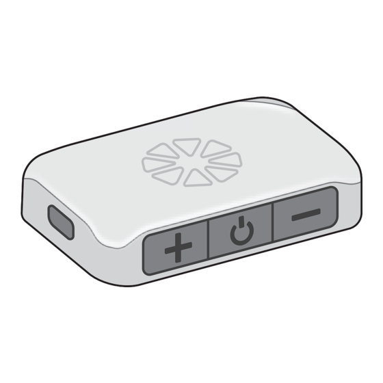
• Do not touch the gel pads on the back of the electrode with both hands while stimulation is turned on. See the “Removing the Gel Electrode” section in this guide. E-EFC Charging Socket Tracking StimRouter Usage Power Button The MAPP allows users to view the usage history of the currently connected E-EFC from the Activity tab. -
Page 24: Intensity
Intensity Update StimRouter Firmware Select Intensity to view the last used intensity for the selected program. The StimRouter firmware may be updated periodically to introduce additional functions or correct unforeseen software issues. You can check any time to see if your firmware has an available update by selecting “Utilities”... -
Page 25: Removing The E-Efc From Gel Electrode
E-EFC Figure 7-20: Grasp the tab on the Gel Electrode to remove. WARNING: Do not grasp the gel pads on the back of the electrode. See Figure 7-20. Figure 7-22: Removing the E-EFC from the Gel Electrode. If stimulation is not turned off and the gel pads are touched, electrical shock could occur. 3. -
Page 26: System Errors
System Errors You will need to re-register the components if: If an error occurs with your StimRouter system, the E-EFC will give an audio cue and • You purchase a replacement E-EFC. the light on the E-EFC will turn either red or yellow. A pop-up window will appear in your MAPP describing the error. -
Page 27: Electrode Carrying Case
Cleaning Cleaning All StimRouter User Kit components may be cleaned as needed with water by carefully wiping them with a damp cloth. Do not use detergents or other cleaning agents, unless otherwise specified below. Do not clean the Gel Electrode. Note: StimRouter electronic components are not waterproof. -
Page 28: Chapter 9: Troubleshooting
Troubleshooting Should a technical problem occur that is not covered in this section or cannot be resolved by the suggested solutions in this section, please contact Customer Service at 800-211- 9136 or your local distributor. Do not attempt to modify, disassemble or repair the E-EFC. There are no user serviceable parts inside the E-EFC. -
Page 29: Incident Reporting
E-EFC and Stimulation Solutions • Check the connection. • Check the charging cable (disconnect it and E-EFC Charging Light Does Not Turn On connect charger directly). • Contact Customer Service or your local distributor. Technical Specifications • Perform a hard reset by pressing and holding E-EFC is not responsive the power button of the E-EFC for 8 seconds. -
Page 30: Gel Electrode Specifications
E-EFC Specifications (continued) Gel Electrode Specifications Ingress Protection Rating IP68 per IEC529 Electrode Size 7.5 cm FCC ID # RYYEYSHSN Dimensions Length 119 mm (4.68 in.) Width 33.5 mm (1.31 in.) Height 2.3 mm (0.09 in.) Pulse Parameters Weight 10 grams Pulse Balanced biphasic Environmental Ranges... -
Page 31: Privacy Of Stimrouter Wireless Communiation
• Wireless Interference: The StimRouter System was designed and tested to not have interference from other RF devices (including other StimRouter Systems, WiFi networks, Cellular Devices, Microwaves and other Bluetooth ® devices). StimRouter System is not susceptible to the wide range of expected EMI emitters, such as Electronic Article Surveillance Systems (EAS), Radio Frequency Identification Systems (RFID), Appendix –... -
Page 32: Guidance And Manufacturer's Declaration Electromagnetic Emissions
Guidance and Manufacturer’s Declaration Electromagnetic Guidance and Manufacturer’s Declaration Electromagnetic Immunity Emissions The StimRouter system is intended for home use in addition to use in the electromagnetic environment specified below. The user of the StimRouter system should assure that it is The StimRouter system is intended for home use in addition to use in the electromagnetic used in such an environment environment specified below. - Page 33 NOTE: U is the a.c.mains voltage prior to application of the test level. IEC 60601 Test Electromagnetic Immunity Test Compliance Level Level Environment - Guidance d = 0.4√P 80 MHz to Radiated RF 3 V/m 10 V/m Guidance and Manufacturer’s Declaration Electromagnetic Immunity 800 Mhz IEC 61000-4-3 80 Mhz to 2.5 GHz...
-
Page 34: Recommended Separation Distances Between Portable And Mobile Rf Communications Equipment And The Stimrouter System
Recommended Separation Distances Between Portable and Mobile RF Communications Equipment and the StimRouter System The StimRouter system is intended for use in an electromagnetic environment in which radiated RF disturbances are controlled. The customer or the user of the StimRouter system can help prevent electromagnetic interference by maintaining a minimum distance between portable and mobile RF communications equipment (transmitters) and the StimRouter system as recommended below, according to the maximum output power of the communications... - Page 35 DEFAULT 10/3/2022 Document Detail Type: Labeling Document No.: LBL-000709[A] Title: 602-00724 StimRouter Plus Users Guide Owner: NEILL.POUNDER Neill Pounder Status: RELEASED Effective Date: 17-Aug-2022 Expiration Date: Reference Document No. Content Type Relation Fixed Rev Status WVR-000129 [A] DOCUMENT Related RELEASED Title:StimRouter Label Inspection Revision Notes Document Build...
- Page 36 10/3/2022 Document Detail Review Build No.: Closed Date: 8/17/2022 6:24:45PM Review: Standard Release Review Review Purpose: This Review verifies all basic documents and has the typical reviewers attached. Review Note: SYSTEM AUTO CLOSE REVIEW Level Owner Role Actor Sign-off By Sign-off Date BV Configuration Analyst BV AMBER.PLOTNER Amber...
Need help?
Do you have a question about the bioventus StimRouter and is the answer not in the manual?
Questions and answers