Bioness StimRouter Clinicians Manual
Neuromodulation system
Hide thumbs
Also See for StimRouter:
- Clinician manual (107 pages) ,
- User manual (90 pages) ,
- User's reference card (2 pages)
Table of Contents
Advertisement
Quick Links
Download this manual
See also:
User Manual
Bioness Inc.
25103 Rye Canyon Loop
Valencia, CA 91355 USA
Telephone: 800.211.9136 or 661.362.4850
Website: www.bioness.com
Rx Only
©2018 Bioness Inc.
StimRouter
, Bioness, the Bioness Logo
and LiveOn
are trademarks of Bioness Inc.
®
®
®
in the United States or other countries. | www.bioness.com
602-00631-001 Rev. F
08/2018
Advertisement
Table of Contents
Troubleshooting

Related Manuals for Bioness StimRouter


Summary of Contents for Bioness StimRouter
- Page 1 Telephone: 800.211.9136 or 661.362.4850 Website: www.bioness.com Rx Only ©2018 Bioness Inc. StimRouter , Bioness, the Bioness Logo and LiveOn are trademarks of Bioness Inc. ® ® ® in the United States or other countries. | www.bioness.com 602-00631-001 Rev. F 08/2018...
- Page 2 ® Clinician’s Guide...
- Page 4 For more information on patents visit Bioness web site at: http://www.bioness.com/Patents.php Disclaimer Bioness Inc. shall not be liable for any injury or damage suffered by any person, either directly or indirectly, as a result of the unauthorized use or repair of Bioness Inc. products. Bioness does not accept any responsibility for any damage caused to its products, either directly or indirectly, as a result of use and/or repair by unauthorized personnel.
- Page 5 List of Symbols Caution Warning Class II Equipment (Double Insulated) Type BF Applied Part(s) Non-Ionizing Radiation Date of Manufacture Manufacturer This Product Must Not Be Disposed of with Other Household Waste Not Reading Instructions Can Cause Hazard Consult Instructions for Use Re-Order Number Lot Number Serial Number...
-
Page 6: Table Of Contents
Using the Transmit/Receive RF Knee Coil ............. 8 Using the Transmit/Receive RF Hand/Wrist Coil ........... 9 Using the Transmit/Receive RF Foot/Ankle Coil ..........9 MRI-Related Heating of the StimRouter Lead: Supplemental Information ... 13 1.5 T/64 MHz ..................13 3 T/128 MHz ..................13 Image Artifacts .................... - Page 7 Storage and Handling .................. 20 Adverse Effects ....................20 Risks Related to the Implant Procedure ............20 Risks Related to Stimulation ................ 20 Additional Risks Related to the StimRouter System ........20 Chapter 3: Clinical Experience ............23 Safety ......................23 Effectiveness ....................23 Chapter 4: Environmental Conditions that Affect Use ....
- Page 8 Stimulation Mode ................... 31 Charging Socket and Connection Port ............31 Chapter 6: StimRouter Clinician Kit ........... 33 Chapter 7: Device Description ............35 Programmer Connector Cable ................. 35 Clinician’s Programmer ..................35 Operating Buttons ..................36 Micro SD Slot ....................36 Touchscreen Display ...................
- Page 9 Chapter 10: Patient Set-Up and Programming Instructions .... 59 Preparing the Patient’s Skin ................59 Connecting the StimRouter Electrode and EPT ..........59 Adhering the StimRouter Electrode to the Skin ..........60 Confirming Set-Up ................... 62 Removing the StimRouter Electrode ..............62 Programming Instructions ................
- Page 10 Chapter 14: Technical Specifications ..........89 Wireless (RF) Communications Specifications ..........89 Troubleshooting Wireless Technology ............. 90 Privacy of StimRouter Wireless Communication ..........90 Chapter 15: Appendix - EMI Tables ............ 91 Electromagnetic Emissions ................91 Guidance and Manufacturer’s Declaration Electromagnetic Emissions ..91 Guidance and Manufacturer’s Declaration Electromagnetic Immunity ..
- Page 11 Clinician’s Guide...
-
Page 12: Chapter 1: Introduction
Implantable Lead and Lead Introducer Kit, package contents, device specifications and the StimRouter implant procedure. Refer to the StimRouter User’s Guide for a full description of the StimRouter User Kit, StimRouter Electrode, External Pulse Transmitter (EPT), Patient Programmer, external accessories, package contents, device specifications and instructions for use. - Page 13 Clinician’s Guide...
-
Page 14: Chapter 2: Warnings And Precautions
The StimRouter Clinician Programmer and the patient-operated system consisting of the StimRouter Patient Programmer, StimRouter External Pulse Transmitter (EPT), and the StimRouter Electrode, should only be used under proper medical guidance and as described in the StimRouter Clinician’s Guide and in the StimRouter User’s Guide. Indications... -
Page 15: Implantation Setting
• Patients with bleeding disorders or active anticoagulation that cannot be stopped for a few days prior to the time of the surgical procedure. • Do not use the transmit/receive RF head coil if the StimRouter Lead is implanted above the shoulder. Implantation Setting The StimRouter Lead should be implanted in an appropriately outfitted physician’s... -
Page 16: Warnings
Failure to follow all warnings and guidelines related to MRI can result in SERIOUS INJURY to the patient. • The implanted StimRouter Lead should not be within transmit RF body coil unless the specific restrictions are followed for reduced radiofrequency (RF) power deposition (i.e., WBA SAR or B... -
Page 17: Stimrouter External Component Restrictions
Normal Operating Mode of operation for the MR system • Limit B1 and or SAR to values in Table 2.1 if the entire StimRouter is not at least 50 cm from the center of the MRI bore. (This is the Reduced RF Zone.) - Page 18 RF power deposition during an MRI exam. When all or part of the StimRouter Lead is within a 50 cm distance from the center of the bore of the MR system and the center of the transmit RF body coil, this is referred to as the “Reduced RF Zone.”...
-
Page 19: Using The Transmit Body Rf Coil
Using the Transmit RF Body Coil and the Receive-Only RF Head Coil When all or part of the StimRouter Lead is inside of the Reduced RF Zone and a receive-only RF head coil is being used (Figure 2-2), reduced values of the... -
Page 20: Using The Transmit/Receive Rf Hand/Wrist Coil
Do not scan if StimRouter is inside the coil or less than a coil radius away from the edge. Using the Transmit/Receive RF Hand/Wrist Coil MRI scans with the Transmit/Receive RF Knee Coil may be performed provided that StimRouter Lead is outside the coil and at least one coil radius away from the edge of the coil. - Page 21 Bore of MR System StimRouter Lead (A) Figure 2-1: The StimRouter Lead (A) is located outside of the Reduced RF Zone and is more than 50 cm away from the center of the MR system’s bore and the transmit/receive RF body coil. In this case, a whole-body-averaged SAR must not exceed 2 W/kg at 1.5 T/64 MHz or a whole-body-averaged SAR of 2 W/kg...
- Page 22 StimRouter Lead is outside the coil and at least one coil radius away from the edge of the coil. Do not scan if StimRouter is inside the coil or less than a coil radius away from the edge.
- Page 23 StimRouter Lead is outside the coil and at least one coil radius away from the edge of the coil. Do not scan if StimRouter is inside the coil or less than a coil radius away from the edge.
-
Page 24: Mri-Related Heating Of The Stimrouter Lead: Supplemental Information
Temperature changes of the StimRouter Lead electrodes were measured at 3 T/128 MHz according to ASTM International F2182 (i.e., using a 128-MHz transmit RF body coil). With the StimRouter Lead in an orientation and a position in the phantom to produce worst-case heating, the greatest measured temperature rise scaled to a local background SAR of 2 W/kg was 2.9°C after six minutes of... -
Page 25: Image Artifacts
MRI were calculated. If the StimRouter Lead is at least 50 cm from the center of the bore of the MR system and outside the gradient coils of the MR system, the induced current will be less than the stimulation threshold. -
Page 26: Long-Term Effectiveness Of Neurostimulation
Advise patients to turn off the StimRouter system (Patient Programmer and stimulation) when near a refueling station, flammable fuel, fumes, or chemicals. The operation of the StimRouter could cause the chemicals or fumes to ignite, causing severe burns, injury, or death. -
Page 27: Electromagnetic Compatibility Warnings
Simultaneous connection of a patient to the StimRouter components and high- frequency surgical equipment may result in skin burns where the gel electrodes adhere to the skin and may damage the StimRouter EPT. Advise patients to remove the StimRouter electrode before medical treatment. -
Page 28: Body-Worn Devices
The Patient Programmer will emit visual alerts if interference occurs. To minimize interference, maintain a minimum safe separation distance of 15 cm (6 in.) between the StimRouter system and all other electronic devices. Refer to the Troubleshooting section for help and the Appendix for more information. -
Page 29: Post-Operative Care
For Single Patient Use Only The StimRouter Electrode should be worn only by the patient for whom it is prescribed and in the location for which it is prescribed. The StimRouter Electrode should not be adhered to any other person or any other place on the patient’s body. -
Page 30: Known Or Suspected Heart Problems
Do not apply the StimRouter Electrode over skin folds, scarred tissue, irritated skin, uneven skin surfaces, or broken skin. • Always inspect the gel pads on the back of the StimRouter Electrode before use. Do not apply the StimRouter electrode if the gel pads appear dried out, worn, dirty, or irregular. -
Page 31: Storage And Handling
Risks Related to Stimulation Operation of the StimRouter components may cause increased pain in an area other than the lead site. This pain may be caused by stimulation of the tissue surrounding the stimulation electrodes (e.g., skin, fascia, and muscle). - Page 32 • Portable and mobile radio frequency communications equipment can affect medical electrical equipment. • The StimRouter external components could overheat if the components fail, which could cause burning. • If patients experience any pain or discomfort during stimulation, or notice any skin abnormalities, they should stop stimulation immediately, cease contact with the StimRouter components, and contact their physician.
- Page 33 Clinician’s Guide...
-
Page 34: Chapter 3: Clinical Experience
1, 2, 3, 6, and 12 months after randomization. Safety The safety of the StimRouter System is based on all 94 patients implanted with a StimRouter Lead. Of the 94 subjects implanted with the StimRouter lead, none experienced unanticipated or serious adverse events related to the device or therapy. - Page 35 effective blinding is difficult to achieve in nerve stimulation studies, there was risk of the placebo effect in this study, which could cause the study results to overstate the difference in benefit between the control and treatment groups. Clinician’s Guide...
-
Page 36: Chapter 4: Environmental Conditions That Affect Use
Do not store StimRouter components in a car where they can be exposed to extreme hot or cold temperatures. Temperature extremes can damage the StimRouter components. -
Page 37: Conformity Certification
Changes or modifications to components not expressly approved by Bioness could void the user’s authority to operate the equipment. Conformity Certification The StimRouter complies with Part 15 of the FCC Rules. Operation is subject to the following two conditions: 1. This device may not cause harmful interference 2. -
Page 38: Chapter 5: Patient Components
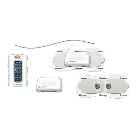
Patient Components StimRouter Lead The StimRouter Lead is flexible and approximately 15 cm (6 in.) in length. The lead has a stimulation end and a receiver end. The stimulation end is implanted near or at the targeted peripheral nerve and the receiver end is implanted near the skin surface. -
Page 39: Charging Socket And Charging Light
• Two snaps for EPT placement. • Two tabs for removing the StimRouter Electrode from the skin. • A liner to protect the gel pads on the back of the StimRouter Electrode. Snaps Tabs Gel Electrodes Figure 5-4: StimRouter Electrode (top and bottom views) Clinician’s Guide... -
Page 40: Patient Programmer
The StimRouter Electrode is disposable and can be reused by the same patient as long as the gel pads are intact and can fully adhere to the skin or for a maximum of four days of use. The typical lifespan of the StimRouter Electrode is two to four days, depending •... -
Page 41: Operating Modes
Operating Buttons Description Function On/Off Button Turns the system on and off. Selects standby, program and Mode Button stimulation mode. Used to increase or decrease Plus/Minus Buttons stimulation intensity and to select a stimulation program. Used to increase, decrease and Volume Buttons mute the sound level of the audio alerts. -
Page 42: Program Mode
Program Mode In program mode, a patient may select between different stimulation programs. Stimulation Mode In stimulation mode, the StimRouter components are stimulating the target treatment area. A patient can adjust the intensity level of stimulation. Charging Socket and Connection Port The Patient Programmer charging socket and the connection port are located at the bottom of the Patient Programmer, under the flexible cover. - Page 43 Clinician’s Guide...
-
Page 44: Chapter 6: Stimrouter Clinician Kit
StimRouter Clinician Kit The StimRouter Clinician Kit includes the following: • Clinician’s Programmer, Tablet with Software and Stylus • Clinician’s Programmer Micro SD Card • Clinician’s Programmer Charger • Tester • Clinician’s Reference Card • Clinician’s Manual • Programmer Connector Cable Clinician’s Programmer... - Page 45 Clinician’s Guide...
-
Page 46: Chapter 7: Device Description
Charger Figure 7-1: The Clinician’s Programmer and Patient Programmer connected Clinician’s Programmer The StimRouter Clinician’s Programmer is used to program, test and save stimulation parameters and programs on the StimRouter EPT and Patient Programmer. The Clinician’s Programmer is a Windows Tablet PC that comes with the StimRouter ®... -
Page 47: Operating Buttons
Micro SD Slot Contains the Clinician’s Programmer micro SD card. Touchscreen Display Used to navigate the StimRouter software, read statuses and enter data. Use the pointed end of the stylus to make contact with the display screen. Connector Port For use with the Programmer Connector Cable. -
Page 48: Tester
Operating Modes The StimRouter software has two operating modes: online and offline. Online. The StimRouter Clinician’s Programmer is online when connected to an operational StimRouter Patient Programmer and EPT. See Table 7-1. Offline. The StimRouter Clinician’s Programmer is offline when not connected to an operational StimRouter Patient Programmer and EPT. -
Page 49: Information Icon
• Add a new user. • Remove a user. • Change a user password. Table 7-1: StimRouter software operating modes and function descriptions Information Icon Used to communicate system status, error messages and troubleshooting solutions. When the icon is RED or YELLOW, press the icon for more information. See Figure 7-3. -
Page 50: Print Icon
GREEN when the StimRouter is online; GRAY when no Patient Programmer is detected. FLASHING RED when a Patient Programmer is connected and a correctable error has occurred (for example, RF communication failure). CONSTANT RED when a Patient Programmer is connected and an error has occurred. -
Page 51: Menu Bars And Menus
Menu Bar and Menus The StimRouter software has five navigation menus, which appear on the menu bar. See Figure 7-5. Figure 7-5: Menu bar Exit. Used to exit or logoff the StimRouter software. Patients. Used to open a patient record, add a new patient, modify a patient record or remove a patient record. - Page 52 Restore • Restore the Clinician’s Programmer database from automatic backup. • Restore the Clinician’s Programmer from manual backup. Table 7-2: StimRouter software navigation menus, navigation tabs and functions that can be performed from each menu/tab Chapter 7 - Device Description...
-
Page 53: Navigation Buttons
Clear • Delete characters in a field. Exit • Exit the StimRouter software. Login • Log into the StimRouter software. Log Off • Log off the StimRouter software. Modify • Modify an existing patient record. • Add a new patient record. -
Page 54: Intensity Level Bar
Intensity Level Bar Used to adjust stimulation intensity. Can be adjusted while stimulation is on or off. See Figure 7-6. Decrease 1 mA Increase 1 mA Decrease 5 mA Increase 5 mA Level Setting Figure 7- 6: Intensity level bar Program Bar Used to add, delete and view up to eight clinician-set stimulation programs, labeled A-H. -
Page 55: Stimulation Parameters
Stimulation Parameters Patients require tailored stimulation patterns to help control their pain. The StimRouter system features eight programmable parameters and can store up to eight stimulation programs on the Clinician’s Programmer, Patient Programmer and EPT. Timing parameters are specified in Table 7-4. Pulse parameters are specified in Table 7-5. - Page 56 Pulse Parameter Specification Balanced biphasic (pulse is hardware Pulse balanced — no DC component exists) Waveform Symmetric or Asymmetric 0-30 milliamperes peak, 1 milliampere Intensity* resolution (positive phase) Maximum Voltage 100V Maximum Output 12 milliamperes root mean square Maximum Charge 15 microcoulombs per phase Less than 1 milliampere root mean square Electrode Current Density...
- Page 57 Clinician’s Guide...
-
Page 58: Chapter 8: Clinician's Programmer Set-Up
Clinician’s Programmer Set-Up Connecting the Clinician’s Programmer and Programmer Connector Cable To connect the Clinician’s Programmer and Programmer Connector Cable: 1. Plug the Programmer Connector Cable into the connector port on the Clinician’s Programmer. Clinician’s Programmer Clinician’s Programmer Charger Programmer Connector Cable Clinician Programmer... -
Page 59: Connecting The Patient Programmer And Programmer Connector Cable
1. Turn the Clinician’s Programmer on by pressing the on/off button on the upper left corner of the Clinician’s Programmer. 2. If the login screen does not open automatically, then, press “Start” and then “StimRouter” to open the StimRouter software. Wait for the login screen to load. See Figure 8-3. Clinician’s Guide... - Page 60 Figure 8-3: The StimRouter software login screen 3. To log in, enter a user name and password, and then press the “Login” button. Note: Always log off the StimRouter software before leaving the Clinician’s Programmer unattended. Chapter 8 - Clinician’s Programmer Set-Up...
- Page 61 Clinician’s Guide...
-
Page 62: Chapter 9: Software Records And History
To add a new patient to the Clinician’s Programmer database: 1. Connect the Patient Programmer to the Clinician’s Programmer. 2. Connect the patient’s EPT to a StimRouter Electrode. See “Connecting the StimRouter Electrode and EPT” section of this guide. 3. If the EPT and Patient Programmer are unassigned, then the software should automatically prompt that no patient data was found on the system. -
Page 63: Copying A Record For An Existing Patient To An Unassigned System
To copy a record for an existing patient to an unassigned system: 1. Connect the Patient Programmer to the Clinician’s Programmer. 2. Connect the patient’s EPT to a StimRouter Electrode. See “Connecting the StimRouter Electrode and EPT” section of this guide. -
Page 64: Adding A Patient With An Assigned System
To add a patient with an assigned system to the Clinician’s Programmer database: 1. Connect the Patient Programmer to the Clinician’s Programmer. 2. Connect the patient’s EPT to a StimRouter Electrode. See “Connecting the StimRouter Electrode and EPT” section of this guide. -
Page 65: Modifying A Patient Record
Figure 9-4: Opening a patient record Modifying a Patient Record Note: “Modify” is only enabled in online mode, when the Clinician’s Programmer is connected to a working Patient Programmer and EPT. To modify a patient record: 1. From the Patient List, press the “Modify” button. 2. -
Page 66: Searching For A Patient Record
To remove a patient record: 1. Make certain that the Clinician’s Programmer is not connected to an operational Patient Programmer and EPT. 2. From the Patient List select the patient record to remove, and then press the “Remove” button. See Figure 9-6. 3. -
Page 67: Viewing A Usage History
Viewing a Usage History To view a usage history: 1. From the Patients List, select a patient and press the “Open” button. 2. Press “History” on the Menu Bar and then press the Usage Tab to open the Usage Log. 3. -
Page 68: Session History
2. Windows folder selection dialog will appear, select a folder where the file will be saved. Press OK to save. Session History Viewing a Session History To view a session history: 1. From the Patients List, select a patient and press the “Open” button. 2. -
Page 69: Printing/Saving A Session History
Printing/Saving a Session History To print a session history: 1. With the session detail window open, press the print icon. 2. Windows standard print dialog will appear. To save a session history: 1. Press the save icon on the Usage Log window. 2. -
Page 70: Chapter 10: Patient Set-Up And Programming Instructions
1. Obtain a new StimRouter Electrode. 2. Check the “Use by” date on the StimRouter Electrode box. 3. Do not remove the liner at this time. Set the StimRouter Electrode on a flat surface with the gel pads facing down. -
Page 71: Adhering The Stimrouter Electrode To The Skin
Figure 10 -1: StimRouter Electrode and EPT connecting Adhering the StimRouter Electrode to the Skin WARNING: Do not touch the gel pads of the StimRouter Electrode with both hands while stimulation is turned on. Serious injury could result from electrical current passing across the chest cavity. - Page 72 The center of the gel pad should be above the receiver end of the lead. See Figure 10- 4. If the StimRouter electrode is not directly over the receiver end of the lead, then stimulation may be uncomfortable or ineffective.
-
Page 73: Confirming Set-Up
Electrode is placed partially or wholly over a bandage or other obstruction, then skin irritation or tissue damage could occur during stimulation. 6. Firmly adhere the StimRouter Electrode to the skin, making sure that the electrode is in full contact with the skin. If the StimRouter Electrode is not firmly adhered to the skin and moves, then stimulation may become uncomfortable or ineffective. -
Page 74: Programming Instructions
StimRouter Electrode Figure 10-5: Removing the StimRouter Electrode 2. Attach the StimRouter Electrode liner to the gel pads. Without the liner attached, the gel pads on the back of the StimRouter Electrode will lose their adhesiveness. 3. Store the StimRouter electrode with the liner attached in the StimRouter Electrode carrying case. - Page 75 3. Press the “Test” button to test the stimulation settings; stimulation will turn on. 4. If needed, adjust the stimulation settings using the drop-down lists next to “Waveform”, “Phase Duration”, and “Pulse Rate”. Note: The stimulation settings have a constant ramp-up and ramp-down of 1 second, during which the patient may not feel any stimulation.
-
Page 76: Programming Time Settings
Figure 10-8: Press “Stop & Save” to stop testing and save the current stimulation settings 7. The program save date will appear on the Program Bar. Programming Time Settings To program time settings: 1. From the Stim Settings window, press the Time Settings Tab. 2. -
Page 77: Programs
4. The new program will be saved to the Clinician’s Programmer database, the Patient Programmer and the EPT. Note: The StimRouter software must be in online mode to add a program. Saving a Program To save a program to file: 1. -
Page 78: Deleting A Program
1. From the Stim Settings Window or Time Settings Window, select a program to delete. 2. Press the delete program icon on the Program Bar. See Figure 10-10. Note: The StimRouter software must be in online mode to delete a program. Printing a Program To print a program: 1. - Page 79 Clinician’s Guide...
-
Page 80: Chapter 11: Software Tools
System information can be found on the Info Tab of the Tools Menu. From the Info Tab users can look up the installed software version on all components of the StimRouter system. For example, “EPT SW VER: 1.0.0.4” indicates to the user that the EPT software version is 1.0.0.4. -
Page 81: User Administration
User Administration The StimRouter software supports two levels of users: users and administrators. Both users and administrators have access to the Info Tab of the Tools Menu. Administrators have extended authorizations and have access to the Users, Backup and Restore tabs of the Tools Menu. Administrators can define automatic backup options, manually back up the Clinician’s Programmer database, manually restore... -
Page 82: Removing A User/Administrator
When a memory card is installed and automatic backup is enabled, the Clinician’s Programmer will automatically back up the database periodically and whenever the StimRouter software is exited. Chapter 11 - Software Tools... -
Page 83: Enabling Automatic Database Backup
Enabling Automatic Database Backup To enable automatic database backup: 1. Press “Tools” on the Menu Bar, press the Backup Tab, and then check “Enable automatic database backup”. The Clinician’s Programmer database will back up once daily and each time the software is exited. See Figure 11-5. Figure 11- 5: Backing up the Clinician’s Programmer database Manually Backing Up the Database To manually back up the Clinician’s Programmer database:... - Page 84 Figure 11-6: Restoring the Clinician’s Programmer database 4. Select “From automatic backup” or “From manual backup”, and then choose a backup date and time from the drop-down lists. 5. Press the “Start Restore” button. Chapter 11 - Software Tools...
- Page 85 Clinician’s Guide...
-
Page 86: Chapter 12: Maintenance And Cleaning
StimRouter Electrode. Instruct patients to dispose of the StimRouter Electrode when any of the following occurs: • The gel pads start to peel off at the edges or detach from the StimRouter Electrode. • The gel pads appear worn or dirty. -
Page 87: Cleaning
Do not use detergents or other cleaning agents. Do not clean the gel pads on the back of the StimRouter Electrode. The screen of the Clinician Programmer can be cleaned using any commercially available screen cleaner for liquid crystal displays (LCD) and computer screens. -
Page 88: Disinfecting
3. As needed, use additional saturated disinfectant wipes or cloths to keep the component surface wet for 10 minutes. Note: Be sure to follow the Bioness instructions for the specified contact time to ensure an effective bacteria kill. Chapter 12 - Maintenance and Cleaning... - Page 89 Clinician’s Guide...
-
Page 90: Chapter 13: Troubleshooting
Troubleshooting The tables at the end of this section describe the visual indicators that may appear on the Clinician’s Programmer and Patient Programmer, and possible solutions for troubleshooting. In addition, this section describes solutions for the following scenarios that may arise during a programming session: •... -
Page 91: Registering The Patient Programmer/Ept
5. Press “Tools” on the Menu Bar and then press the Reset Tab. 6. Select “Reset the Patient Programmer” and press the “Reset” button. 7. The StimRouter software will detect the unregistered Patient Programmer and ask whether you want to register this Patient Programmer to an EPT now. - Page 92 In Process Complete Error Figure 13-2: StimRouter Patient Programmer operating buttons and RF registration status indicators 6. When the digital display shows the letter “C” and the RF icon turns GREEN for a few seconds, the registration procedure is complete.
-
Page 93: Patient Forgets Ept
Patient Brings New EPT and New Patient Programmer If a patient receives a replacement EPT and Patient Programmer, then the patient will need to return to the clinic to have their StimRouter system reprogrammed. The patient data stored on the Clinician’s Programmer database must be copied to the new EPT and Patient Programmer. -
Page 94: Testing The Ept
7. From the Patient List, select the patient’s record and press “Open”. Once the patient record is opened, all patient data except for history will copy to the patient’s new Patient Programmer and EPT. Testing the EPT The Tester is used to test the functionality of an EPT after the EPT has been programmed. -
Page 95: Troubleshooting Tables
• Charge the Clinician’s Programmer and verify that the charging LED Clinician’s Programmer Will is ON. Not Turn On • Contact Bioness or your local distributor. Table 13-2: Troubleshooting - Clinician’s Programmer Patient Programmer Indicator Problems/Solutions Battery Failure; Charger Failure;... - Page 96 FLASHES YELLOW • Charge the EPT. EPT Malfunction EPT Icon GLOWS RED and “E” appears in the • Contact Bioness or your local Digital Display distributor. EPT Temperature Error • The EPT is either too hot or too EPT Icon FLASHES RED cold and will cease activity until and “E”...
- Page 97 • Check to see if one of the Appears in the Digital buttons is stuck and, if so, try Display to release it. • Contact Bioness or your local distributor. Patient Programmer Battery Charge Level is Low Patient Programmer Icon FLASHES YELLOW •...
- Page 98 RF Icon FLASHES range, then turn the Patient Programmer off and back on. • Charge the EPT. • Re-register the components. • Contact Bioness or your local distributor. Table 13-6: Troubleshooting - Patient Programmer, RF icon Chapter 13 - Troubleshooting...
- Page 99 • Review the skin care instructions. Clean the skin with a damp cloth. • Change the StimRouter Electrode, if the skin is dry. • Trim hair from the StimRouter Electrode site. • Test the EPT using the tester. • Decrease the stimulation intensity level.
-
Page 100: Chapter 14: Technical Specifications
Technical Specifications Wireless (RF) Communications Specifications Capabilities • Communication between Patient Programmer and EPT RF Communication is used between the EPT and Patient Programmer, enabling the Clinician’s Programmer to perform the following functions: • Define stimulation parameters and programs (e.g., pulse width, amplitude) Functions •... -
Page 101: Troubleshooting Wireless Technology
Privacy of StimRouter Wireless Communication While the frequency band used by the StimRouter wireless system can be used by other users of the band, the privacy of the StimRouter wireless system is ensured by: • The unique ID of paired components. -
Page 102: Chapter 15: Appendix - Emi Tables
(EMC) in accordance with International Electrotechnical Committee (IEC) 60601-1-2. The following tables provide information regarding the EMC testing and guidance for safe use of the system. The StimRouter system should be configured and used in accordance with the instructions provided in this manual. - Page 103 Electromagnetic Environment - Emissions Test Compliance Guidance The StimRouter system uses RF energy for short-range communications. Therefore, its RF emissions are very low, about 100 times lower than a RF emissions commercially available cell phone. Group 1 Though unlikely, portable and mobile...
-
Page 104: Guidance And Manufacturer's Declaration Electromagnetic Immunity
Guidance and Manufacturer’s Declaration Electromagnetic Immunity The StimRouter system is intended for use in the electromagnetic environment specified below. The user of the StimRouter system should assure that it is used in such an environment. Electromagnetic IEC 60601 Test Compliance... - Page 105 A.C. mains voltage prior to application of the test level. Guidance and Manufacturer’s Declaration Electromagnetic Immunity The StimRouter system is intended for use in the electromagnetic environment specified below. The customer or the user of the StimRouter system should assure that it is used in such an environment. Clinician’s Guide...
- Page 106 Test Level Level Guidance Portable and mobile RF communications equipment should be used no closer to any part of the StimRouter system, including cables, than the recommended separation distance calculated from the equation applicable to the frequency of the transmitter.
-
Page 107: Recommended Separation Distances For Device
To assess the electromagnetic environment due to fixed RF transmitters, an electromagnetic site survey should be considered. If the measured field strength in the location in which the StimRouter system is used exceeds the applicable RF compliance level above, the StimRouter system should be observed to verify normal operation. - Page 108 Rated Maximum Separation Distance According to Output Power of Frequency of Transmitter Transmitter 150 kHz 80 MHz 800 MHz to 80 MHz to 800 MHz to 2.5 GHz d = 1.2√P d = 0.4√P d = 2.3√P 39 ft. 4 in. 13 ft.
Need help?
Do you have a question about the StimRouter and is the answer not in the manual?
Questions and answers