Bioness StimRouter Clinician Manual
Neuromodulation system
Hide thumbs
Also See for StimRouter:
- Clinicians manual (108 pages) ,
- User manual (90 pages) ,
- User's reference card (2 pages)
Table of Contents
Advertisement
Quick Links
Download this manual
See also:
User Manual
Advertisement
Table of Contents
Troubleshooting

Related Manuals for Bioness StimRouter


Summary of Contents for Bioness StimRouter
- Page 1 Clinician’s Guide...
- Page 2 Disclaimer Bioness Inc. shall not be liable for any injury or damage suffered by any person, either directly or indirectly, as a result of the unauthorized use or repair of Bioness Inc. products. Bioness does not accept any responsibility for any damage caused to its products, either directly or indirectly, as a result of use and/or repair by unauthorized personnel.
- Page 3 List of Symbols Caution Warning Class II Equipment (Double Insulated) Type BF Applied Part(s) Non-Ionizing Radiation Date of Manufacture Manufacturer This Product Must Not Be Disposed of with Other Household Waste Consult Instructions for Use Re-Order Number Lot Number Serial Number Single Patient Use Storage Temperature Complies with the European Union Medical Device Directive...
-
Page 4: Table Of Contents
Implantation Setting ........................4 Patient Screening ........................4 Warnings ........................... 5 Magnetic Resonance Imaging (MRI) Warnings and Precautions ........... 5 StimRouter External Component Restrictions ..............5 MRI Information....................... 5 MRI-Related Heating: Supplemental Information ............8 Image Artifacts ........................ 9 Induced Currents ......................10 Potential Adverse Events ....................10... - Page 5 Storage and Handling ......................15 Adverse Effects ........................15 Risks Related to the Implant Procedure ................16 Risks Related to Stimulation....................16 Additional Risks Related to the StimRouter System ............16 Chapter 3: Clinical Experience .................17 Chapter 4: Environmental Conditions that Affect Use........... 19 Storage and Handling.......................19 Radio Communication Information ...................19...
- Page 6 ..............Connecting the Clinician’s Programmer and Configuration Cradle .......... 41 Charging the Clinician’s Programmer ..................41 Connecting the Patient Programmer and Configuration Cradle..........42 Logging into the StimRouter Software ..................43 Chapter 9: Software Records and History ..............Patient Records........................45 Adding a New Patient ......................
- Page 7 Chapter 10: Patient Set-Up and Programming Instructions ........Preparing the Patient’s Skin ....................55 Connecting the StimRouter Electrode and EPT ............... 55 Adhering the StimRouter Electrode to the Skin ............... 56 Confirming Set-Up ........................58 Removing the StimRouter Electrode ..................58 Programming Instructions ....................... 59 Programming Stimulation Settings ..................
- Page 8 Replacing the Clinician’s Programmer Battery ..............75 Replacing the Patient Programmer Battery ................. 76 Cleaning ...........................77 Disinfecting ..........................77 Electronic Components......................77 Clinician Kit Carrying Case ....................77 Chapter 13: Troubleshooting ..................Patient Forgets Patient Programmer ..................79 Using a Clinic Patient Programmer..................79 Registering the Patient Programmer/EPT ................
- Page 9 Clinician’s Guide...
-
Page 10: Chapter 1: Introduction
Lead Introducer Kit, package contents, device specifications and the StimRouter implant procedure. Refer to the StimRouter User’s Guide for a full description of the StimRouter User Kit, StimRouter Electrode, External Pulse Transmitter (EPT), Patient Programmer, external accessories, package contents, device specifications and instructions for use. - Page 11 Clinician’s Guide...
-
Page 12: Chapter 2: Warnings And Cautions
StimRouter Neuromodulation System. Physicians should review the warnings and precautions and instructions for use with the patient. If at any time the physician or patient is concerned about the safety or effectiveness of the StimRouter system, then call Bioness at (800) 211-9136 or your local distributor. -
Page 13: Implantation Setting
Implantation Setting The StimRouter Lead should be implanted in an appropriately outfitted physician office, outpatient surgical center or hospital surgical center. Fluoroscopy and/or ultrasound should be available if deemed necessary and be used at the implanting physician’s discretion. -
Page 14: Warnings
When using head transmit RF coil, do not exceed head SAR of 3.2 W/Kg. • Do not place a local RF transmit coil directly over the implanted StimRouter Lead. StimRouter External Component Restrictions All external components of the StimRouter system are contraindicated for the MRI environment. - Page 15 • When all or part of the StimRouter Lead is either (a) less than 50 cm (19.7 in.) from the center of the MR system’s bore; or (b) less than 16 cm (6.3 in.) from the end of the RF coil, whichever is the furthest distance from the center of the bore (i.e., referred to as the “Reduced Zone”), reduced values of WB SAR and...
- Page 16 Lead is at least 50 cm away from the center of the MR system’s bore (the iso-center) and at least 16 cm outside of the MR coil measured from the edge of the MR coil. In Figure 2-1, the StimRouter Lead (B) implant is inside the “Reduced Zone.”...
-
Page 17: Mri-Related Heating: Supplemental Information
SAR of 2 W/kg predicts a worst-case heating of an implanted StimRouter Lead in the patient during MRI of less than 2°C, provided that the entire StimRouter Lead implant is outside of the Reduced Zone. -
Page 18: Image Artifacts
SAR of 2 W/kg predicts a worst-case heating of an implanted StimRouter Lead in the patient during MRI of less than 1°C, provided that the entire StimRouter Lead implant is outside of the Reduced Zone. -
Page 19: Induced Currents
Lead is located outside of the Reduced Zone. Potential Adverse Events Use of MRI could result in excessive heating of the StimRouter Lead if the MRI conditions of use are not followed. Induced voltages in the lead may occur, possibly causing uncomfortable levels of neurostimulation. -
Page 20: Flammable Fuel, Chemicals Or Environment
Electromagnetic Compatibility Warnings Medical Devices/Therapies Operation of the StimRouter system in close proximity (e.g., 1 meter) to shortwave or microwave therapy equipment may produce instability in the EPT output. The following medical therapies or procedures may turn stimulation off, may cause permanent... -
Page 21: Electrosurgery Devices
To minimize interference, maintain a minimum safe separation distance of 15 cm (6 in.) between the StimRouter system and all other electronic devices. See the Troubleshooting section for help. See the Appendix for more information. -
Page 22: Cell Phones
For Single Patient Use Only The StimRouter Electrode is meant to be worn only by the patient for whom it is prescribed and in the location for which it is prescribed. The StimRouter Electrode should not be adhered to any other person or any other place on the patient’s body. -
Page 23: Keep Out Of Reach Of Children
The StimRouter components should be kept out of the reach of children. Skin Abnormalities Do not adhere the StimRouter Electrode to sites that are swollen, infected or inflamed, or that have skin eruptions such as phlebitis, thrombophlebitis and varicose veins. Do not adhere the StimRouter Electrode to skin that is breached. -
Page 24: Expiration Date
Do not apply the StimRouter Electrode over skin folds, scarred tissue, irritated skin, uneven skin surfaces or broken skin. • Always inspect the gel pads on the back of the StimRouter Electrode before use. Do not apply the StimRouter electrode if the gel pads appear dried out, worn, dirty or irregular. •... -
Page 25: Risks Related To The Implant Procedure
Risks Related to Stimulation • Operation of the StimRouter components may cause increased pain in an area other than the lead site. This pain may be caused by stimulation of the tissue surrounding the stimulation electrodes (e.g., skin, fascia and muscle). -
Page 26: Chapter 3: Clinical Experience
Ninety-four (94) subjects with intractable chronic pain were enrolled in the study, each of whom was implanted with a StimRouter Lead. Forty-five (45) subjects were randomized into the treatment (active stimulation) group, and 49 subjects were randomized into the control (non-stimulation) group. - Page 27 Because effective blinding is difficult to achieve in nerve stimulation studies, there was risk of the placebo effect in this study, which could cause the study results to overstate the difference in benefit between the control and treatment groups. Clinician’s Guide...
-
Page 28: Chapter 4: Environmental Conditions That Affect Use
Do not store StimRouter components in a car where they can be exposed to extreme hot or cold temperatures. Temperature extremes can damage the StimRouter components. -
Page 29: Conformity Certification
Changes or modifications to components not expressly approved by Bioness could void the user’s authority to operate the equipment. Conformity Certification The StimRouter complies with Part 15 of the FCC Rules. Operation is subject to the following two conditions: 1. This device may not cause harmful interference, and 2. -
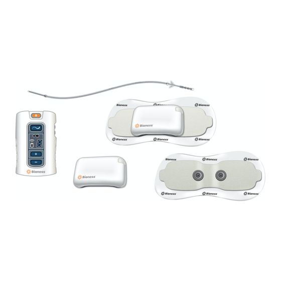
Page 30: Chapter 5: Patient Components
Patient Components StimRouter Lead The StimRouter Lead is flexible and approximately 15 cm (6 in.) in length. The lead has a stimulation end and a receiver end. The stimulation end is implanted near or at the targeted peripheral nerve and the receiver end is implanted near the skin surface. The receiver end receives the stimulation signal from the EPT and then sends the signal through the lead to the stimulation end. -
Page 31: Stimrouter Electrode
StimRouter Electrode The StimRouter Electrode features: (See Figure 5-4) • Two gel pads that adhere the StimRouter Electrode to the skin. The gel pads also transmit the stimulation signal from the EPT to the receiver end of the lead. •... -
Page 32: Patient Programmer
The StimRouter Electrode is disposable and can be reused by the same patient as long as the gel pads are intact and can fully adhere to the skin or for a maximum of four days of use. The typical lifespan of the StimRouter Electrode is two to four days, depending on: •... - Page 33 Program Mode In program mode, a patient may select between different stimulation programs. Stimulation Mode In stimulation mode, the StimRouter components are stimulating the target treatment area. A patient can adjust the intensity level of stimulation. Clinician’s Guide...
- Page 34 Charging Socket and Connection Port The Patient Programmer charging socket and the connection port are located at the bottom of the Patient Programmer, under the flexible cover. See Figure 5-6. The connection port is used to connect the Patient Programmer to the Configuration Cradle and Clinician’s Programmer during a programming session.
- Page 35 Clinician’s Guide...
-
Page 36: Chapter 6: Stimrouter Clinician Kit
StimRouter Clinician Kit The StimRouter Clinician Kit includes the following: • Clinician’s Programmer with Software • Clinician’s Programmer Memory Card • Clinician’s Programmer Charger • Configuration Cradle • Tester • Clinician’s Reference Card • HP product literature Clinician’s Programmer Charger Tester Clinician’s Programmer... - Page 37 Clinician’s Guide...
-
Page 38: Chapter 7: Device Description
The StimRouter Clinician’s Programmer is used to program, test and save stimulation parameters and programs on the StimRouter EPT and Patient Programmer. The Clinician’s Programmer is a portable personal digital assistant (PDA) that comes with the StimRouter software and a memory card installed. - Page 39 CAUTION: Risk of explosion if battery is replaced by an incorrect type. Dispose of used batteries according to local regulation. Touchscreen Display Used to navigate the StimRouter software, read statuses and enter data. Use the pointed end of the stylus to make contact with the display screen. Use only the stylus. Connector Port For use with the connector cable on the Configuration Cradle.
-
Page 40: Tester
Bioness Inc. proprietary StimRouter software. Do not use the Clinician’s Programmer for any purpose other than that described in this manual. Third-party software packages are not supported and may interfere with proper operation of the StimRouter components, thus voiding the warranty. -
Page 41: Stimrouter Software
Online. The StimRouter Clinician’s Programmer is online when connected to an operational StimRouter Patient Programmer and EPT. See Table 7-1. Offline. The StimRouter Clinician’s Programmer is offline when not connected to an operational StimRouter Patient Programmer and EPT. See Table 7-1. -
Page 42: Information Icon
RED or YELLOW, press the icon with the stylus for more information. See Figure 7-3. Information Icon Figure 7-3. Location of the information icon. • GREEN when the StimRouter is online; GRAY when no Patient Programmer is detected. • FLASHING RED with “i” in the center when a Patient Programmer is connected and a correctable error has occurred (for example, RF communication failure). -
Page 43: Menu Bar And Menus
Menu Bar and Menus The StimRouter software has five navigation menus, which appear on the menu bar. See Figure 7-5. Figure 7-5. Menu bar. Exit. Used to exit or logoff the StimRouter software. Patients. Used to open a patient record, add a new patient, modify a patient record or remove a patient record. - Page 44 Restore • Restore the Clinician’s Programmer database from automatic backup. • Restore the Clinician’s Programmer from manual backup. Table 7-2. StimRouter software navigation menus, navigation tabs and functions that can be performed from each menu/tab. Chapter 7 - Device Description...
-
Page 45: Navigation Buttons
• Add a new user (enabled for administrators only). Open • Open an existing patient record. Print • Print the specified report to a Bioness-approved Bluetooth printer or to a PDF file on the memory (SD) card. Remove • Remove an existing patient record. -
Page 46: Intensity Level Bar
Intensity Level Bar Used to adjust stimulation intensity. Can be adjusted while stimulation is on or off. See Figure 7-6. Increase 5 mA Increase 1 mA Level Setting Decrease 5 mA Decrease 1 mA Figure 7-6. Intensity level bar. Program Bar Used to add, delete and view up to eight clinician-set stimulation programs, labeled A-H. -
Page 47: Search Bars
Figure 7-8. Search bars for usage log. Stimulation Parameters Patients require tailored stimulation patterns to help control their pain. The StimRouter system features eight programmable parameters and can store up to eight stimulation programs on the Clinician’s Programmer, Patient Programmer and EPT. Timing parameters are specified in Table 7-4. - Page 48 Pulse Parameter Specification Intensity* 0-30 milliamperes peak, 1-milliampere resolution (positive phase) Maximum Voltage 100 volts Maximum Output 7 milliamperes root mean square, 40 volts root mean square Maximum Charge Allowed 10 microcoulombs per phase Electrode Current Density Less than 1 milliampere root mean square per centimeter2 Positive Phase Duration** 70, 100, 150, 200, 250, 300, 350, 400, 450, 500...
- Page 49 Clinician’s Guide...
-
Page 50: Chapter 8: Clinician's Programmer Set-Up
Clinician’s Programmer Set-Up Connecting the Clinician’s Programmer and Configuration Cradle To connect the Clinician’s Programmer and Configuration Cradle: 1. Orient the Clinician’s Programmer in the Configuration Cradle with the touchscreen facing up and the connector port facing left. See Figure 8-1. Clinician’s Programmer Clinician Programmer Charger... -
Page 51: Connecting The Patient Programmer And Configuration Cradle
When the Clinician’s Programmer is fully charged, the indicator light next to the On/Off button will be GREEN. WARNING: Use only the Clinician’s Programmer charger included in the StimRouter Clinician Kit (Manufacturer Model No. PSC11R-050(FXC)-R (HP P/N 395250-001). -
Page 52: Logging Into The Stimrouter Software
Clinician’s Programmer. 2. If the login screen does not open automatically, then, using the stylus, press “Start” and then “StimRouter” to open the StimRouter software. Wait for the login screen to load. See Figure 8-3. Figure 8-3. The StimRouter software login screen. - Page 53 Clinician’s Guide...
-
Page 54: Chapter 9: Software Records And History
To add a new patient to the Clinician’s Programmer database: 1. Connect the Patient Programmer to the Clinician’s Programmer. 2. Connect the patient’s EPT to a StimRouter Electrode. See “Connecting the StimRouter Electrode and EPT” section of this guide. 3. If the EPT and Patient Programmer are unassigned, then the software should automatically prompt that no patient data was found on the system. -
Page 55: Copying A Record For An Existing Patient To An Unassigned System
To copy a record for an existing patient to an unassigned system: 1. Connect the Patient Programmer to the Clinician’s Programmer. 2. Connect the patient’s EPT to a StimRouter Electrode. See “Connecting the StimRouter Electrode and EPT” section of this guide. -
Page 56: Adding A Patient With An Assigned System
2. Connect the patient’s EPT to a StimRouter Electrode. See “Connecting the StimRouter Electrode and EPT” section of this guide. 3. The StimRouter software will automatically prompt that a new patient was found and to add the patient to the clinician programmer database. Press “OK”. See Figure 9-3. -
Page 57: Opening A Patient Record
Opening a Patient Record Note: When the Clinician’s Programmer is in online mode and connected to an assigned Patient Programmer and an EPT, then only the patient record corresponding to those components can be opened. If the Clinician’s Programmer is in offline mode, then any patient record can be opened and viewed. -
Page 58: Removing A Patient Record
Figure 9-5. Modifying a patient record. Removing a Patient Record Note: “Remove” is only enabled in offline mode. To remove a patient record: 1. Make certain that the Clinician’s Programmer is not connected to an operational Patient Programmer and EPT. 2. -
Page 59: Searching For A Patient Record
Searching for a Patient Record To search for a patient record: 1. Make certain that the Clinician’s Programmer is not connected to an operational Patient Programmer and EPT. 2. From the Patient List select the “Search by” drop-down list and pick a search criterion. 3. -
Page 60: Printing A Usage History
4. In the “From”, “To” and “Interval” drop-down lists (top of screen), select a from date, a to date and an interval for viewing, and then press the double arrow. The usage history will open. Note: Last Int. - Intensity in mA when the system was turned off the last time that interval. P. -
Page 61: Session History
Session History Viewing a Session History To view a session history: 1. From the Patients List, select a patient and press the “Open” button. 2. Press “History” on the Menu Bar and then press the Sessions Tab, select a session to view, and then press the “View”... -
Page 62: Printing A Session History
Printing a Session History To print a session history: 1. With the session detail window open, press the print icon. 2. From the “Printer” drop-down list, select the installed printer or “Adobe PDF file,” and then press the “Print” button. Note: Selecting “Adobe PDF file”... - Page 63 Clinician’s Guide...
-
Page 64: Chapter 10: Patient Set-Up And Programming Instructions
1. Obtain a new StimRouter Electrode. 2. Check the “Use by” date on the StimRouter Electrode box. 3. Do not remove the liner at this time. Set the StimRouter Electrode on a flat surface with the gel pads facing down. -
Page 65: Adhering The Stimrouter Electrode To The Skin
1. Remove the liner and store it in the StimRouter Electrode Carrying Case. See Figure 10-2. Figure 10-2. Remove the StimRouter Electrode Liner. 2. Visually inspect the gel pads on the back of the StimRouter Electrode. Make sure the gel is smooth and the gel pads are not dry, worn or dirty. - Page 66 Note: The effectiveness of the stimulation is sensitive to the alignment and rotation of the StimRouter electrode in relation to the receiver end of the lead. If the alignment of the StimRouter electrode changes, the stimulation intensity may need to be adjusted.
-
Page 67: Confirming Set-Up
Patient Programmer, EPT and StimRouter Electrode. Removing the StimRouter Electrode To remove the StimRouter Electrode: 1. Make certain that stimulation is turned off. Then grasp the tab on the StimRouter Electrode and gently pull away from the skin. See Figure 10-5. StimRouter Electrode Figure 10-5. -
Page 68: Programming Instructions
This section describes how to program stimulation and time settings, and how to add a program, view a program, delete a program and print a program. Programming can begin once the StimRouter Electrode with EPT attached is adhered to the skin, the Clinician’s Programmer and Patient Programmer are connected, and the patient’s record is added. - Page 69 5. Slowly increase the intensity to a level that is tolerable for the patient and achieves paresthesia. Note: If the combination of parameters or intensity level exceeds the maximum charge level allowed (10 microcoulombs per phase), then a warning will appear with directions to reduce the total charge.
-
Page 70: Programming Time Settings
Programming Time Settings To program time settings: 1. From the Stim Settings window, press the Time Settings Tab. 2. The default time setting is constant stimulation. When “Constant Stim” is checked, “Time On” and “Time Off” are disabled; “Ramp Up” and “Total Time” can be adjusted. See Figure 10-9. -
Page 71: Programs
1. From the Stim Settings Window or Time Settings Window press the add program icon on the Program Bar. See Figure 10-10. 2. The new program Stim Settings window will open with default settings. The StimRouter software can support up to eight stimulation programs, labeled (A-H) which will appear in the Program Bar. -
Page 72: Deleting A Program
1. From the Stim Settings Window or Time Settings Window, select a program to delete. 2. Press the delete program icon on the Program Bar. See Figure 10-10. Note: The StimRouter software must be in online mode to delete a program. Printing a Program To set up a connection to a printer see the “Bluetooth Printer Set-Up”... - Page 73 Clinician’s Guide...
-
Page 74: Chapter 11: Software Tools
System information can be found on the Info Tab of the Tools Menu. From the Info Tab users can look up the installed software version on all components of the StimRouter system. For example, “EPT SW VER: 1.0.0.4” indicates to the user that the EPT software version is 1.0.0.4. -
Page 75: User Administration
Figure 11-2. Reset Patient Programmer and EPT window. User Administration The StimRouter software supports two levels of users: users and administrators. Both users and administrators have access to the Info Tab of the Tools Menu. Administrators have extended authorizations and have access to the Users, Backup and Restore tabs of the Tools Menu. - Page 76 Figure 11-3. Adding a user/administrator. Figure 11-4. Add new user window. Chapter 11 - Software Tools...
-
Page 77: Removing A User/Administrator
“Change Password” button. 2. Enter and confirm the new user password, and then press the “OK” button. Note: Bioness recommends that passwords be changed at least every three months. Clinician’s Programmer Database Backup and Restore Administrators can back up the Clinician’s Programmer database to the memory card automatically or manually at any time. -
Page 78: Enabling Automatic Database Backup
Enabling Automatic Database Backup To enable automatic database backup: 1. Press “Tools” on the Menu Bar, press the Backup Tab, and then check “Enable automatic database backup”. The Clinician’s Programmer database will back up once per day and each time the software is exited. See Figure 11-6. Figure 11-6. -
Page 79: Bluetooth Printer Set-Up
3. From the “Restore from” drop-down list, select “SD Card”. See Figure 11-7. Figure 11-7. Restoring the Clinician’s Programmer database. 4. Select “From automatic backup” or “From manual backup”, and then choose a backup date and time from the drop-down lists. 5. - Page 80 Figure 11-8. Connections tab window. Figure 11-9. Bluetooth: general tab window. 4. The Bluetooth Manager screen will open. Press “New”. See Figure 11-10. Figure 11-10. Bluetooth Manager screen. (Your screen icons may vary.) Chapter 11 - Software Tools...
- Page 81 5. The Connection Wizard will open. Press “Explore a Bluetooth device”. See Figure 11-11. Figure 11-11. Connection Wizard window. 6. Wait for the Bluetooth connection to process. Select the desired printer icon and then press the “Next” arrow. 7. Press “Serial Port” under “Service Selection” and then the “Next” arrow. See Figure 11-12. Figure 11-12.
- Page 82 Device Pairing To pair the Clinician’s Programmer with a Bluetooth printer: 1. From the Bluetooth Manager screen, press “Menu”. See Figure 11-13. Figure 11-13. Bluetooth Manager screen. (Your screen icons may vary.) 2. From the pop-up menu, press “Paired Devices” and then “Add”. 3.
- Page 83 5. Enter “0000” in the “Passkey” field and press the “ok” button. See Figure 11-15. Figure 11-15. “Passkey” field. 6. Bluetooth printer setup and pairing is complete. Clinician’s Guide...
-
Page 84: Chapter 12: Maintenance And Cleaning
StimRouter Electrode. Instruct patients to dispose of the StimRouter Electrode when any of the following occurs: • The gel pads start to peel off at the edges or detach from the StimRouter Electrode. • The gel pads appear worn or dirty. -
Page 85: Replacing The Patient Programmer Battery
Replacing the Patient Programmer Battery The Patient Programmer battery should be replaced approximately every two years. WARNING: Use only a rechargeable 1.2-volt NiMH AAA battery (900, 1000 or 1100 milliampere- hours). A non-rechargeable battery can damage and overheat the Patient Programmer. Overheating may lead to tissue injury or burns. -
Page 86: Cleaning
Cleaning All StimRouter Clinician Kit components may be cleaned by carefully wiping them with a damp cloth using water only. Do not use detergents or other cleaning agents. Do not clean the gel pads on the back of the StimRouter Electrode. - Page 87 4. Use additional new wipes or cloths, as needed, to keep the entire surface of the carrying case wet with 70% IPA for 10 minutes. Note: Be sure to follow the Bioness instructions for the specified contact time to ensure an effective bacteria kill.
-
Page 88: Chapter 13: Troubleshooting
Troubleshooting The tables at the end of this section describe the visual indicators that may appear on the Clinician’s Programmer and Patient Programmer, and possible solutions for troubleshooting. In addition, this section describes solutions for the following scenarios that may arise during a programming session: •... -
Page 89: Registering The Patient Programmer/Ept
5. Press “Tools” on the Menu Bar and then press the “Reset Patient Programmer/EPT” button. 6. Select “Reset the Patient Programmer” and press the “Reset” button. 7. The StimRouter software will detect the unregistered Patient Programmer and ask whether you want to register this Patient Programmer to an EPT now. See Figure 13-1. - Page 90 5. The Patient Programmer digital display should show two ALTERNATING GREEN ARCHES, indicating registration is in progress. On/Off Button Mode Button Volume Buttons Plus/Minus Buttons Unregistered In Process Complete Error Figure 13-2. StimRouter Patient Programmer operating buttons and RF registration status indicators. Chapter 13 - Troubleshooting...
-
Page 91: Patient Forgets Ept
If a patient receives a replacement EPT and Patient Programmer, then the patient will need to return to the clinic to have their StimRouter system reprogrammed. The patient data stored on the Clinician’s Programmer database must be copied to the new EPT and Patient Programmer. - Page 92 4. The StimRouter software will detect the unregistered Patient Programmer and ask whether you want to register this Patient Programmer to an EPT now. 5. Press “Yes”. 6. Once the Patient Programmer and EPT are registered, press “OK”. 7. From the Patient List, select the patient’s record and press “Open”. Once the patient record is opened, all patient data except for history will copy to the patient’s new Patient Programmer...
-
Page 93: Troubleshooting Tables
• Charge the Clinician’s Programmer and verify that the amber LED is ON. If the light does not turn on, refer to the HP instructions for use. • Contact Bioness or your local distributor. Table 13-2. Troubleshooting - Clinician’s Programmer. Patient Programmer Indicator... - Page 94 EPT Icon FLASHES Faulty Electrode Contact • Turn off the Patient Programmer. RED and Intensity Level • Remove the StimRouter Electrode from the skin. FLASHES in the Digital • Check to see that the protective covers were Display removed from the StimRouter Electrode.
- Page 95 Appears in the Digital Display • Check to see if one of the buttons is stuck and, if so, try to release it. • Contact Bioness or your local distributor. Patient Programmer Icon Patient Programmer Battery Charge Level is Low FLASHES YELLOW •...
- Page 96 • If the components are within range, then turn the Patient Programmer off and back on. • Charge the EPT. • Re-register the components. • Contact Bioness or your local distributor. Table 13-6. Troubleshooting - Patient Programmer, RF icon. Chapter 13 - Troubleshooting...
- Page 97 Solutions EPT and Stimulation Stimulation Not As Effective As Usual • Check the position of the StimRouter Electrode, it should be over the receiver end of the lead. • Make sure the StimRouter Electrode is securely adhered to the skin.
-
Page 98: Chapter 14: Technical Specifications
Technical Specifications Wireless (RF) Communications Specifications Capabilities • Communication between the Patient Programmer and EPT • Communication between the Clinician’s Programmer and Bluetooth- enabled printer Functions RF Communication is used between the EPT and Patient Programmer, enabling the Clinician’s Programmer to perform the following functions: •... - Page 99 Locations and The Patient Programmer and EPT communicate when an object-free line Ranges of sight is available, up to 7 m distance between them. The communication range will be shortened if conductive objects, such as metal or the human body, are in the communication path between the Patient Programmer and EPT.
-
Page 100: Troubleshooting Wireless Technology
Report problems to Bioness or your local distributor. Privacy of StimRouter Wireless Communication While the frequency band used by the StimRouter wireless system can be used by other users of the band, the privacy of the StimRouter wireless system is ensured by: •... - Page 101 Clinician’s Guide...
-
Page 102: Chapter 15: Appendix - Emi Tables
Stimulation control may be delayed. Maintain a minimum safe separation distance of 15 cm (6 in.) between the StimRouter system and all other electronic devices. If interference is suspected or anticipated, distance yourself from the source of interference. - Page 103 Guidance and Manufacturer’s Declaration Electromagnetic Emissions The StimRouter system is intended for use in the electromagnetic environment specified below. The customer or the user of the StimRouter system should assure that it is used in such an environment. Emissions Test...
- Page 104 Guidance and Manufacturer’s Declaration Electromagnetic Immunity The StimRouter system is intended for use in the electromagnetic environment specified below. The user of the StimRouter system should assure that it is used in such an environment. IEC 60601 Test Electromagnetic Environment...
- Page 105 Guidance and Manufacturer’s Declaration Electromagnetic Immunity The StimRouter system is intended for use in the electromagnetic environment specified below. The customer or the user of the StimRouter system should assure that it is used in such an environment. IEC 60601 Test...
- Page 106 RF transmitters, an electromagnetic site survey should be considered. If the measured field strength in the location in which the StimRouter system is used exceeds the applicable RF compliance level above, the StimRouter system should be observed to verify normal operation. If abnormal performance is observed, additional measures may be necessary, such as reorienting or relocating the StimRouter system.
- Page 107 25103 Rye Canyon Loop Valencia, CA 91355 USA Telephone: (800) 211-9136 Website: www.bioness.com Rx Only ©2016 Bioness Inc. StimRouter , Bioness, the Bioness Logo and LiveOn are trademarks of Bioness Inc. | www.bioness.com ™ ® ® 602-00631-001 Rev. B 03/2016...
Need help?
Do you have a question about the StimRouter and is the answer not in the manual?
Questions and answers