
Related Manuals for Bioness BITS


Summary of Contents for Bioness BITS
- Page 1 BITS Supplemental Guide Bedside & Mobile Configurations Bedside Table Configuration Mobile Cart Configuration...
- Page 3 The Bioness Integrated Therapy System (BITS) is a hardware and software platform using touchscreen technology that allows for patient interaction with different software programs. BITS is intended to challenge and assess the abilities of individuals, including those with deficits resulting from traumatic injuries and movement disorders as well as competitive athletes.
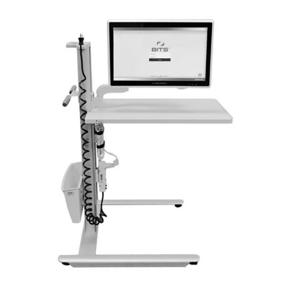
- Page 4 The BITS Mobile Configuration consists of a Mobile Stand with locking casters and an all-in-one Touchscreen PC with the BITS software applications. Touchscreen PC Power Cord Holder Height Adjustment Handle Rear Handle Power Adaptor & Power Adaptor Mount Power Cord...
-
Page 5: Indications For Use
Indications For Use The Bioness Integrated Therapy System (BITS) is intended to challenge and assess the physical, visual, auditory, and cognitive abilities of individuals, including those with deficits resulting from traumatic injuries and movement disorders as well as competitive athletes. - Page 6 Warnings • Do not move the Bioness Integrated Therapy System over obstacles on the floor or over uneven or soft surfaces. Doing so could cause the equipment to fall causing damage and/or injury. • Do not use the Bioness Integrated Therapy System near strong electromagnetic fields (e.g. MRI).
- Page 7 BITS Bedside & Mobile Configurations Component List The components for the BITS product consists of two different kits: The Hardware Kit and the Computer Kit. Do not start the installation process until both kits have been received. BITS Bedside Configuration Hardware Kit: 117-00207-001...
- Page 8 BITS Mobile Configuration Hardware Kit: 117-00208-001 Description Illustration (Reference Only) Quantity Mobile Stand with attached articulating arm and VESA mount and accessory bin Power Adapter Mount Power Strip with Coiled Cord...
- Page 9 612-00848-001 Note: Verify that all components have been received. Do not start the installation process if any of the listed components are missing. For technical support contact Bioness Client Support Department at 800.211.9136, Option 3 or your Bioness Sales Representative.
-
Page 11: Tools Needed For Installation
Tools Needed for Installation The list below includes items needed to install the BITS. The tools are not provided with the system. • 3/4” Socket Wrench • 1/2” Socket Wrench • 13 mm Wrench • 1/8” Allen Wrench • 5/32” Allen Wrench •... - Page 12 4. Slide the top Mounting Screws into the slots on the top of the VESA Mounting Plate on the Variable Height Arm. See Figure 4. Figure 4: Top Mounting Screws Inserted into VESA Mounting Plate. Caution: The Variable Height Arm is designed to dynamically support the weight of the Touchscreen PC. The arm may move down as the weight of the Touchscreen PC is transferred to it.
- Page 13 Touchscreen Mount Adjustment 1. To adjust the CW and CCW rotational tension, use a 13 mm wrench to adjust the hex nut on the back of the VESA Mount. See Figure 6. Figure 6: Rotational Tension Adjustment 1. To adjust the forward and backward tilting tension, use a 5/32” allen wrench adjust the bolt on the VESA Mount.
-
Page 14: Cable Management
Bedside Configuration Installation Instructions Cable Management 1. Remove the protective cover below the Horizontal Extension Arm near the Variable Height Column. See Figure 9. Figure 9: Remove Protective Cover 2. Thread the Power Cord through the space between the Bedside Table and the Variable Height Column. See Figure 10. - Page 15 4. Thread the Power Cord through the Cable Management Cover, and reattach it to the bottom of the Horizontal Extension Arm. See Figure 11. Figure 11: Reattach the Cable Management Cover 5. Insert the Power Cord in the Cable Clip on the bottom of the Variable Height Arm. See Figure 12. Figure 12: Cable Clip 6.
-
Page 16: Power Adapter Installation
7. Plug the Power Cord into the power connection on the left side of the Touchscreen PC. 8. Secure the Power Cord to the back of the Touchscreen PC using a Zip Tie and Mounting base provided in the Computer Kit. See Figure 14. Figure 14: Secure the Power Cord 9. - Page 17 Figure 17: Power Cord Holder Moving the BITS Bedside Stand Caution: The BITS Computer is equipped with an internal battery. Make sure the system is plugged in while not in use to ensure the battery is sufficiently charged during use.
- Page 18 Rear Handle Release Buttons Figure 18: Correct Position for Moving Mobile Stand 5. Grasp the Rear Handle with both hands, and push the Bedside Stand from behind. 6. Move the stand to the new location. 7. Reposition the Touchscreen to the desired height. 8.
- Page 19 2. Plug the Power Cable into the Power Adapter. 3. Plug the Power Cord into the Power Strip, and secure the excess cable with the straps on the Power Adapter Mount. See Figure 20. Figure 20: Final Configuration 4. Secure the Coiled Power Cord from the Power Strip on the Power Cord Holder of the Tower. See Figure 21. Figure 21: Power Cord Holder...
- Page 20 Cable Management 1. Wrap the Power Cord around the Variable Height Arm. See Figure 22. Figure 22: Wrapping the Power Cord 2. Insert the Power Cord in the Cable Clip on the bottom of the Variable Height Arm. See Figure 23. Figure 23: Cable Clip 3.
- Page 21 Caution: When trimming the Zip Tie, take care to avoid cutting or otherwise damaging the Power Cord. Moving the BITS Mobile Stand Caution: The BITS Computer is equipped with an internal battery. Make sure the system is plugged in while not in use to ensure the battery is sufficiently charged during use.
- Page 22 BITS Computer Activation BITS License Key 1. Remove the BITS License Key from the brown box located in the Computer Kit package. 2. Remove the protective cover from the BITS License Key. 3. Plug the BITS License Key into the USB port. See Figure 27.
- Page 23 2. Remove the protective cover from the Encrypted Backup USB. 3. Plug the Encrypted Backup USB into the USB port. See Figure 27. Figure 27: BITS License Key & Encrypted Backup Drive Turning the System On 1. Locate the Power Button on the lower-right corner of the Touchscreen.
-
Page 24: Printer Setup
Only USB connected printers should be connected to the BITS Computer. 1. Follow the setup instructions specific to the printer being attached to the BITS Computer. 2. Connect the USB printer cable to an empty USB port on the back of the PC. - Page 25 It is important to keep the Touchscreen and Stand clean for proper operation and longevity of the product. To clean the BITS Bedside or Mobile system hardware: 1. Turn the BITS Touchscreen PC off by closing all software programs and shutting down the Windows 10 Operating System.
-
Page 26: Technical Specifications
Technical Specifications Touchscreen Display Monitor Specifications Monitor Options 24” Touchscreen All-in-One Computer Dimensions 15” height, 24” width, 2.5” depth Weight (approximately) 19 lbs Resolution 1920 x 1080 120W Medical Grade Power Supply, Input: universal 100 ~ 240V AC, Power Supply 50-60Hz. -
Page 27: List Of Symbols
List of Symbols Caution Warning Manufacturer This Product Must Not Be Disposed of with Other Household Waste Not Reading Instructions Can Cause Hazard Re-Order Number Serial Number Complies with the European Union Medical Device Directive European Authorized Representative... - Page 28 Disclaimer Bioness Inc. and its affiliates shall not be liable for any injury or damage suffered by any person, either directly or indirectly, as a result of the unauthorized use or repair of Bioness Inc. products. Bioness Inc. and its affiliates do not accept any responsibility for any damage caused to its products, either directly or indirectly, as a result of use and/or repair by unauthorized personnel.
Need help?
Do you have a question about the BITS and is the answer not in the manual?
Questions and answers