Bioness StimRouter User Manual
Neuromodulation system
Hide thumbs
Also See for StimRouter:
- Clinicians manual (108 pages) ,
- Clinician manual (107 pages) ,
- User manual (59 pages)
Table of Contents
Advertisement
Quick Links
Bioness Inc.
25103 Rye Canyon Loop
Valencia, CA 91355 USA
Telephone: 800.211.9136 or 661.362.4850
Website: www.bioness.com
Rx Only
©2017 Bioness Inc.
StimRouter
, Bioness, the Bioness Logo
and LiveOn
are trademarks of Bioness Inc.
®
®
®
www.bioness.com
602-00630-001 Rev. E
11/2017
MP602-00630-001 Rev. E.indd 1
11/15/17 2:21 PM
Advertisement
Table of Contents

Related Manuals for Bioness StimRouter


Summary of Contents for Bioness StimRouter
- Page 1 Bioness Inc. 25103 Rye Canyon Loop Valencia, CA 91355 USA Telephone: 800.211.9136 or 661.362.4850 Website: www.bioness.com Rx Only ©2017 Bioness Inc. StimRouter , Bioness, the Bioness Logo and LiveOn are trademarks of Bioness Inc. ® ® ® www.bioness.com 602-00630-001 Rev. E 11/2017 MP602-00630-001 Rev.
- Page 2 ® MP602-00630-001 Rev. E.indd 2 11/15/17 2:21 PM...
- Page 3 MP602-00630-001 Rev. E.indd 3 11/15/17 2:21 PM...
- Page 4 Bioness website at: www.bioness.com. Disclaimer Bioness Inc. shall not be liable for any injury or damage suffered by any person, either directly or indirectly, as a result of the unauthorized use or repair of Bioness Inc. products. Bioness does not accept any responsibility for any damage caused to its products, either directly or indirectly, as a result of use and/or repair by unauthorized personnel.
- Page 5 MP602-00630-001 Rev. E.indd 3 11/15/17 2:21 PM...
-
Page 6: Table Of Contents
Using the Transmit/Recieve RF Knee Coil ..............7 Using the Transmit/Recieve RF Hand/Wrist Coil ............7 Using the Transmit/Recieve RF Foot/Ankle Coil ............7 MRI-Related Heating of the StimRouter Lead: Supplemental Information ....14 1.5 T/64 MHz ...................... 14 3 T/128 MHz ....................... 15 Image Artifacts ...................... - Page 7 Storage and Handling ....................23 Adverse Effects ......................23 Risks Related to the Implant Procedure ..............23 Risks Related to Stimulation ..................23 Additional Risks Related to the StimRouter System ..........24 Chapter 3: Clinical Experience ............... 25 Safety ..........................25 Effectiveness ......................... 25 Chapter 4: Environmental Conditions that Affect Use .........
- Page 8 Chapter 5: StimRouter User Kit ..............29 Chapter 6: Device Description ............... 31 StimRouter Lead ......................31 StimRouter External Pulse Transmitter (EPT) ............... 31 Charging Socket and Charging Light ................ 32 StimRouter Electrode ....................32 StimRouter Electrode Liner ..................33 StimRouter Electrode Carrying Case.................
- Page 9 Chapter 7: Set-Up Instructions ..............43 Charging the Patient Programmer and EPT ..............43 Preparing the Skin ......................45 Connecting the StimRouter Electrode and EPT ............45 Adhering the StimRouter Electrode ................46 Chapter 8: Operating Instructions ..............49 Turning the Patient Programmer On/Off ................ 50 Adjusting the Volume of Audio Alerts ................
- Page 10 Electronic Components ..................62 Chapter 10: Troubleshooting ................. 63 Chapter 11: Technical Specifications ............67 Chapter 12: Appendix - EMI Tables ..............73 Electromagnetic Emissions ................... 73 viii MP602-00630-001 Rev. E.indd 8 11/15/17 2:21 PM...
- Page 11 List of Symbols Caution Warning Class II Equipment (Double Insulated) Type BF Applied Part(s) Non-Ionizing Radiation Date of Manufacture Manufacturer This Product Must Not Be Disposed of with Other Household Waste Refer to Instruction Manual/ Booklet Consult Instructions for Use Re-Order Number Lot Number Serial Number...
-
Page 12: Chapter 1: Introduction
The Bioness StimRouter Neuromodulation System is intended to help manage your pain. The StimRouter system works by providing electrical impulses to a target area in the body. These impulses are intended to interrupt or change the pain signals, inducing the feeling of tingling or numbness (paresthesia), and possibly reducing or replacing the feeling of pain. - Page 13 You may need this card to bypass security screening devices, which are common at airports, grocery stores, libraries, etc. You may also need this card if you require medical treatment. This card includes the website address for Bioness. A copy of the StimRouter User’s Guide is posted on the Bioness website.
-
Page 14: Chapter 2: Warnings And Cautions
The StimRouter Neuromodulation System is indicated for pain management in adults who have severe intractable chronic pain of peripheral nerve origin, as an adjunct to other modes of therapy (e.g., medications). The StimRouter is not intended to treat pain in the craniofacial region. -
Page 15: Warnings
Patient Programmer must be removed before the patient is allowed into the MR system room. • Do not conduct an MRI examination on a patient with an implanted StimRouter Neuromodulation System Lead (i.e., StimRouter Lead) until you read and fully understand the information in the Clinician’s Guide. -
Page 16: Stimrouter External Component Restrictions
StimRouter Lead • If the entire StimRouter Lead is at least 50 cm away from the center of the bore of the MR system and the center of the transmit RF body coil, the reported, whole-body-averaged SAR must not exceed 2 W/kg at 1.5 T/64 MHz or a whole-... -
Page 17: Reduced Rf Zone
MRI exam on the patient above a whole-body-averaged SAR of 2 W/kg in the Normal Operating Mode for a 1.5 T/64 MHz or a 3 T/128 MHz MR system. For a StimRouter Lead implant located inside the Reduced RF Zone (see Figures and Tables in this Guide) a... -
Page 18: Using The Trasmit Rf Body Coil And The Receive-Only Rf Head Coil
Using the Transmit RF Body Coil and the Receive-Only RF Head Coil When all or part of the StimRouter Lead is inside of the Reduced RF Zone and a receive- only RF head coil is being used (Figure 2-2), reduced values of the whole-body-averaged... - Page 19 RF body coil as shown in Figures 2-1 and 2-2, StimRouter Lead (A). Note: The bore dimensions of clinical MR systems and associated transmit/receive RF coils will vary according to the type of MR system used on the patient with the StimRouter Lead. StimRouter Lead (B) Center of MR System’s Bore...
- Page 20 StimRouter Lead (A) Figure 2-2: The transmit RF body coil and the receive-only RF head coil are being used with the StimRouter Lead (B) inside of the Reduced RF Zone. The use of reduced WBA SAR or B values are required.
- Page 21 Figure 2-3: The transmit/receive RF head coil is being used. Note: Limit the head SAR to 3.2 W/kg using the Normal Operating Mode of operation for the MR system if the StimRouter Lead is located in the patient’s shoulder or a lower anatomic position.
- Page 22 Bore of MR System Figure 2-4a: The transmit/receive RF knee coil is being used and the StimRouter Lead is outside of the RF coil. In this case, it is unnecessary to adjust SAR values for the MRI exam. StimRouter Lead Center of MR System’s Bore...
- Page 23 Bore of MR System Figure 2-5a: The transmit/receive RF hand/wrist coil is being used and the StimRouter Lead is outside of the RF coil. In this case, it is unnecessary to adjust SAR values for the MRI exam. StimRouter Lead Center of MR System’s Bore...
- Page 24 Bore of MR System Figure 2-6a: The transmit/receive RF foot/ankle coil is being used with the StimRouter Lead is outside of the RF coil. In this case, it is unnecessary to adjust SAR values for the MRI exam. Chapter 2 - Warnings and Cautions MP602-00630-001 Rev.
-
Page 25: Mri-Related Heating Of The Stimrouter Lead: Supplemental Information
Information 1.5 T/64 MHz For situations where the entire StimRouter Lead is located outside of the Reduced RF Zone: Temperature changes of the electrodes of the StimRouter Lead were measured at 1.5 T/64 MHz according to American Society for Testing and Materials (ASTM) International F2182 (i.e., using a 64-MHz transmit RF body coil). -
Page 26: 3 T/128 Mhz
SAR of 2 W/kg predicts a worst-case heating of an implanted StimRouter Lead in the patient during an MRI exam of less than 2°C after 15 minutes of continuous scanning (i.e., per pulse sequence) provided that the entire StimRouter Lead implant is outside of the Reduced RF Zone (see Figures 2-1 to 2-6). -
Page 27: Image Artifacts
A computer simulation showed that there would be less than a 1°C heating of an implanted StimRouter Lead in the patient during an MRI exam, provided the entire StimRouter Lead implant was outside of the Reduced RF Zone (see Figures). The computer simulation incorporated the worst-case measured temperature rise at several anatomic locations and a whole-body-averaged (WAR) SAR of 2 W/kg. -
Page 28: Induced Currents
MRI were calculated. If the StimRouter Lead is at least 50 cm from the center of the bore of the MR system and outside the gradient coils of the MR system, the induced current will be less than the stimulation threshold. -
Page 29: Flammable Fuel, Chemicals Or Environment
Electromagnetic Compatibility Warnings Medical Devices/Therapies Operation of the StimRouter system in close proximity (e.g., 1 meter) to shortwave or microwave therapy equipment may produce instability in the EPT output. The following medical therapies or procedures may turn stimulation off. They may also permanently damage the StimRouter external components and may cause injury, particularly if used close to the system components. -
Page 30: Electrosurgery Devices
To minimize interference, maintain a minimum safe separation distance of 15 cm (6 in.) between the StimRouter system and all other electronic devices. See the “Troubleshooting” section for help. See the “Appendix”... -
Page 31: Security Screening Devices
Stimulation control may be delayed. If interference is suspected or anticipated, distance yourself from the source of interference. To minimize interference, maintain a minimum safe separation distance of 15 cm (6 in.) between the StimRouter system and all other electronic devices. -
Page 32: Known Or Suspected Heart Problems
For Single Patient Use Only Do not adhere the StimRouter Electrode to any other person or any other part of your body. Keep Out of Reach of Children Keep all StimRouter components out of the reach of children. -
Page 33: Sensations Caused By Stimulation
• Do not handle the StimRouter Electrode with both hands while stimulation is on. Serious injury can occur if electrical current passes through your heart. • Do not apply the StimRouter Electrode to anyone else or any other part of the body than that determined by your physician. -
Page 34: Storage And Handling
Patient Programmer Storage Temperature Range: -20°C to +60°C (-4°F to +140°F) Adverse Effects In the unlikely event that any of the following occurs, stop using your StimRouter system, remove the StimRouter Electrode and immediately contact your physician. Risks Related to the Implant Procedure If the lead is not placed properly, it may need to be removed or your therapy may need to be adjusted. -
Page 35: Additional Risks Related To The Stimrouter System
• Portable and mobile radio frequency communications equipment can affect medical electrical equipment. • The StimRouter external components could overheat if the components fail. Overheating could cause burning. If you experience any discomfort during stimulation, or notice any skin abnormalities: •... -
Page 36: Chapter 3: Clinical Experience
Safety The safety of the StimRouter System is based on all 94 patients implanted with a StimRouter lead. Of the 94 subjects implanted with the StimRouter lead, none experienced unanticipated or serious adverse events related to the device or therapy. - Page 37 User's Guide MP602-00630-001 Rev. E.indd 26 11/15/17 2:21 PM...
-
Page 38: Chapter 4: Environmental Conditions That Affect Use
Do not store your StimRouter components in a car where they can be exposed to extreme hot or cold temperatures. -
Page 39: Electromagnetic Emissions
Changes to the StimRouter system not approved by Bioness could void your authority to operate the equipment. Electromagnetic Emissions The StimRouter system is medical electrical equipment and was tested for electromagnetic compatibility (EMC) in accordance with International Electrotechnical Committee (IEC) 60601-1-2. -
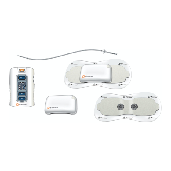
Page 40: Chapter 5: Stimrouter User Kit
StimRouter User Kit Your StimRouter User Kit includes the following: • External Pulse Transmitter (EPT) • Patient Programmer • System Charger Set • Patient Programmer Neck Strap • Patient Programmer Wrist Strap • StimRouter Electrode Carrying Case • User’s Guide •... - Page 41 StimRouter Electrode Carrying Case System Charger Set Wrist Strap Neck Strap User's Guide MP602-00630-001 Rev. E.indd 30 11/15/17 2:21 PM...
-
Page 42: Chapter 6: Device Description
Electrode and Patient Programmer. StimRouter Lead The StimRouter Lead is flexible and approximately 15 cm (6 in.) in length. The lead has a stimulation end and a receiver end. The stimulation end is implanted near or at the targeted peripheral nerve and the receiver end is implanted near the skin surface. The receiver end receives the stimulation signal from the EPT and then sends the signal through the lead to the stimulation end. -
Page 43: Charging Socket And Charging Light
StimRouter Electrode The StimRouter Electrode features: (See Figure 6-4) • Two gel pads that adhere the StimRouter Electrode to the skin. The gel pads also transmit the stimulation signal from the EPT to the receiver end of the lead. • Two snaps for EPT placement. -
Page 44: Stimrouter Electrode Liner
The StimRouter Electrode is disposable and can be reused as long as the gel pads are intact and can fully adhere to the skin or for a maximum of four days of use. The typical lifespan of the StimRouter Electrode is two to four days, depending on: •... -
Page 45: Stimrouter Patient Programmer
Figure 6-6. Inside of the StimRouter Electrode Carrying Case. StimRouter Patient Programmer The StimRouter Patient Programmer communicates wirelessly with the StimRouter EPT. The Patient Programmer is used to: • Turn stimulation on and off. • Adjust stimulation intensity. • Select a stimulation program. -
Page 46: Plus/Minus Buttons
Plus/Minus Buttons The plus and minus buttons are used to increase or decrease stimulation intensity and to select a stimulation program. The minus button is also used to save a preferred stimulation intensity level. Volume Buttons The volume buttons are used to increase, decrease and mute the sound level of the audio alerts. -
Page 47: Stimulation Mode
Stimulation Mode In stimulation mode, the StimRouter components are stimulating the target treatment area. The user can adjust the intensity level of stimulation. Indicator Lights The Patient Programmer has three indicator lights. See Figure 6-8. Patient Programmer Indicator Light On/Off button FLASHES GREEN when the Patient Programmer is ON. -
Page 48: Information Icons
Information Icons The Patient Programmer has three information icons. See Figure 6-8. Patient Programmer Icon • FLASHES YELLOW when the Patient Programmer battery charge level is low. • GLOWS RED to indicate a Patient Programmer error and, when “E” appears in the digital display while charging, a battery charging error. -
Page 49: Program Selection
Program Selection The selected program is displayed as a letter, ranging alphabetically from “A” to “H.” See Figure 6-9. Only programs set by your physician can be selected. Figure 6-9: Stimulation programs A through H, as represented on the Patient Programmer digital display. System Errors If an “E”... -
Page 50: Audio Alerts
Audio Alerts The Patient Programmer emits a variety of audio alerts to signal updates, changes and errors. An audio alert may signal that: • The Patient Programmer has been turned on/off. • A mode has been changed. • A button has been pressed. •... -
Page 51: Connection Port
Your User Kit includes a Patient Programmer neck strap and wrist strap for carrying the Patient Programmer. See Figure 6-12. Wrist Strap Neck Strap Figure 6 -12: StimRouter Patient Programmer accessories. User's Guide MP602-00630-001 Rev. E.indd 40 11/15/17 2:21 PM... -
Page 52: System Charger Set
See Figure 6 -13. Figure 6 -13: System charger set. CAUTION: Use only the charger included in your StimRouter System Kit. Use of any other charger could damage the system. CAUTION: To completely disconnect the power input, the AC/DC adapter portion of the system charger set must be disconnected from the main power supply. - Page 53 User's Guide MP602-00630-001 Rev. E.indd 42 11/15/17 2:21 PM...
-
Page 54: Chapter 7: Set-Up Instructions
Note: Charge the Patient Programmer for at least four hours and the EPT for at least two hours immediately before a programming session. WARNING: Use only the charger included in the StimRouter User Kit. Use of any other charger could result in serious injury. (Refer to Manufacturer Model No. FRIWO FW7555M/05.) - Page 55 The charging process should last approximately one to two hours. Note: It is possible to charge the Patient Programmer and EPT separately, but Bioness recommends that the Patient Programmer and EPT be charged at the same time.
-
Page 56: Preparing The Skin
CAUTION: Skin inflammation in the region of the StimRouter Electrode may be aggravated by pressure from the electrode. If the skin is inflamed or swollen, do not use your StimRouter system until the inflammation is gone. If the skin has a cut or scrape, do not adhere the StimRouter Electrode. -
Page 57: Adhering The Stimrouter Electrode
Figure 7- 2: StimRouter EPT and StimRouter Electrode connecting. Adhering the StimRouter Electrode A StimRouter Electrode can be reused as long as the gel pads are intact and can fully adhere to the skin or for a maximum of four days of use. - Page 58 The center of the gel pad should be above the receiver end of the lead. See Figure 7-5. If the StimRouter Electrode is not directly over the receiver end of the lead, then stimulation may be uncomfortable or ineffective.
- Page 59 Note: The effectiveness of the stimulation is sensitive to the alignment and rotation of the StimRouter Electrode in relation to the receiver end of the lead. If the alignment or rotation of the StimRouter Electrode changes, the stimulation intensity may need to be adjusted.
-
Page 60: Chapter 8: Operating Instructions
• Removing the StimRouter Electrode. • Removing the EPT from the StimRouter Electrode. Before you operate your StimRouter system, be sure to read the previous sections of this guide. Important safety information and features of your StimRouter components are described. If you have any questions, problems or experience any new symptoms or painful areas, contact your physician for appropriate diagnosis and treatment. -
Page 61: Turning The Patient Programmer On/Off
Turning the Patient Programmer On/Off The Patient Programmer on/off button is located at the top of the Patient Programmer. See Figure 8-1. On/Off Button Mode Button Volume Buttons Digital Display Plus/Minus Buttons Figure 8-1: Patient Programmer operating buttons. To turn on the Patient Programmer: 1. -
Page 62: Adjusting The Volume Of Audio Alerts
Adjusting the Volume of Audio Alerts The volume buttons are located on the side of the Patient Programmer. See Figure 8-1. Each time a button is pressed, the Patient Programmer demonstrates the new sound level for audio alerts. • To increase the sound level, press the up arrow. •... -
Page 63: Turning Stimulation On
Mode Button GLOWS YELLOW Selected Program in Digital Display Figure 8-3: Program mode. 3. Press the plus or minus button to select a different program. The selected program will appear in the digital display. 4. Press the mode button briefly to return to standby mode. The Patient Programmer will sound an audio alert and the mode button light will turn off. -
Page 64: Adjusting Stimulation Intensity
3. After a few minutes, the digital display will disappear to save energy. The Patient Programmer (and stimulation) will still be ON. The on/off button will continue to FLASH GREEN. To have the digital display reappear press one of the volume buttons. -
Page 65: Turning Stimulation Off
Electrode” section in this guide. Removing the StimRouter Electrode Remove the StimRouter Electrode from the skin every three to four hours for 15 minutes to allow the skin under the electrode to breathe. The skin can become irritated from prolonged contact with the gel pads on the StimRouter Electrode. -
Page 66: Removing The Ept From Stimrouter Electrode
4. Store the StimRouter Electrode and EPT in the StimRouter Electrode Carrying Case. Removing the EPT from the StimRouter Electrode Remove the EPT from the StimRouter Electrode when the gel pads can no longer adhere to the skin or after a maximum of four days of use. To remove the EPT: Chapter 8 - Operating Instructions MP602-00630-001 Rev. - Page 67 1. Make sure the StimRouter Electrode liner is on. 2. Hold the EPT with your thumb and index finger and gently pull the StimRouter Electrode away from the EPT to unsnap it. See Figure 8-7 Figure 8-7: Removing the EPT from the StimRouter Electrode.
-
Page 68: Chapter 9: Maintenance And Cleaning
Maintenance and Cleaning CAUTION: Do not attempt to repair any of the components in your StimRouter User Kit. If a component does not work, contact Bioness or your local distributor. Unauthorized repair can void your warranty. Use only StimRouter components with your StimRouter system. - Page 69 To replace the battery: 1. Remove the label on the back of the Patient Programmer. The label covers a small screw. See Figure 9-1. Battery Cover Screw Location of Label Battery Battery Compartment Patient Programmer Figure 9-1: Replacing the patient programmer battery. 2.
-
Page 70: Recharging The Ept Battery
StimRouter Electrode. Dispose of the StimRouter Electrode when any of the following occurs: • The gel pads start to peel off at the edges or detach from the StimRouter Electrode. • The gel pads appear worn or dirty. -
Page 71: Registering A New Component
Registering a New Component The EPT and Patient Programmer must be electronically registered to each other to communicate. The components in your User Kit are already electronically registered to each other. You will need to re-register the components if: • You purchase a replacement component. •... -
Page 72: Cleaning
Repeat the procedure. If the problem persists, reconnect the EPT to the system charger. Cleaning All StimRouter User Kit components may be cleaned with water by carefully wiping them with a damp cloth. Do not use detergents or other cleaning agents, unless otherwise specified below. -
Page 73: Disinfecting
(but not dripping) with 70% isopropyl alcohol (IPA) per the instructions below: Note: Do not attempt to disinfect the StimRouter Electrode. If infection is a concern, discard the StimRouter Electrode and use a new electrode. -
Page 74: Chapter 10: Troubleshooting
Should a technical problem occur that is not covered in this section or cannot be resolved by the suggested solutions in this section, please contact Bioness at 800.211.9136 or your local distributor. Do not attempt to repair your StimRouter components. - Page 75 Patient Programmer off and back • Connect the EPT to the system charger. • Re-register the EPT and Patient Programmer. • Contact Bioness or your local distributor. Table 10-3: Troubleshooting, Patient Programmer, RF icon. User's Guide MP602-00630-001 Rev. E.indd 64...
- Page 76 Intensity Level FLASHES in the Digital Display • Make sure that nothing is on the gel pads on the back of the StimRouter Electrode or on the skin that would interfere with electrode contact with the skin. • Re-adhere the StimRouter Electrode to the skin.
- Page 77 • Review the skin care instructions. Clean the skin with a damp cloth. • Change the StimRouter Electrode, if the skin is dry. • Trim hair from the StimRouter Electrode site. • Contact Bioness or your local distributor.
-
Page 78: Chapter 11: Technical Specifications
Technical Specifications Patient Programmer Charger Specifications Use medical Class II safety approved power supply provided/approved by Bioness Inc with the following ratings: Manufacturer’s Model No. FRIWO FW7555M/05 Input Voltage 100-240 volts AC Current 400 milliamperes Frequency 50-60 hertz Output Voltage 5 volts ±... - Page 79 Total Time 10 minutes - 12 hours Conformity Certification The StimRouter complies with Part 15 of the FCC rules. Operation is subject to the following two conditions: 1. This device may not cause harmful interference, and 2. This device must accept any interference received, including interference that may cause undesired operation.
- Page 80 Minus button is used to save new default settings. Volume: Used to increase or decrease sound level of audio alerts. LEDs EPT Icon: Communicates StimRouter electrode and EPT status. Radio Frequency Icon: Communicates patient programmer and EPT registration status. Patient Programmer Icon: Communicates patient programmer status.
- Page 81 FCC ID # TVF-STRP-PP-V00 Conformity Certification The StimRouter complies with Part 15 of the FCC rules. Operation is subject to the following two conditions: 1. This device may not cause harmful interference, and 2. This device must accept any interference received, including interference that may cause undesired operation.
- Page 82 Wireless (RF) Communications Specifications Communication between the patient programmer Capabilities and EPT. RF communication is used between the EPT and patient programmer to perform the following functions: • Control stimulation (e.g., start/stop stimulation, Functions change programs, adjust stimulation amplitude) • EPT status (e.g., low battery indication, status and error messages) Use mode (patient programmer controls EPT Modes...
- Page 83 • Packet error rate of <1% Privacy of StimRouter Wireless Communication While the frequency band used by the StimRouter wireless system can be used by other users of the band, the privacy of the StimRouter wireless system is ensured by: •...
-
Page 84: Chapter 12: Appendix - Emi Tables
(EMC) in accordance with International Electrotechnical Committee (IEC) 60601-1-2. The following tables provide information regarding the EMC testing and guidance for safe use of the system. The StimRouter system should be configured and used in accordance with the instructions provided in this manual. - Page 85 Guidance and Manufacturer’s Declaration Electromagnetic Emissions The StimRouter system is intended for use in the electromagnetic environment specified below. The customer or the user of the StimRouter system should assure that it is used in such an environment. Emissions Test...
- Page 86 Guidance and Manufacturer’s Declaration Electromagnetic Immunity The StimRouter system is intended for use in the electromagnetic environment specified below. The user of the StimRouter system should assure that it is used in such an environment. IEC 60601 Test Electromagnetic Immunity Test...
- Page 87 Guidance and Manufacturer’s Declaration Electromagnetic Immunity The StimRouter system is intended for use in the electromagnetic environment specified below. The customer or the user of the StimRouter system should assure that it is used in such an environment. IEC 60601 Test...
- Page 88 To assess the electromagnetic environment due to fixed RF transmitters, an electromagnetic site survey should be considered. If the measured field strength in the location in which the StimRouter system is used exceeds the applicable RF compliance level above, the StimRouter system should be observed to verify normal operation.
- Page 89 For transmitters rated at a maximum output power not listed above, the recommended separation distance (d) in meters (m) can be estimated using the equation applicable to the frequency of the transmitter, where P is the maximum output power rating of the transmitter in watts (W) according to the transmitter manufacturer.
- Page 90 MP602-00630-001 Rev. E.indd 79 11/15/17 2:21 PM...
Need help?
Do you have a question about the StimRouter and is the answer not in the manual?
Questions and answers