Bioness StimRouter User Manual
Implantable neurostimulator
Hide thumbs
Also See for StimRouter:
- Clinicians manual (108 pages) ,
- Clinician manual (107 pages) ,
- User manual (90 pages)
Table of Contents
Advertisement
Quick Links
Download this manual
See also:
User Manual
Advertisement
Table of Contents

Subscribe to Our Youtube Channel
Related Manuals for Bioness StimRouter


Summary of Contents for Bioness StimRouter
- Page 1 User Manual StimRouter™ Implantable Neurostimulator Bioness Inc. Rx Only United States federal law restricts this device CAUTION: to sale by or on the order of a physician.
- Page 2 Disclaimer Bioness Inc. shall not be liable for any injury or damage suffered by any person, either directly or indirectly, as a result of the unauthorized use or repair of Bioness Inc.
- Page 3 Date of Manufacture Warning Conformity Certification The StimRouter complies with Part 15 of the FCC Rules. Operation is subject to the following two conditions: This device may not cause harmful interference, and This device must accept any interference received, including interference...
-
Page 5: Table Of Contents
Adverse Effects ....8 Your StimRouter User Kit ... 1 Risks Related to Stimulation ..9 Your Programming Session . - Page 6 7. Set-Up Instructions Digital Display... . . 17 Intensity ....17 Charging the Remote Control..27 Program .
- Page 7 Temperature Error ..48 Component Malfunction ... 48 Radio Communication Failure ..49...
-
Page 9: Introduction
Congratulations! Your physician has prescribed the StimRouter Implantable Neurostimulator to help manage your pain. The first step is to have the StimRouter lead implanted where neurostimulation will give you the most pain relief. After the lead is implanted and the skin above the implant site is healed, you can start your stimulation treatment. -
Page 10: User Registration Information
StimRouter products and to activate your StimRouter warranty. Fill out the registration card and return it to Bioness Inc. by mail or by fax as soon as possible. Your Medical Device ID Card Bioness will send you a Medical Device Identification (ID) Card once we receive your registration information. -
Page 11: General Warnings And Cautions
Contraindications The StimRouter should not be used if you have any of the following: An implanted cardiac pacemaker or defibrillator •... -
Page 12: Warnings
StimRouter Implantable Neurostimulator. The energy generated by diathermy can be transferred through the StimRouter, causing tissue damage at the lead site and resulting in severe injury or death. Diathermy may also damage the neurostimulation components, resulting in loss of therapy and requiring additional surgery for lead replacement. -
Page 13: Flammable Fuel Or Chemicals
Flammable Fuel or Chemicals Turn the StimRouter (remote control and stimulation) off when near a refueling point, flammable fuel, fumes or chemicals. The operation of the StimRouter could cause the chemicals or fumes to ignite, causing severe burns, injury or death. -
Page 14: System Programming
Do not adhere the user patch to any other person or to any other part of your body. The StimRouter user patch is meant to be worn only by the patient for which it was prescribed and in the location where it was prescribed. -
Page 15: Keep Out Of Reach Of Children
Persistent redness, lesions or blisters are signs of irritation. Use of the StimRouter should be temporarily halted until the inflammation is resolved. In some cases, irritation can be avoided by changing the stimulation parameters. -
Page 16: X-Ray Examinations
X-Ray Examinations Do not wear the StimRouter user patch during x-ray examinations. Known or Suspected Heart Problems Consult your physician if you have or suspect you have a heart condition. Physicians should use caution when treating patients with suspected or diagnosed heart problems. -
Page 17: Risks Related To Stimulation
Risks Related to Stimulation Operation of the StimRouter may cause increased pain in an area(s) • other than the implant site. The pain may be caused by stimulation of the tissue surrounding the lead (skin, fascia and muscle). You may feel undesirable or unpleasant sensations related to •... - Page 18 2-10 User Manual StimRouter...
-
Page 19: User Kit Contents
• User Instruction Card • User Registration Card • Warranty Card • Check to make sure that all of the above components are included in your User Kit. If anything is missing, call Bioness Customer Support. User Kit Contents 3-11... - Page 20 3-12 User Manual StimRouter...
-
Page 21: Device Description
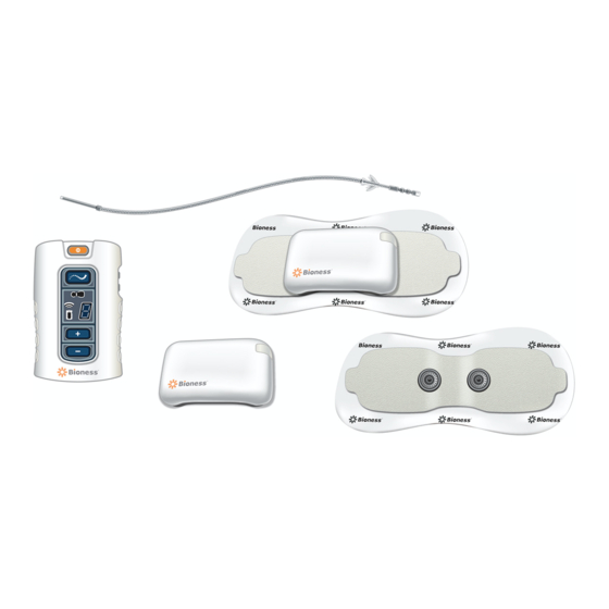
H A P T E R EVICE ESCRIPTION HAPTER Your StimRouter system consists of four key components: An implantable lead • An external user patch • An external pulse transmitter (EPT) • A portable remote control FIGURE 4-1. • FIGURE 4-1. Your StimRouter system components. -
Page 22: Implantable Lead
Implantable Lead The StimRouter lead is about 6 inches long. It has a stimulation end and a pick-up end. The entire lead is implanted. Stimulation End Stimulates the treatment area. Pick-Up End Receives (picks up) the stimulation signal from the external pulse transmitter and sends it to the stimulation end. -
Page 23: Accessories
Designed to help secure the user patch to the skin. External Pulse Transmitter The StimRouter external pulse transmitter (EPT) sends pain-relieving electrical stimulation to the implanted lead. The external pulse transmitter fits into the user patch and responds to wireless commands from the remote control. -
Page 24: Program
In program mode, the available stimulation programs are accessible. To choose a stimulation program, use the plus/minus buttons. Stimulation In stimulation mode, the StimRouter system is on; it is stimulating the target treatment area. Stimulation intensity can be fine-tuned using the plus/minus buttons. -
Page 25: Volume
Volume Used to increase or decrease sound level of the audio indicators. On/Off Indicator Lights Remote Control On/Off button flashes green when the remote control is on. Stimulation Mode button flashes yellow when stimulation mode is on. Program Mode button glows yellow when program mode is on. Digital Display Shows stimulation intensity in stimulation mode, program selected in program mode, charging status, radio frequency registration status and... -
Page 26: Radio Frequency Registration Error
FIGURE 4-3. StimRouter remote control digital display and LEDs. Radio Frequency User Patch Icon (RF) Icon Digital Display Remote Control Icon Radio Frequency Registration Error “E” appears in the digital display. Radio Frequency Registration Complete “C” appears in the digital display. -
Page 27: Remote Control Icon
Remote Control Icon • Flashes yellow: low battery • Glows red: component malfunction or battery charging error Visual Alerts Low Battery, Remote Control Remote control icon flashes yellow • Low Battery, User Patch User patch icon flashes yellow • Faulty Electrode Contact User patch icon flashes red •... -
Page 28: Battery Compartment
Remote Control Wrist Strap Loops through the top of the remote control and is used to carry the remote control. Remote Control Pouch Features a clamp for attachment to a belt and is used to carry the remote control. 4-20 User Manual StimRouter... -
Page 29: Technical Specifications
15°C to 40°C (59°F to 104°F) Charging Temperature 5°C to 40°C (41°F to 104°F) Relative Humidity 25% to 85% Atmospheric Pressure 0.9 kPA to 1.060 kPA Specifications, StimRouter External Pulse Transmitter Classification Externally powered, continuous operation, Type BF applied parts Operating Voltage Technical Specifications 5-21... - Page 30 Specifications, StimRouter External Pulse Transmitter Dimensions Height 9 mm (0.354 in.) Width 35 mm (1.377 in.) Depth 38 mm (1.496 in.) Weight 10 grams (0.352 oz.) Environmental Ranges Transport and Storage Temperature -20°C to 60°C (-4°F to 140°F) Operational Conditions Temperature 5°C to 40°C (41°F to 104°F)
- Page 31 5°C to 40°C (41°F to 104°F) Relative Humidity 25% to 85% Atmospheric Pressure 0.9 kPA to 1.060 kPA Specifications, Remote Control Power Supply Use medical Class II safety approved power supply provided/approved by Bioness Inc. with the following ratings: Input Voltage 100–240 V AC Current...
- Page 32 Specifications, Wireless Link Frequency Band 2.4 GHz, ISM band Transmission Power Complies with FCC 15.247 (for U.S.) 5-24 User Manual StimRouter...
-
Page 33: Environmental Conditions That Affect Use
Do not store your StimRouter components in a car or elsewhere where hot or cold weather temperatures could exceed the acceptable ranges of the components. See Appendix. Temperature extremes can damage the StimRouter components. -
Page 34: Security Screening Devices
The antenna for each transmitter must not be located near to or operating in conjunction with any other antenna or transmitter. Changes or modifications to the StimRouter system not expressly approved by Bioness Inc. could void the user’s authority to operate the equipment. Security Screening Devices... -
Page 35: Set-Up Instructions
A new remote control battery supports at least 24 hours of typical usage before needing to be recharged. The remote control can be operated while it is being charged. Use only the charger included in the StimRouter User Kit. Use of any WARNING: other charger can result in serious injury. -
Page 36: Preparing The Skin
For optimal stimulation, the skin below the user patch should be clean and dry. If the skin is inflamed or swollen, do not use the StimRouter. Inflammation CAUTION: in the region of the user patch may be aggravated by pressure from the user patch. -
Page 37: Operating Instructions
NSTRUCTIONS HAPTER Use only the Bioness components designed and manufactured for the CAUTION: StimRouter. Do not substitute any components for those supplied in the StimRouter User Kit. Overview This section includes the following instructions for performing a StimRouter treatment session: Attaching the External Pulse Transmitter to a User Patch •... -
Page 38: Attaching The Ept To A User Patch
Before operating the StimRouter, read the previous sections of this manual that describe the components and their features. To gain the maximum benefit from your StimRouter, carefully follow your clinician’s instructions. If you have any questions or problems, or experience any new symptoms or painful areas, contact your treating clinician for appropriate diagnosis and treatment. -
Page 39: Turning On The Remote Control
Locate the area where the pick-up electrode is implanted. If necessary, palpate the area until the pick-up electrode can be felt. Clean the skin above the pick-up electrode with an alcohol swab or wet washcloth and then dry the skin area. If the area has been treated with lotions or oils, then clean the skin with soap and water, rinse well and dry. -
Page 40: Adjusting The Volume Of Audio Alerts
FIGURE 8-1. Stimulation programs A–H, as represented on the digital display. The remote control can store up to eight clinician-set stimulation programs. These programs are labeled “A–H” and can be selected using the plus/minus buttons in program mode. See FIGURE 8-1. 8-32 User Manual StimRouter... -
Page 41: Turning Stimulation On
To select a stimulation program: From standby mode, press and hold the mode button for at least three seconds, until the remote control beeps and the mode button glows yellow. A letter will appear in the digital display, indicating the active program. Press the plus or minus button to change the active program. -
Page 42: Saving A New Default Stimulation Intensity Level
From standby mode, press and hold the minus button for at least three seconds. The remote control will beep and the new default intensity level will flash on the digital display for a few seconds while saving. 8-34 User Manual StimRouter... -
Page 43: Turning Stimulation Off
If the remote control malfunctions, or an unexpected response or stimulation level is experienced, take the user patch off and contact Bioness Customer Support. Operating Instructions 8-35... -
Page 44: Taking Off The User Patch
Gently pull the latching mechanism on the user patch back and away from the EPT. Lift out the EPT. Note: Do not dispose of the EPT. Store the EPT in the User Kit or the user patch carrying case, or attach it to a new user patch. 8-36 User Manual StimRouter... - Page 45 Operating Instructions 8-37...
- Page 46 8-38 User Manual StimRouter...
-
Page 47: Maintenance And Cleaning
H A P T E R AINTENANCE AND LEANING HAPTER Do not attempt to repair any of the components supplied in the StimRouter CAUTION: User Kit. If a component malfunctions or is lost, contact Bioness Customer Support. Recharging the Remote Control Battery The remote control battery should be charged daily, after extended storage and when the remote control icon flashes yellow. -
Page 48: Registering A New Component
Battery Cover Screw Battery Remote Control Registering a New Component When you replace your remote control or external pulse transmitter, the new working components must be electronically registered to each other for your StimRouter to operate. 9-40 User Manual StimRouter... - Page 49 To perform the registration procedure, both the remote control and the external pulse transmitter must be operational. Make sure the remote control is charged and that the external pulse transmitter is attached to a user patch with a working battery. Note: Please read all of the instructions below before beginning the registration procedure.
-
Page 50: Replacing The User Patch
If the error indication continues to appear, contact Bioness Customer Support. Replacing the User Patch The user patch is disposable; when the battery loses its charge or the gel... -
Page 51: Cleaning The Components
Note: To ensure proper electrical stimulation, the external pulse transmitter must be connected to the user patch properly. Cleaning the Components All StimRouter components may be cleaned by carefully wiping • with a damp cloth. StimRouter electronic components are not waterproof; do not •... - Page 52 9-44 User Manual StimRouter...
-
Page 53: Troubleshooting
H A P T E R ROUBLESHOOTING HAPTER Should a technical problem occur that is not covered in this section, contact Bioness Customer Support: Telephone: (800) 211-9136. Note: Do not attempt to repair any of your StimRouter components. User Patch Faulty Electrode Contact Indicators Beep •... -
Page 54: Battery Low Charge
Check to see that the external pulse transmitter is snugly attached to the user patch. Re-adhere the user patch to the skin. If the problem persists, adhere a new user patch. If the problem persists, contact Bioness Customer Support. Battery Low Charge Indicators Beep •... -
Page 55: Remote Control
Remote Control Battery Low Charge Indicators Beep • Remote control icon flashes yellow • Corrective Actions Charge the remote control battery. If the problem persists, replace the battery. Battery Failure Indicator When the remote control is turned on, none of the icons lights up; no •... -
Page 56: Battery Charging Error
Corrective Actions Reconnect the charger cable to the remote control. If the problem persists, replace the battery in the remote control. If the problem persists, contact Bioness Customer Support. External Pulse Transmitter Temperature Error Indicator The user patch icon flashes red and “E”... - Page 57 Replace the user patch: use a new user patch and connect the external pulse transmitter to the new patch. If the problem persists, reregister the components. If the problem still persists, contact Bioness Customer Support. Troubleshooting 10-49...
- Page 58 10-50 User Manual StimRouter...
- Page 59 Index mute airports antitheft devices patient ID card battery discharges rapidly battery loses its charge rain or snow rechargeable AAA battery Registration Connected charger cable connector Registration Error charging socket Registration in Progress clinician-set stimulation programs remote control and user patch icons start flash- condensation 48, 49 ing red in succession...
Need help?
Do you have a question about the StimRouter and is the answer not in the manual?
Questions and answers