
Related Manuals for Badger Meter Recordall Compound Series


Summary of Contents for Badger Meter Recordall Compound Series
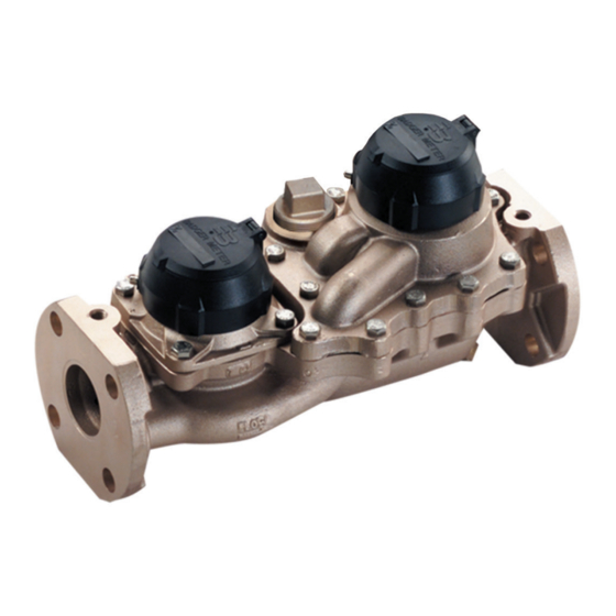
- Page 1 Recordall® Compound Series Meter Lead-Free Bronze Alloy, Sizes 2", 3", 4" & 6" NSF/ANSI Standards 61 and 372 Certified User Manual RCS-UM-00076-EN-04 (June 2016)
- Page 2 Recordall® Compound Series Meter, Lead-Free Bronze Alloy, Sizes 2", 3", 4" & 6" Page ii RCS-UM-00076-EN-04 June 2016...
-
Page 3: Table Of Contents
User Manual CONTENTS Scope of This Manual Product Information Product Description Related Literature Safety Information Unpacking and Inspection Installation Preinstallation Considerations Installing the Meter Adapter Spacers Performance Checks Reading the Recordall Registers (and Encoder) Maintenance Accuracy Testing Maintenance Equipment Preventive Maintenance Periodic Inspection Cleaning Servicing Parts and Assemblies... - Page 4 Recordall® Compound Series Meter, Lead-Free Bronze Alloy, Sizes 2", 3", 4" & 6" Page iv RCS-UM-00076-EN-04 June 2016...
-
Page 5: Scope Of This Manual
The Recordall Compound Series Meters Parts List contains part numbers, part descriptions and illustrations Safety Information The installation of the Recordall Compound Series meter must comply with all applicable federal, state, and local rules, regulations, and codes Failure to read and follow these instructions can lead to misapplication or misuse of the meter, resulting in personal injury and... -
Page 6: Installation
◊ When installing the meter with a Badger Meter Plate Strainer, a minimum of 5 pipe diameters of straight, unobstructed pipe is required upstream of the meter (A minimum of 10 pipe diameters of straight unobstructed pipe is required... -
Page 7: Installing The Meter
Installing the Meter Overall dimensions and laying lengths of each meter size are listed in the Recordall Compound Series Meter Product Data Sheet Review the dimensional requirements, choose an installation point in the piping, and proceed as follows:... -
Page 8: Adapter Spacers
Installation Adapter Spacers The 2" and 4" Compound Series meters are supplied in 15-1/4" and 20" lay lengths respectively If you have an existing compound meter with a lay length of 17" for the 2" size or 24" for the 4" size, a Flange Adapter Kit is available for each to accommodate the difference Mount the Flange Adapter to the outlet side of the meter Figure 2: 2"... -
Page 9: Performance Checks
Installation Performance Checks Any valves or devices controlling the flow of water through a compound meter must always be opened and closed SLOWLY to prevent shock loads that may damage the meter’s rotor assembly Complete the following checks to ensure that a compound meter is properly installed and operational: •... -
Page 10: Maintenance
ALLOWING HIGHER READINGS ON THE LOW FLOW ODOMETER ONLY. Maintenance Equipment The tools and equipment recommended for use in servicing and maintaining of Recordall Compound Series meters consist of the usual complement of hand tools used by plumbers and mechanics... -
Page 11: Periodic Inspection
Maintenance Periodic Inspection • Visually inspect the meter for missing hardware, loose screws, broken or scratched register lenses or any other signs of wear or deterioration • Verify that the meter is operating at the proper flow rate and pressure A loss in pressure, coupled with a decrease in flow rate, may indicate that the screen in the upstream pipeline—or the meter itself—is clogged with foreign material and needs cleaning Cleaning... -
Page 12: Servicing Parts And Assemblies
When the performance of a compound meter indicates a need for servicing, refer to the following instructions pertaining to removal, inspection and installation of service parts and assemblies Also see the Recordall Compound Series Meter Parts List for part numbers of replaceable components and correct ordering information If satisfactory repair cannot be made, contact... - Page 13 Servicing Parts and Assemblies 6" Calibration shaft seal plug O-ring Calibration shaft lock screw Cover plate Calibration shaft Hold down strap Head O-ring Transmission shaft gear Magnet carrier Protection tube Cage insert Calibration linkage Nose cone setscrew Nose cone setscrew Nose cone/straightening vane assembly (2) Transmission shaft...
-
Page 14: Removing The Turbo Measuring Element Assembly From The Cover Plate
Servicing Parts and Assemblies Removing the Turbo Measuring Element Assembly from the Cover Plate 1 Remove the O-ring and cage seal 2 Check for damage and clean or replace prior to reassembly 3 To remove the measuring element from the cover, remove the calibration shaft seal plug and the lock screw 4 Place the cover register-side down on a table or flat surface 5 Lightly tap or press the calibration shaft from the wet side out of the bore in the cover (2", 3"... - Page 15 Servicing Parts and Assemblies 3 If a leak exists at this point in the disassembly of the meter, remove the calibration shaft O-ring Before reinserting the O-ring, apply a light coat of silicon grease to it 4 Clean all parts To gain access to the calibration ring, the straightening vane/nose cone must be removed See “Removing the Magnet Carrier/Top Gear Set”...
-
Page 16: Inspecting The Rotor And Bearings
Servicing Parts and Assemblies Inspecting the Rotor and Bearings To inspect the rotor, remove the nose cone assembly from the measuring element insert as described in "Removing the Magnet Carrier/Top Gear Set" on page 14 Check the rotor worm and blades for signs of damage and wear Also inspect the bearing bushings in the front and rear shaft If damage or wear has occurred, replace the part (see Figure 12) If water deposits are found, remove any mineral deposits... -
Page 17: Removing The Rear Nose Cone
Servicing Parts and Assemblies 6 Press the nose cone assembly fully into the cage insert and turn it counter-clockwise, catching the calibration linkage in the slot 7 Check to see that the rotor spins freely If it does not, remove the nose cone assembly and repeat the procedure 8 Install and tighten the nose cone assembly setscrew 9 Holding the cover plate in one hand, align the thermoplastic cage bayonet-like tabs with the slots in the cover plate (2", 3"... -
Page 18: Removing The Low Flow Side
Servicing Parts and Assemblies Removing the Low Flow Side A typical installation would be equipped with drain and piping valves To inspect or replace components of the Low Flow side, close the upstream and downstream valves However, if the installation does not have a drain valve, proceed as follows to relieve pressure See Figure 8 on page 12 UPSTREAM AND DOWNSTREAM VALVES MUST BE CLOSED BEFORE ATTEMPTING TO REMOVE METER HEAD FROM... -
Page 19: Servicing The Chamber And Disc
Servicing Parts and Assemblies Servicing the Chamber and Disc 1 Remove the screws holding the bottom plate on the cover assembly 2 Remove the bottom plate 3 Remove the chamber retaining strap 4 Lift out the chamber and disc assembly 5 Inspect the chamber and parts (see Figure 9) for visible signs of wear The thrust roller and dovetail insert should be... -
Page 20: Reinstalling The Cover Assembly
The Americas | Badger Meter | 4545 West Brown Deer Rd | PO Box 245036 | Milwaukee, WI 53224-9536 | 800-876-3837 | 414-355-0400 México | Badger Meter de las Americas, S A de C V | Pedro Luis Ogazón N°32 | Esq Angelina N°24 | Colonia Guadalupe Inn | CP 01050 | México, DF | México | +52-55-5662-0882...
Need help?
Do you have a question about the Recordall Compound Series and is the answer not in the manual?
Questions and answers
What is the multiplier for the 4 inch compound meter
The multiplier for the 4-inch Badger Meter Recordall Compound Series meter is 100.
This answer is automatically generated