
Related Manuals for Badger Meter CORIOLIS RCT1000


Summary of Contents for Badger Meter CORIOLIS RCT1000
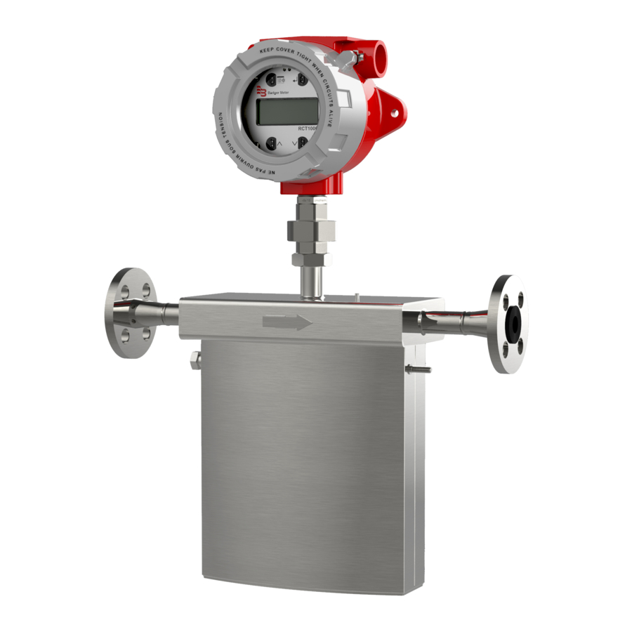
- Page 1 Coriolis Flow Meters RCT1000 with RCS018…300 Sensors for Hazardous Locations Quick Start Guide CRL-QS-01552-EN-05 April 2019...
-
Page 2: Table Of Contents
Coriolis Flow Meters, RCT1000 with RCS018…300 Sensors for Hazardous Locations CONTENTS Purpose of this Document . . . . . . . . . . . . . . . . . . . . . . . . . . . . . . . . . . . . . . . . . . . . . . . . . . . . . . . . . . . . . . . . . 5 Safety . - Page 3 Quick Start Guide Earthing Using Rigid Pipe . . . . . . . . . . . . . . . . . . . . . . . . . . . . . . . . . . . . . . . . . . . . . . . . . . . . . . . . . . . . . 16 EU Earthing Without Rigid Pipe .
- Page 4 Coriolis Flow Meters, RCT1000 with RCS018…300 Sensors for Hazardous Locations Automatic Transmitter Backup . . . . . . . . . . . . . . . . . . . . . . . . . . . . . . . . . . . . . . . . . . . . . . . . . . . . . . . . . . 31 Manual Transmitter Backup .
-
Page 5: Purpose Of This Document
The purpose of this document is to provide you with an overview of the installation, wiring and basic configuration of the Coriolis RCT1000 flow meter . For detailed information, see the "Coriolis Flow Meters User Manual" and the "Coriolis RCTX Control Drawing", both of which can be found on the USB memory stick included with the meter or downloaded from... -
Page 6: Product Label
Product Label PRODUCT LABEL Hazardous Location Remote Sensor Integral Sensor and Transmitter Sensors with integral mount transmitters have a single tag on the sensor . The specific certifications listed on the tag depend on the sensor part number . Certi cations Compatible Transmitter Certi cations... -
Page 7: Dimensions
Dimensions DIMENSIONS RCS018…RCS300 Sensor Dimensions End Fitting (See NOTE) Figure 4: Large sensor dimensions Nominal Sensor E (Standard) 4 E (Remote) Size RCS018 1/2 in . 19 .3 in . (489 mm) 18 .3 in . (464 mm) 13 .6 in . (346 mm 7 .1 in . -
Page 8: Rctx Remote Mount Electronics Enclosure Dimensions
Dimensions RCTX Remote Mount Electronics Enclosure Dimensions 2×Ø 0.31 in. (7.8 mm) Figure 5: RCTX remote mount dimensions 6 .57 in . (167 mm) 5 .20 in . (132 mm) 13 .43 in . (341 mm) 5 .85 in . (148 .7 mm) 4 .57 in . -
Page 9: Installation Overview
Installation Overview INSTALLATION OVERVIEW In general, the following steps are required to install and put the meter into service . 1 . Unpack meter components and transport to the installation location . 2 . Install the transmitter and sensor . 3 . -
Page 10: Sensor Installation
Sensor Installation SENSOR INSTALLATION Before installation, configuration or operation, familiarize yourself with the equipment and operating requirements by reading all sections of this manual . Make sure the site has been thoroughly prepared and is suitable for installation . Preinstallation Considerations MPORTANT Remove all process connection caps and make sure process connections are open. -
Page 11: Sensor Mounting Positions And Locations
Sensor Installation Sensor Mounting Positions and Locations • Always mount the sensor downstream of the flow . • Use vibration-reducing pipe supports approximately 3 and 6 pipe diameters from the end of the sensor in all applications . • Install the sensor in a section of the piping where it always remains full, unless the application is designed to drain with no flow . -
Page 12: Horizontal Mounting With Tubes Up
Sensor Installation Horizontal Mounting with Tubes Up The mounting orientation shown in Figure 13 is recommended for gas or slurry applications where condensate may be present . Flow Flow Figure 13: Tubes up (gases and slurries) Supports—Customer supplied Rigid pipe supports approximately 3 and 6 pipe diameters from the end of the sensor Isolation Valves—Customer supplied Full port ball Ground... -
Page 13: Vertical Mounting With Tubes To The Side, Flow Going Up
Sensor Installation Vertical Mounting with Tubes to the Side, Flow Going Up The mounting orientation shown in Figure 16 is recommended for self-draining configurations . Flow Flow Figure 16: Tubes to the side with flow going up (self-draining) Supports—Customer supplied Rigid pipe supports approximately 3 and 6 pipe diameters from the end of the sensor Isolation Valves—Customer supplied Full port ball... -
Page 14: Transmitter Installation
Transmitter Installation TRANSMITTER INSTALLATION For wiring details, see the "Coriolis Flow Meters RCTX Control Drawing" included with this product or download it from www.badgermeter.com . RCTX Transmitters The RCTX transmitter is either integrated into the sensor or mounted remotely from the sensor . Install the transmitter in an area convenient for observing the LCD readout (RCTX with Display ONLY), programming and servicing . -
Page 15: Rctx Transmitters With Integral Mount
Transmitter Installation RCTX Transmitters with Integral Mount Conduit Hole Conduit Hole To rotate the orientation of the transmitter RCTX Transmitter relative to the sensor: 1 . Loosen the 1-3/4 in . union hex nut . Be Wired Feedthrough careful to not loosen the feedthrough to Hex Nut the enclosure . -
Page 16: Locking The Transmitter Cover
Ground/Earth Connection Locking the Transmitter Cover To prevent the cover from loosening due to vibration, tighten the setscrew into the enclosure . See Figure 20 . To lock the cover on the transmitter housing, remove the setscrew and thread a customer-supplied chain or cable through the setscrew hole and the hole on the nearest tab . -
Page 17: Opening The Cover And Removing The Display Board
Opening the Cover and Removing the Display Board OPENING THE COVER AND REMOVING THE DISPLAY BOARD OBSERVE PRECAUTIONS FOR HANDLING ELECTROSTATIC-SENSITIVE DEVICES. 1 . Turn off power to the unit . 2 . Grasp the enclosure cover and turn it counter-clockwise until it separates from the enclosure body . Set the cover aside . 3 . -
Page 18: Dc Power Connections
DC Power Connections DC POWER CONNECTIONS OTEE: Use a small bladed screwdriver to secure wires to the connectors . The RCTX operates from a 18…28V DC Class 2 source, as long as the source is capable of supplying a minimum of 7W . 1 . -
Page 19: Inputs / Outputs
Inputs / Outputs INPUTS / OUTPUTS The transmitter powers the current loop . Applying power from any other external device or load will result in damage to the transmitter . OTEE: The IOut1 (HART Option), IOut2, and IOut3 designations can represent any parameters . Units of measure are (appropriately) different . -
Page 20: Rctx Interface Diagrams
Inputs / Outputs RCTX Interface Diagrams TYPICAL STATUS_IN 1, 2, & 3 INTERFACE RCTX EXTERNAL EQUIPMENT TB100 1.00 K, 1W 5, 6, & 7 V DC 5…28V DC Vf: Typ 1.25V Figure 24: Typical status_in 1, 2 and 3 interface FREQUENCY OUTPUT EXTERNAL EQUIPMENT V DC... -
Page 21: Replacing The Display Board
Inputs / Outputs Replacing the Display Board OBSERVE PRECAUTIONS FOR HANDLING ELECTROSTATIC-SENSITIVE DEVICES. 1 . Turn off power to the unit . 2 . Grasp the enclosure cover and turn it counter-clockwise until it separates from the enclosure body . Set the cover aside . 3 . -
Page 22: Sensor Connections
Sensor Connections SENSOR CONNECTIONS • Integral RCTX transmitters are prewired to the sensor at the factory (no wiring required) . • Remotely mounted RCTX transmitters must be wired to the sensor during installation . OTEE: The black wire with the ring connector terminates at the transmitter . The thicker white wire terminates at the sensor . YEL OR GRY For wiring details, see the “Coriolis Flow Meters... -
Page 23: Transmitter Setup
Transmitter Setup YEL OR GRY Figure 33: Remote RCTX terminal boxes TRANSMITTER SETUP Commissioning of the RCT1000 Coriolis system can be accomplished via the keypad on the transmitter, or through the RCT Console, a free software program included on the USB thumb drive provided with purchase . This software is also available for download at www.badgermeter.com . -
Page 24: Basic Operation
Sensor Connections Basic Operation Using the Keypad The buttons are used individually to execute a command or effect a change, according to the mode of the firmware . Button presses are time sensitive . The firmware recognizes two button press durations known as Press and Long Press . A Press lasts for less than two seconds . -
Page 25: Meter Checks
Sensor Connections Meter Checks 1 . Confirm the flow sensor has been installed correctly . 2 . Confirm the transmitter has been installed correctly . 3 . Confirm all transmitter connections have been made correctly to the sensor . 4 . Confirm the Flow Factor and Density calibration constants are the same on both the serial tags and calibration documents . 5 . -
Page 26: Menu Map
Menu Map MENU MAP MEASUREMENT Parameter List SENSOR Parameter List SYSTEM IO STAT Parameter List ABOUT Parameter List FLOW Parameter List DENSITY Parameter List CALIBRATION TEMPERATURE Parameter List DRIVER Parameter List ZERO CALIBRATION Parameter List PRIMARY Parameter List CURRENT1 SETUP Parameter List SET UP CURRENT2 SETUP... -
Page 27: Keyboard Lock
Keyboard Lock KEYBOARD LOCK The optical buttons on the hazardous location RCTX transmitter may be locked to prevent accidental activation of the buttons . To unlock, press the Up arrow, Down arrow, Menu/Exit and Enter buttons sequentially, in a reverse "Z" pattern . Figure 41 . -
Page 28: Sensor Check
Sensor Check SENSOR CHECK It is important to check that the sensor and transmitter are correctly matched . Unmatched sensor and transmitter pairs will produce inaccurate readings . To check that the correct sensor has been connected to the correct transmitter, refer to the calibration documents that are sent with the meter system . -
Page 29: Home Screen Setup
Home Screen Setup 9 . Press Menu until the top level menu screen is reached . 10 . Use Up or Down to scroll through the list until MEASUREMENT is in the active line, then press Enter . 11 . Use Up or Down to find the mFlo parameter . It should read all zeros . 12 . -
Page 30: H M I Examples
H M I Examples 4 . To enable or disable one of these menus, use Up or Down to scroll through the list and place the required menu to be Enabled or Disabled into the active line of the display . 5 . -
Page 31: Flow Direction
Flow Direction FLOW DIRECTION If the fluid flow is reverse of the meter flow and reading negative flow when positive flow is desired, change the mass flow linearization factor mLinFct from 1 to –1 . Changing this parameter requires the proper security level . 1 . -
Page 32: Output Configuration
Output Configuration OUTPUT CONFIGURATION Current Outputs The RCTX transmitters have two current outputs plus a current output with HART (if the HART option is installed) that can send signals to peripheral devices (such as loop-powered remote indicators, controllers and similar equipment) . These outputs may be independently set by the user, via software or keypad, for any range between 0…22 mA with 4…20 mA being the default . -
Page 33: Frequency, Pulse And Pwm Outputs
Output Configuration Frequency, Pulse and PWM Outputs The frequency channel has three modes . The first is straight frequency output in the range of 63…10,000 Hz with 3000 Hz being the typical maximum . The second is a pulse output (one pulse per every defined mass unit) . The third is a pulse- width modulation (PWM) output that varies the ratio of on time to a set period . -
Page 34: Communication Wiring And Setup
Communication Wiring and Setup COMMUNICATION WIRING AND SETUP All RCT1000 transmitters include EIA-485 and USB programming ports . OTEE: An RS485 Terminator resistor is provided for when end-of-line termination is required . The RCTX and RCTX with Display transmitters are shipped from factory with the shunt jumper in ”Not Terminated” position . EIA-485 Port The EIA-485 port is used for network connections and supports two protocol options: Modbus RTU and BMI Massmeter . -
Page 35: Troubleshooting
Troubleshooting TROUBLESHOOTING Navigation During an Alarm Condition When any sort of warning occurs, the keypad functionality changes—a momentary press of the Menu/Back button brings up the Warnings menu . At this time, you may feel you are stuck in a loop toggling back and forth between the Display and an alarm or warning . -
Page 36: Indicated Error Levels
Troubleshooting When first installed, the meter must be filled and zeroed . Before zeroing, the green LED may indicate a flow rate . After the zero process it should indicate no flow by blinking at the slow rate . Indicated Error Levels Error levels 1 or 2 are high or low limit indications, such as one of the user-settable alarm limits, one of the 4…20 mA limits or frequency output scaling limits is exceeded . -
Page 37: Error Messages
Troubleshooting Error Messages OTEE: Under certain conditions, multiple error/alarm conditions may exist . If alarms keep appearing, identify the message and keep taking corrective action until all messages cease . Alarm Error Message Error Description Possible Faults and Corrections Level Code Error Microprocessor program error, RAM Xram Error... -
Page 38: Troubleshooting Symptoms
Troubleshooting Troubleshooting Symptoms Symptom Possible Cause Recommended Action Confirm power is available to the transmitter . Measure voltage at the power terminals and check that the voltage matches the labels by the power terminals . Check that the power terminal block is firmly seated . For AC power, verify that the 115V/230V switch is in the correct position . - Page 39 Troubleshooting Symptom Possible Cause Recommended Action Check process loop for entrained air and concentration of mix fluids which will impact the density . Run HealthTrack, the advanced function in RCT Console configuration software, to record critical measurements . Multiple, vital parameters can be viewed in a single snapshot to assist with diagnosing issues .
- Page 40 The Americas | Badger Meter | 4545 West Brown Deer Rd | PO Box 245036 | Milwaukee, WI 53224-9536 | 800-876-3837 | 414-355-0400 México | Badger Meter de las Americas, S.A. de C.V. | Pedro Luis Ogazón N°32 | Esq. Angelina N°24 | Colonia Guadalupe Inn | CP 01050 | México, DF | México | +52-55-5662-0882 Europe, Eastern Europe Branch Office (for Poland, Latvia, Lithuania, Estonia, Ukraine, Belarus) | Badger Meter Europe | ul.
Need help?
Do you have a question about the CORIOLIS RCT1000 and is the answer not in the manual?
Questions and answers