
Related Manuals for Badger Meter iSonic 2000


Summary of Contents for Badger Meter iSonic 2000
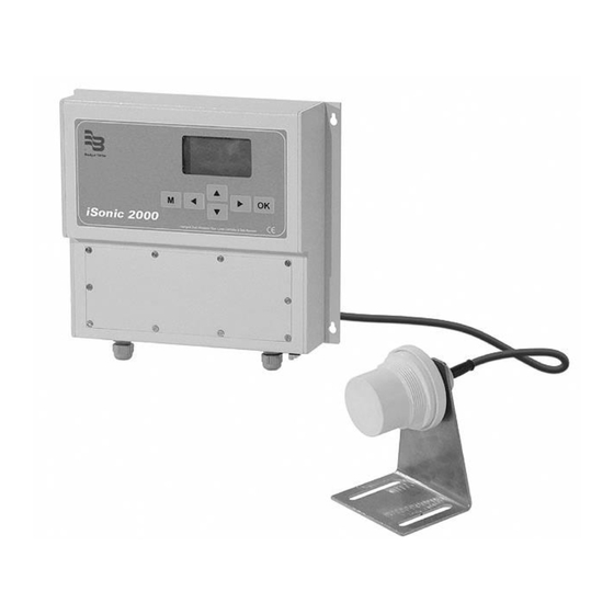
- Page 1 ® Badger Meter Europa GmbH iSonic 2000 Intelligent ultrasonic meter and controller PC Menu system October 2013 (Applicable to iSonic Firmware revision 1.6) UF_iSonic2000_BA_02_1310...
-
Page 2: Table Of Contents
Content 1. Introduction ...................... 1 2. Run screens ...................... 2 3. Main menu......................3 4. Configuration menu ..................4 5. I/O channels: Transducer menu ..............5 6. I/O channels: Process setup menu ..............6 7. I/O channels: Analog inputs ................10 8. -
Page 3: Introduction
Introduction 1 / 24 1. Introduction The user-interface for the iSonic consists of a graphic LCD and a 6-key keyboard. With this interface, the user can configure the entire set-up of the instrument and select different information screens whilst the unit is in measurement mode. After a power-up, the iSonic will always start the measuring process, this is called RUN mode. -
Page 4: Run Screens
Run screens 2 / 24 2. Run screens The first screen that is brought up by the unit combines most of the measurements that are being taken. It typically looks as follows: System Data Logging, Time On or Off TRD1, Temperature &... -
Page 5: Main Menu
Main menu 3 / 24 Relay and Analogue Inputs screen: This screen shows the analogue inputs in mA and in percentage value. It also shows the complete status of each relay, whether it is ON (1) or OFF (0), the ON switch point and the OFF switch point, and what the current process value is. -
Page 6: Configuration Menu
Configuration menu 4 / 24 Once the password is correctly entered, the main menu navigation screen will appear: During menu navigating, a ‘>’ character on the left hand side of the screen will indicate at which menu entry the user is busy. Pressing the Up & Down arrow keys moves the selection indicator. -
Page 7: I/O Channels: Transducer Menu
I/O channels: Transducer menu 5 / 24 The iSonic supports: o Temperature: C°, F° o Level: mm, m, inch, ft o Volume: m , l, acft (Acre Feet), gal(USA), gal(UK), bbl (Barrel) o Flow: m /s, m /d, l/s, cfs, Mgd(USA), gpm(USA), Mgd(UK), gpm(UK) One special note on gallons;... -
Page 8: I/O Channels: Process Setup Menu
I/O channels: Process setup menu 6 / 24 Using this menu, the user can edit all the parameters for Transducer 1: Whether it is active (On / Off) The transducer’s active frequency, settable in kHz Which type of measurement is being performed, this can be Level, Volume, Flow, Function or Sound. - Page 9 I/O channels: Process setup menu 7 / 24 Volume setup Again, the 0% and 100% points can be programmed here, but in addition, the tank can be described as: Vertical Cylinder (“Vert Cyl”) Vertical Cylinder with a Bottom Cone (“V-Cyl +Cone”). The “X Dim:” value is used to describe the height of the cone.
- Page 10 I/O channels: Process setup menu 8 / 24 Alarm setup If an alarm is required for the relevant transducer (‘1’ in this screen), this is where to configure that alarm. Typically, the Alarm indicates an out-of-process value hence the “Alarm above” and “Alarm below” values. The setting is in percentages of the entire measurement range.
- Page 11 I/O channels: Analog inputs 9 / 24 Configuration of sensor distance UF_iSonic2000_BA_02_1310...
-
Page 12: I/O Channels: Analog Inputs
I/O channels: Analog inputs 10 / 24 7. I/O channels: Analog inputs Selecting the A/D inputs under “I/O Channels” presents the user with the following screen: The Analogue inputs can be: Logged only Used as an alarm input ... - Page 13 I/O channels: Relay 11 / 24 “Rotate:”, enters this particular relay into the rotation list. This feature is used for pump control where several pumps need to be operated in an even wear mode. “Timer:”, allows the user to select a number of options: o “Inactive”, the timer is not running o “Daily”, the relay is switched ON at a certain time of the day and switched OFF again at another time.
-
Page 14: I/O Channels: Digital Inputs
I/O channels: Digital inputs 12 / 24 9. I/O channels: Digital inputs Selecting “Digital In” under “I/O Channels” presents the user with: The “Type” tells the iSonic what the usage of this particular input is, it can be either a control input or a pulse output from, say, a water meter. - Page 15 I/O channels: Analog outputs 13 / 24 The 4 and 20mA points can be programmed for any percentage of the process value of the relevant channel. The unit will linearly interpolate the output current between the two set points. If for example the percentages are set for 90% and 10% then for any PV value >90% the unit will maintain 4mA and for any PV value <10% the unit will maintain 20mA.
-
Page 16: Logging, Power And Communications
Logging, power and communications 14 / 24 Meaning that Output 1 and Output 2 are mutually exclusive, if the PID response is in the 100% to 50% domain, then Output 1 is active and Output 2 is 4mA, if the response is in the 50% to 0% domain, then Output 1 is 4mA and Output2 is active. -
Page 17: Calibration
Calibration 15 / 24 Entering the “Port 2” menu, results in: The “Mode” parameter is used to configure the communications mode of iSonic’s second data port. The available selection options are: STALK, use the proprietary protocol TEXT, all measurements are dumped out of the port at 1 second intervals. ... -
Page 18: Tuning
Tuning 16 / 24 It is possible to calibrate: the 4mA to 20mA outputs, once for each current output the internal calibration for measurement of the external thermistors current input calibration of both analogue inputs voltage input calibration of both analogue inputs At any stage, abort of the calibration process can be achieved by pressing the ‘M’... - Page 19 Tuning 17 / 24 The initial settings for this process are as per current configuration and running conditions. Please note that key usage in this section is slightly different from normal, it is no longer necessary to press the ‘OK’ button to enter a value, simply use the Left & Right buttons (◄►) to change values for a selection, the Up and Down buttons (▲▼) work normally.
- Page 20 Tuning 18 / 24 Number 1 can be checked by looking at the ring down slope of the transmission pulse. When zooming to the highest magnification, the ring down slope of the transducer should look somewhat like the following picture: The downward slope is smooth showing that the installation was properly done.
-
Page 21: Language Selection
Language selection / Change password / Special function setup 19 / 24 14. Language selection The language selection is made from the main menu by selecting the “Language” entry. Standard available languages are English, French and Spanish. Other languages will require a re-load of the firmware of the instrument. - Page 22 Language selection / Change password / Special function setup 20 / 24 To make the above-described situations working correctly, please perform the following actions: Select “Function” for Transducer 1’s measurement type. (“Configuration -> I/O channels -> Transducer 1->Type”) Select the required operation under Transducer 1’s function. This can be Add, Subtract or Average.
- Page 23 Language selection / Change password / Special function setup 21 / 24 When selecting custom table for Differential Flow operation, the following section applies: The principle behind this set-up is to measure the levels of both transducers, subtract them (measured level = level TRD1 – level TRD2), and then process the level according to a customised look-up table.
-
Page 24: Total Menu System
Total menu system 22 / 24 17. Total menu system Configure I/O channels Transducer: (2) Active: Freq: 000.00KHz Level Volume Type: Flow Function Sound None - 128 Filter: Deadband: Slow Rate: Medium Fast Process Level setup 100%: Setup Volume setup 100%: Vert Cyl V-Cyl+Cone... - Page 25 Total menu system 23 / 24 Analog In Active: 4-20mA Type: 0-5V Alarm setup Active: Alarm above: 000.0% 000.0% Alarm below: Hysteresis: 000.0% Relay: (4) In use: Trd 1 Trd 2 A/D 1 Channel: A/D 2 NONE On perc: 000.0% Off perc: 000.0% Rotate:...
- Page 26 Total menu system 24 / 24 Log/Power/Comms Data log: Interval(min): Power save: Clear EVENTS Clear DATA log STALK Text Port 2 Mode: Tel- STALK Tel- Text MODBUS Tel- MODBUS 1200 2400 Baud: 4800 9600 Address: 1- 99 Factory default °C Units Temperature: °F...
- Page 28 Hotline Tel. +49-7025-9208-0 or -79 +49-7025-9208-15 Badger Meter Europa GmbH ® Subsidiary of Badger Meter, Inc. Nürtinger Strasse 76 72639 Neuffen (Germany) E-mail: badger@badgermeter.de www.badgermeter.de...
Need help?
Do you have a question about the iSonic 2000 and is the answer not in the manual?
Questions and answers