Table of Contents
Advertisement
Quick Links
www.ti.com
User's Guide
LMK5C33216EVM User's Guide
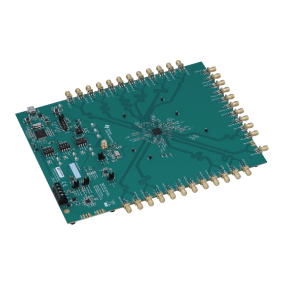
The LMK5C33216EVM is an evaluation module for the LMK5C33216 Network Clock Generator and
Synchronizer. The EVM can be used for device evaluation, compliance testing, and system prototyping.
1
Introduction.............................................................................................................................................................................2
Start......................................................................................................................................................................4
Configuration..................................................................................................................................................................7
3.1 Power Supply.....................................................................................................................................................................
3.2 Logic Inputs and Outputs...................................................................................................................................................
3.3 Switching Between I2C and SPI......................................................................................................................................
3.4 Generating SYSREF Request..........................................................................................................................................
3.5 XO Input...........................................................................................................................................................................
Inputs....................................................................................................................................................13
Outputs...................................................................................................................................................................13
3.8 Status Outputs and LEDS................................................................................................................................................
3.9 Requirements for Making Measurements........................................................................................................................
4 EVM Schematics...................................................................................................................................................................
4.1 Power Supply Schematic.................................................................................................................................................
4.2 Power Distribution Schematic..........................................................................................................................................
4.7 XO Schematic..................................................................................................................................................................
4.8 Logic I/O Interfaces Schematic........................................................................................................................................
Schematic.......................................................................................................................................................22
Materials.............................................................................................................................................................23
5.1 Loop Filter and Vibration Nonsensitive Capacitors..........................................................................................................
6.1 Using the Start Page........................................................................................................................................................
6.2 Using the Status Page.....................................................................................................................................................
Page........................................................................................................................................................31
6.4 Using APLL1, 2, and 3 Pages..........................................................................................................................................
6.6 Using the Validation Page................................................................................................................................................
Page.......................................................................................................................................................37
6.8 Using the Outputs Page...................................................................................................................................................
7 Revision History...................................................................................................................................................................
Trademarks
All trademarks are the property of their respective owners.
SNAU260A - OCTOBER 2020 - REVISED FEBRUARY 2021
Submit Document Feedback
ABSTRACT
Table of Contents
Schematic....................................................................................16
Schematic........................................................................................................................17
Schematic........................................................................................................................18
Schematic....................................................................................................................19
Software..................................................................................................................28
Copyright © 2021 Texas Instruments Incorporated
Table of Contents
LMK5C33216EVM User's Guide
8
9
10
11
11
13
13
14
14
15
20
21
27
28
30
34
36
37
38
1
Advertisement
Table of Contents

Related Manuals for Texas Instruments LMK5C33216EVM


Summary of Contents for Texas Instruments LMK5C33216EVM
-
Page 1: Table Of Contents
Table of Contents User’s Guide LMK5C33216EVM User's Guide ABSTRACT The LMK5C33216EVM is an evaluation module for the LMK5C33216 Network Clock Generator and Synchronizer. The EVM can be used for device evaluation, compliance testing, and system prototyping. Table of Contents Introduction.....................................2 2 EVM Quick Start..................................4... -
Page 2: Introduction
1 Introduction Overview The LMK5C33216EVM is an evaluation module for the LMK5C33216 Network Clock Generator and Synchronizer. The EVM can be used for device evaluation, compliance testing, and system prototyping. The LMK5C33216 integrates three Analog PLLs (APLL) and three Digital PLLs (DPLL) with programmable loop bandwidth. - Page 3 Introduction Figure 1-1. LMK5C33216EVM Default Setting of Jumpers and Dip Switches SNAU260A – OCTOBER 2020 – REVISED FEBRUARY 2021 LMK5C33216EVM User's Guide Submit Document Feedback Copyright © 2021 Texas Instruments Incorporated...
-
Page 4: Evm Quick Start
Click identify to blink LED illustrated in Figure 2-1. This confirms you are connected to the board you expect. LMK5C33216EVM User's Guide SNAU260A – OCTOBER 2020 – REVISED FEBRUARY 2021 Submit Document Feedback Copyright © 2021 Texas Instruments Incorporated... - Page 5 Press Clear Latched Bits button ii. Read Status Bits d. It may take some time for the DPLL status bits to reflect lock. SNAU260A – OCTOBER 2020 – REVISED FEBRUARY 2021 LMK5C33216EVM User's Guide Submit Document Feedback Copyright © 2021 Texas Instruments Incorporated...
- Page 6 EVM Quick Start www.ti.com Figure 2-2. Read Status Bits Measure Measurements may now be made at the clock outputs. LMK5C33216EVM User's Guide SNAU260A – OCTOBER 2020 – REVISED FEBRUARY 2021 Submit Document Feedback Copyright © 2021 Texas Instruments Incorporated...
-
Page 7: Evm Configuration
PDN pin through the GUI Jumper Header for I C/SPI interface (MCU to DUT) SCL or SCK busy indication LED. USB Port for MCU SNAU260A – OCTOBER 2020 – REVISED FEBRUARY 2021 LMK5C33216EVM User's Guide Submit Document Feedback Copyright © 2021 Texas Instruments Incorporated... -
Page 8: Power Supply
VDDO rails of the DUT and its peripheral circuitry. A separate LDO regulator (U4),also supplied from VIN1, is used to power the onboard XO circuits. LMK5C33216EVM User's Guide SNAU260A – OCTOBER 2020 – REVISED FEBRUARY 2021 Submit Document Feedback Copyright © 2021 Texas Instruments Incorporated... -
Page 9: Logic Inputs And Outputs
The logic I/O pins of the DUT support different functions depending on the device start-up mode chosen by the GPIO1 input level upon POR. SNAU260A – OCTOBER 2020 – REVISED FEBRUARY 2021 LMK5C33216EVM User's Guide Submit Document Feedback Copyright © 2021 Texas Instruments Incorporated... -
Page 10: Switching Between I2C And Spi
In SPI mode, GPIO2 must also be configured as STATUS or INT and SPI Readback Data (SDO) to support SPI readback. Figure 3-5. GPIO2 Setting for SPI Mode LMK5C33216EVM User's Guide SNAU260A – OCTOBER 2020 – REVISED FEBRUARY 2021 Submit Document Feedback Copyright © 2021 Texas Instruments Incorporated... -
Page 11: Generating Sysref Request
APLLs which utilize XO input as their reference. For APLL only mode (DPLL not used), the XO SNAU260A – OCTOBER 2020 – REVISED FEBRUARY 2021 LMK5C33216EVM User's Guide Submit Document Feedback Copyright © 2021 Texas Instruments Incorporated... - Page 12 DUT with the onboard termination and AC coupling. See Figure 3-10. Y1 can be used to evaluate various frequency configurations. LMK5C33216EVM User's Guide SNAU260A – OCTOBER 2020 – REVISED FEBRUARY 2021 Submit Document Feedback Copyright © 2021 Texas Instruments Incorporated...
-
Page 13: Reference Clock Inputs
(3.3-V LVCMOS or NMOS open-drain). 3.9 Requirements for Making Measurements When performing measurements with the LMK5C33216EVM, the following procedures must be completed: 1. Ensure all required outputs have proper termination components installed to match the desired output types. -
Page 14: Evm Schematics
LDO3 SNT-100-BK-G M20-8770342 30.9k 0.47uF FB/SNS 10uF 0.01uF 10uF 10.0k 0.47uF VIN2 VIN2 47µF DIODE_SCHOTTKY VIN2 Figure 4-1. Power Supplies LMK5C33216EVM User's Guide SNAU260A – OCTOBER 2020 – REVISED FEBRUARY 2021 Submit Document Feedback Copyright © 2021 Texas Instruments Incorporated... -
Page 15: Power Distribution Schematic
VDD_APLL3 VDD_APLL3 0.1uF 10uF 0.1uF GND TEST POINTS TP19 TP20 TP21 TP22 TP23 TP24 TP25 TP26 Figure 4-2. Power Distribution SNAU260A – OCTOBER 2020 – REVISED FEBRUARY 2021 LMK5C33216EVM User's Guide Submit Document Feedback Copyright © 2021 Texas Instruments Incorporated... -
Page 16: Lmk5C33216 And Input Reference Inputs In0 To In1 Schematic
142-0701-201 ClassName: XO_trace 100nF 0.047µF 0.1µF TP29 470nF 0.047µF 0.1µF Figure 4-3. LMK5C33216 and Input Reference Inputs IN0 to IN1 LMK5C33216EVM User's Guide SNAU260A – OCTOBER 2020 – REVISED FEBRUARY 2021 Submit Document Feedback Copyright © 2021 Texas Instruments Incorporated... -
Page 17: Clock Outputs Out0 To Out3 Schematic
49.9 0.1uF 49.9 ClassName: OUT_LenMatch1a ClassName: OUT_LenMatch1b OUT2_N ClassName: OUT_LenMatch1a ClassName: OUT_LenMatch1b OUT3_N Figure 4-4. Clock Outputs OUT0 to OUT3 SNAU260A – OCTOBER 2020 – REVISED FEBRUARY 2021 LMK5C33216EVM User's Guide Submit Document Feedback Copyright © 2021 Texas Instruments Incorporated... -
Page 18: Clock Outputs Out4 To Out9 Schematic
SMA_O8_N OUT9_N SMA_O9_N R116 R117 R118 R119 0.1uF 0.1uF 49.9 49.9 OUT8_N OUT9_N Figure 4-5. Clock Outputs OUT4 to OUT9 LMK5C33216EVM User's Guide SNAU260A – OCTOBER 2020 – REVISED FEBRUARY 2021 Submit Document Feedback Copyright © 2021 Texas Instruments Incorporated... -
Page 19: Clock Outputs Out10 To Out15 Schematic
ClassName: OUT_LenMatch2a ClassName: OUT_LenMatch2b 0.1uF R142 OUT14_N R143 49.9 ClassName: OUT_LenMatch2a ClassName: OUT_LenMatch2b OUT15_N Figure 4-6. Clock Outputs OUT10 to OUT15 SNAU260A – OCTOBER 2020 – REVISED FEBRUARY 2021 LMK5C33216EVM User's Guide Submit Document Feedback Copyright © 2021 Texas Instruments Incorporated... -
Page 20: Xo Schematic
Output OUTPUT Control_Voltage(Vc) 0.1uF ROM9070PA ClassName: XO_trace ClassName: XO_trace ROX2522S4 VCC_XO_FILT CLK+ CLK- EN_XO CDC64XX-2520 ClassName: XO_trace Figure 4-7. XO LMK5C33216EVM User's Guide SNAU260A – OCTOBER 2020 – REVISED FEBRUARY 2021 Submit Document Feedback Copyright © 2021 Texas Instruments Incorporated... -
Page 21: Logic I/O Interfaces Schematic
Active High LED Yellow BSS138 2.5 mA VDDGPIO TP40 PDN_R LMKPDN U2AGPIO3 0.1uF 1.0k S5 PDN Figure 4-8. Logic I/O Interfaces SNAU260A – OCTOBER 2020 – REVISED FEBRUARY 2021 LMK5C33216EVM User's Guide Submit Document Feedback Copyright © 2021 Texas Instruments Incorporated... -
Page 22: Usb2Any Schematic
VUSB VSSU BSS138 AVSS1 AVCC1 AVSS2 DVCC1 DVSS1 DVCC2 DVSS2 C142 C143 C144 0.1uF 0.1uF 0.1uF Figure 4-9. USB MCU LMK5C33216EVM User's Guide SNAU260A – OCTOBER 2020 – REVISED FEBRUARY 2021 Submit Document Feedback Copyright © 2021 Texas Instruments Incorporated... -
Page 23: Evm Bill Of Materials
Diode, Schottky, 30 V, 0.2 A, SOT-23 BAT54-7-F Diodes Inc. 7.5V Diode, Zener, 7.5 V, 550 mW, SMB 1SMB5922BT3G ON Semiconductor SNAU260A – OCTOBER 2020 – REVISED FEBRUARY 2021 LMK5C33216EVM User's Guide Submit Document Feedback Copyright © 2021 Texas Instruments Incorporated... - Page 24 R157, R158, R163, R164 R13, R14, R15, R54, RES, 470, 5%, 0.1 W, AEC-Q200 Grade 0, CRCW0603470RJNEA Vishay-Dale R56, R67, R74 0603 LMK5C33216EVM User's Guide SNAU260A – OCTOBER 2020 – REVISED FEBRUARY 2021 Submit Document Feedback Copyright © 2021 Texas Instruments Incorporated...
- Page 25 Low-Noise, High-Bandwidth PSRR, Low- TPS7A8101DRBR Texas Instruments Dropout 1-A Linear Regulator, DRB0008A (VSON-8) Single 2-Input Exclusive-OR Gate, SN74LVC1G86DBVR Texas Instruments DBV0005A (SOT-23-5) SNAU260A – OCTOBER 2020 – REVISED FEBRUARY 2021 LMK5C33216EVM User's Guide Submit Document Feedback Copyright © 2021 Texas Instruments Incorporated...
- Page 26 -40 to 85 degC, 80-pin QFP (PN), Green (RoHS & no Sb/Br) Quartz Crystal Controlled Oscillators ENA5591A Crystal, 24.000 MHz, 20pF, SMD ECS-240-20-5PX-TR ECS Inc. LMK5C33216EVM User's Guide SNAU260A – OCTOBER 2020 – REVISED FEBRUARY 2021 Submit Document Feedback Copyright © 2021 Texas Instruments Incorporated...
-
Page 27: Loop Filter And Vibration Nonsensitive Capacitors
C0805C473J3GACTU, C0G/NP0, 0805 0.1 uF C0603C104J3RACTU, 0603 GRM31C5C1E104JA01L, C0G/NP0, 1206 TAJR104K020RNJ, Tantalum, 0805 0.47 uF GRM188R71A474KA61D, 0603 F921C474MPA, Tantalum, 0805 SNAU260A – OCTOBER 2020 – REVISED FEBRUARY 2021 LMK5C33216EVM User's Guide Submit Document Feedback Copyright © 2021 Texas Instruments Incorporated... -
Page 28: Appendix A - Tics Pro Lmk5C33216 Software
Figure 6-2. Step 1 and 2: XO Input and Clock Inputs 6.1.3 Step 3 Set the clock input select mode for the DPLLs, input priority, and maximum TDC frequency. LMK5C33216EVM User's Guide SNAU260A – OCTOBER 2020 – REVISED FEBRUARY 2021 Submit Document Feedback Copyright © 2021 Texas Instruments Incorporated... - Page 29 VCO frequencies. The Copy to Selected VCO Frequency box can also be used to copy the VCO frequency in the list selections to the VCO overrides. SNAU260A – OCTOBER 2020 – REVISED FEBRUARY 2021 LMK5C33216EVM User's Guide Submit Document Feedback Copyright © 2021 Texas Instruments Incorporated...
-
Page 30: Using The Status Page
Clear Latched Bits button is selected. This gives additional insight into the behavior of the device. Pressing the Soft-chip reset button in the toolbar will cause the device to reset and re-start lock. LMK5C33216EVM User's Guide SNAU260A – OCTOBER 2020 – REVISED FEBRUARY 2021 Submit Document Feedback Copyright © 2021 Texas Instruments Incorporated... -
Page 31: Using The Input Page
FB Config 1 only. Div #1 settings may be copied into Div #2 settings and selected for use by the DPLL Div Select control. SNAU260A – OCTOBER 2020 – REVISED FEBRUARY 2021 LMK5C33216EVM User's Guide Submit Document Feedback Copyright © 2021 Texas Instruments Incorporated... - Page 32 On this page, it is possible to select the APLL frequency or DPLL frequency to propagate through to the outputs by changing APLL frequency to DPLL frequency. Figure 6-9. APLL or DPLL Frequency Selection LMK5C33216EVM User's Guide SNAU260A – OCTOBER 2020 – REVISED FEBRUARY 2021 Submit Document Feedback Copyright © 2021 Texas Instruments Incorporated...
- Page 33 APLL priorities are set to 0, all APLLs will startup simultaneously. Figure 6-11. Cascade APLL Start Priorities SNAU260A – OCTOBER 2020 – REVISED FEBRUARY 2021 LMK5C33216EVM User's Guide Submit Document Feedback Copyright © 2021 Texas Instruments Incorporated...
-
Page 34: Using Apll1, 2, And
When the DPLL is not used, the APLLs support an APLL only mode with a programmable 24-bit denominator. Support for this mode is currently not implemented in the TICS Pro software. LMK5C33216EVM User's Guide SNAU260A – OCTOBER 2020 – REVISED FEBRUARY 2021 Submit Document Feedback Copyright © 2021 Texas Instruments Incorporated... - Page 35 BAW frequency directly to CML outputs or to be used with the PLL3 P1 divider for other outputs. Figure 6-14. PLL2 Post Divider Figure 6-15. PLL3 Dividers SNAU260A – OCTOBER 2020 – REVISED FEBRUARY 2021 LMK5C33216EVM User's Guide Submit Document Feedback Copyright © 2021 Texas Instruments Incorporated...
-
Page 36: Using The Dpll1, 2, And
The validation page allows the user to enable/disable different detectors for reference validation along with DPLL frequency and phase lock requirements. Figure 6-17. Validation Page LMK5C33216EVM User's Guide SNAU260A – OCTOBER 2020 – REVISED FEBRUARY 2021 Submit Document Feedback Copyright © 2021 Texas Instruments Incorporated... -
Page 37: Using The Gpio Page
The black line between OUT2 to OUT3, OUT4 to OUT7,OUT8 to OUT13, and OUT14 to OUT15 signifies that all these outputs should source from the same VCO. SNAU260A – OCTOBER 2020 – REVISED FEBRUARY 2021 LMK5C33216EVM User's Guide Submit Document Feedback Copyright © 2021 Texas Instruments Incorporated... -
Page 38: Revision History
Updated Clock Outputs OUT10 to OUT15 image.....................19 • Updated XO Schematic image......................... • Updated Logic I/O Interfaces image......................... • Updated USB MCU image..........................22 LMK5C33216EVM User's Guide SNAU260A – OCTOBER 2020 – REVISED FEBRUARY 2021 Submit Document Feedback Copyright © 2021 Texas Instruments Incorporated... - Page 39 TI products. TI’s provision of these resources does not expand or otherwise alter TI’s applicable warranties or warranty disclaimers for TI products. TI objects to and rejects any additional or different terms you may have proposed. IMPORTANT NOTICE Mailing Address: Texas Instruments, Post Office Box 655303, Dallas, Texas 75265 Copyright © 2022, Texas Instruments Incorporated...
Need help?
Do you have a question about the LMK5C33216EVM and is the answer not in the manual?
Questions and answers