Table of Contents
Advertisement
Quick Links
Advertisement
Table of Contents

Related Manuals for Texas Instruments LMK00338EVM


Summary of Contents for Texas Instruments LMK00338EVM
- Page 1 LMK00338EVM User's Guide Literature Number: SNAU155 November 2013...
-
Page 2: Table Of Contents
Crystal Oscillator Interface ....................Clock Outputs ......................Schematics ....................Board Layout ....................Bill of Materials All trademarks are the property of their respective owners. LMK00338EVM User Guide SNAU155 – November 2013 Submit Documentation Feedback Copyright © 2013, Texas Instruments Incorporated... -
Page 3: General Description
(Default Input) SOURCE Note: Terminate unused (OPTIONAL) output traces (or disconnect from output pin on PCB) Figure 1. LMK00338 Evaluation Board Quick Start Setup SNAU155 – November 2013 LMK00338EVM User Guide Submit Documentation Feedback Copyright © 2013, Texas Instruments Incorporated... -
Page 4: Signal Path And Control Switches
Table 1. The REFout enable logic is shown in Table Table 3. REF out Enable Selection REFout Enable Mode S1[5] REFout_EN State Disabled/Hi-Z Enabled LMK00338EVM User Guide SNAU155 – November 2013 Submit Documentation Feedback Copyright © 2013, Texas Instruments Incorporated... -
Page 5: Power Supplies
The high PSRR of the device helps to minimize supply-induced jitter. SNAU155 – November 2013 LMK00338EVM User Guide Submit Documentation Feedback Copyright © 2013, Texas Instruments Incorporated... -
Page 6: Clock Inputs
For example, if CLKin0 will be driven by a single-ended, DC-coupled LVCMOS signal with a common- mode voltage of 1.65 V, then 1 kΩ resistors can be installed on R21 and R23 to bias CLKin0* to VCC/2. LMK00338EVM User Guide SNAU155 – November 2013 Submit Documentation Feedback Copyright © 2013, Texas Instruments Incorporated... -
Page 7: Crystal Oscillator Interface
As noted before, active output traces should be properly terminated; otherwise any unused output pin can be disconnected from the output trace by removing the 0 Ω series resistor. SNAU155 – November 2013 LMK00338EVM User Guide Submit Documentation Feedback Copyright © 2013, Texas Instruments Incorporated... -
Page 8: Schematics
You should completely validate and test your design implementation to confirm the system functionality for your Engineer: Julian Hagedorn Contact: http://www.ti.com/support © Tex as Instruments 2013 application. Figure 2. Schematic Sheet #1 LMK00338EVM User Guide SNAU155 – November 2013 Submit Documentation Feedback Copyright © 2013, Texas Instruments Incorporated... - Page 9 You should completely validate and test your design implementation to confirm the system functionality for your Engineer: Julian Hagedorn Contact: http://www.ti.com/support © Tex as Instruments 2013 application. Figure 3. Schematic Sheet #2 SNAU155 – November 2013 LMK00338EVM User Guide Submit Documentation Feedback Copyright © 2013, Texas Instruments Incorporated...
- Page 10 You should completely validate and test your design implementation to confirm the system functionality for your Engineer: Julian Hagedorn Contact: http://www.ti.com/support © Tex as Instruments 2013 application. Figure 4. Schematic Sheet #3 LMK00338EVM User Guide SNAU155 – November 2013 Submit Documentation Feedback Copyright © 2013, Texas Instruments Incorporated...
-
Page 11: Board Layout
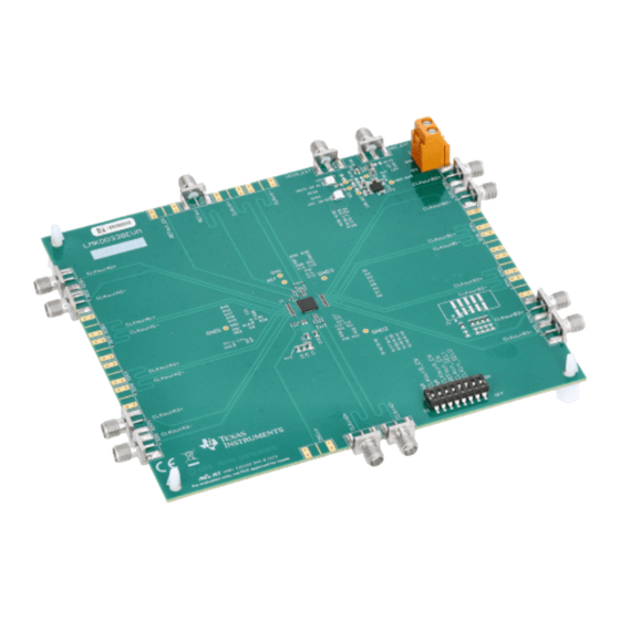
Board Layout www.ti.com Board Layout Figure 5. 3D PCB Print – Top (Not to Scale) SNAU155 – November 2013 LMK00338EVM User Guide Submit Documentation Feedback Copyright © 2013, Texas Instruments Incorporated... - Page 12 Board Layout www.ti.com Figure 6. 3D PCB Print – Bottom (Not to Scale) LMK00338EVM User Guide SNAU155 – November 2013 Submit Documentation Feedback Copyright © 2013, Texas Instruments Incorporated...
-
Page 13: Bill Of Materials
Bill of Materials www.ti.com Bill of Materials Table 5. LMK00338EVM Bill of Materials Designator Description Manufacturer Part Number Quantity !PCB Printed Circuit Board SV601035 C1, C4, C60, C64, C65, C67, CAP, CERM, 10uF, 10 V, MuRata GRM21BR61A106KE19L C71, C72 ±10%, X5R, 0805... - Page 14 Bill of Materials www.ti.com Table 5. LMK00338EVM Bill of Materials (continued) Designator Description Manufacturer Part Number Quantity R157 RES, 51k Ω, 5%, 0.1 W, Vishay-Dale CRCW060351K0JNEA 0603 R158 RES, 2.00k Ω, 1%, 0.1 W, Vishay-Dale CRCW06032K00FKEA 0603 RES, 866 Ω, 1%, 0.1 W,...
- Page 15 STANDARD TERMS AND CONDITIONS FOR EVALUATION MODULES Delivery: TI delivers TI evaluation boards, kits, or modules, including any accompanying demonstration software, components, or documentation (collectively, an “EVM” or “EVMs”) to the User (“User”) in accordance with the terms and conditions set forth herein. Acceptance of the EVM is expressly subject to the following terms and conditions.
- Page 16 FCC Interference Statement for Class B EVM devices NOTE: This equipment has been tested and found to comply with the limits for a Class B digital device, pursuant to part 15 of the FCC Rules. These limits are designed to provide reasonable protection against harmful interference in a residential installation.
- Page 17 【無線電波を送信する製品の開発キットをお使いになる際の注意事項】 開発キットの中には技術基準適合証明を受けて いないものがあります。 技術適合証明を受けていないもののご使用に際しては、電波法遵守のため、以下のいずれかの 措置を取っていただく必要がありますのでご注意ください。 1. 電波法施行規則第6条第1項第1号に基づく平成18年3月28日総務省告示第173号で定められた電波暗室等の試験設備でご使用 いただく。 2. 実験局の免許を取得後ご使用いただく。 3. 技術基準適合証明を取得後ご使用いただく。 なお、本製品は、上記の「ご使用にあたっての注意」を譲渡先、移転先に通知しない限り、譲渡、移転できないものとします。 上記を遵守頂けない場合は、電波法の罰則が適用される可能性があることをご留意ください。 日本テキサス・イ ンスツルメンツ株式会社 東京都新宿区西新宿6丁目24番1号 西新宿三井ビル 3.3.3 Notice for EVMs for Power Line Communication: Please see http://www.tij.co.jp/lsds/ti_ja/general/eStore/notice_02.page 電力線搬送波通信についての開発キットをお使いになる際の注意事項については、次のところをご覧くださ い。http://www.tij.co.jp/lsds/ti_ja/general/eStore/notice_02.page SPACER EVM Use Restrictions and Warnings: 4.1 EVMS ARE NOT FOR USE IN FUNCTIONAL SAFETY AND/OR SAFETY CRITICAL EVALUATIONS, INCLUDING BUT NOT LIMITED TO EVALUATIONS OF LIFE SUPPORT APPLICATIONS.
- Page 18 Notwithstanding the foregoing, any judgment may be enforced in any United States or foreign court, and TI may seek injunctive relief in any United States or foreign court. Mailing Address: Texas Instruments, Post Office Box 655303, Dallas, Texas 75265 Copyright © 2015, Texas Instruments Incorporated...
- Page 19 IMPORTANT NOTICE Texas Instruments Incorporated and its subsidiaries (TI) reserve the right to make corrections, enhancements, improvements and other changes to its semiconductor products and services per JESD46, latest issue, and to discontinue any product or service per JESD48, latest issue.
- Page 20 Mouser Electronics Authorized Distributor Click to View Pricing, Inventory, Delivery & Lifecycle Information: Texas Instruments LMK00338EVM...
Need help?
Do you have a question about the LMK00338EVM and is the answer not in the manual?
Questions and answers