Advertisement
Quick Links
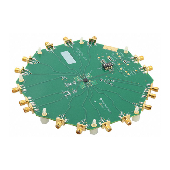
This user guide describes how to set up and operate the LMK00101 evaluation board kit (EVK). The
LMK00101 is a high performance, low noise, low voltage CMOS fanout buffer. The core voltage can be
2.5 or 3.3 volts, while the power supply for the outputs can be selected from: 1.5 V, 1.8 V, 2.5 V, or 3.3 V,
provided that it does not exceed the core supply voltage .
...................................................................................................................
1
Introduction
....................................................................................................................
2
Quick Start
2.1
Quick Start Description
3
Signal Path and Control Switches
4
Power Supplies
5
Clock Inputs
5.1
Crystal Oscillator Interface
5.2
Configuring OSCin for a Crystal Mode
6
Clock Outputs
...................................................................................................................
7
Schematics
...................................................................................................................
8
PCB Layout
9
Bill of Materials
1
LMK00101 Quick Start Setup
2
Schematic Sheet 1
3
Schematic Sheet 2
......................................................................................................................
4
PCB Top
5
Bottom Side (Layer Inverted, Not to Scale)
1
Part Description
2
Default Clock Output Modes / Interfaces
3
Input Selection (0=SW OFF, 1=SW ON)
4
Output Enable Selection (0=OFF, 1=ON)
5
Power Supply Configuration
6
Bill of Materials
Trademarks
All trademarks are the property of their respective owners.
SNLU098A – March 2012 – Revised July 2019
Submit Documentation Feedback
.............................................................................................
.........................................................................................
..............................................................................................................
..................................................................................................................
.........................................................................................
................................................................................................................
...............................................................................................................
..............................................................................................
..........................................................................................................
..........................................................................................................
..............................................................................................................
.................................................................................
.................................................................................
................................................................................................
...............................................................................................................
Copyright © 2012–2019, Texas Instruments Incorporated
SNLU098A – March 2012 – Revised July 2019
LMK00101 User's Guide
Contents
...........................................................................
List of Figures
..............................................................................
List of Tables
................................................................................
User's Guide
LMK00101 User's Guide
2
2
3
3
4
4
4
4
4
5
7
9
2
5
6
7
8
2
3
3
3
4
9
1
Advertisement

Related Manuals for Texas Instruments LMK00101BEVAL/NOPB


Summary of Contents for Texas Instruments LMK00101BEVAL/NOPB
- Page 1 Output Enable Selection (0=OFF, 1=ON) ....................Power Supply Configuration ....................... Bill of Materials Trademarks All trademarks are the property of their respective owners. SNLU098A – March 2012 – Revised July 2019 LMK00101 User’s Guide Submit Documentation Feedback Copyright © 2012–2019, Texas Instruments Incorporated...
-
Page 2: Quick Start
Input Select DIP Switches CLKout0- CLKout6- CLKout5 CLKout9 Single Ended Differential Oscillator Input CLKin0 Figure 1. LMK00101 Quick Start Setup LMK00101 User’s Guide SNLU098A – March 2012 – Revised July 2019 Submit Documentation Feedback Copyright © 2012–2019, Texas Instruments Incorporated... - Page 3 All control pins are configured with the control switch, S3. The output enable logic is shown in Table Table 4. Output Enable Selection (0=OFF, 1=ON) CLKout ENABLE MODE S1[3]-OE Disabled/Hi-Z Enabled SNLU098A – March 2012 – Revised July 2019 LMK00101 User’s Guide Submit Documentation Feedback Copyright © 2012–2019, Texas Instruments Incorporated...
- Page 4 All clock outputs are LVCMOS. In the case that not all outputs are used, any unused outputs should be left floating. LMK00101 User’s Guide SNLU098A – March 2012 – Revised July 2019 Submit Documentation Feedback Copyright © 2012–2019, Texas Instruments Incorporated...
- Page 5 Schematics www.ti.com Schematics Figure 2. Schematic Sheet 1 SNLU098A – March 2012 – Revised July 2019 LMK00101 User’s Guide Submit Documentation Feedback Copyright © 2012–2019, Texas Instruments Incorporated...
- Page 6 Schematics www.ti.com Figure 3. Schematic Sheet 2 LMK00101 User’s Guide SNLU098A – March 2012 – Revised July 2019 Submit Documentation Feedback Copyright © 2012–2019, Texas Instruments Incorporated...
- Page 7 PCB Layout www.ti.com PCB Layout Figure 4. PCB Top SNLU098A – March 2012 – Revised July 2019 LMK00101 User’s Guide Submit Documentation Feedback Copyright © 2012–2019, Texas Instruments Incorporated...
- Page 8 PCB Layout www.ti.com Figure 5. Bottom Side (Layer Inverted, Not to Scale) LMK00101 User’s Guide SNLU098A – March 2012 – Revised July 2019 Submit Documentation Feedback Copyright © 2012–2019, Texas Instruments Incorporated...
-
Page 9: Bill Of Materials
R33, R34, R40, R41, R42, Vishay-Dale CRCW06030000Z0EA 0603 R43, R309 RES, 4.7k ohm, 5%, 0.1W, R300, R301, R302 Vishay-Dale CRCW06034K70JNEA 0603 SNLU098A – March 2012 – Revised July 2019 LMK00101 User’s Guide Submit Documentation Feedback Copyright © 2012–2019, Texas Instruments Incorporated... - Page 10 Regulator for 1V to 5V Applications, 8-pin LLP, Pb-Free uWire, Vdd_TB, VddCLKout_TB Crystal, xxxMHz, xxpF, [MountType] Crystal, Citizen CS325, XXMHz LMK00101 User’s Guide SNLU098A – March 2012 – Revised July 2019 Submit Documentation Feedback Copyright © 2012–2019, Texas Instruments Incorporated...
-
Page 11: Revision History
NOTE: Page numbers for previous revisions may differ from page numbers in the current version. Changes from Original (March 2012) to A Revision ....................... Page ......................• Changed document throughout. SNLU098A – March 2012 – Revised July 2019 Revision History Submit Documentation Feedback Copyright © 2012–2019, Texas Instruments Incorporated... -
Page 12: Important Notice
TI products. TI’s provision of these resources does not expand or otherwise alter TI’s applicable warranties or warranty disclaimers for TI products. TI objects to and rejects any additional or different terms you may have proposed. IMPORTANT NOTICE Mailing Address: Texas Instruments, Post Office Box 655303, Dallas, Texas 75265 Copyright © 2022, Texas Instruments Incorporated...
Need help?
Do you have a question about the LMK00101BEVAL/NOPB and is the answer not in the manual?
Questions and answers