Advertisement
LMK61E2-156M25EVM
LMK61A2-156M25EVM
LMK61E2-312M50EVM
LMK61A2-312M50EVM
LMK61E2-100M00EVM
LMK61A2-100M00EVM
LMK61I2-100M00EVM
LMK61E2-125M00EVM
LMK61A2-125M00EVM
User's Guide
Literature Number: SNAU192A
November 2015 – Revised November 2015
This datasheet has been downloaded from
http://www.digchip.com
at this
page
Advertisement
Table of Contents

Related Manuals for Texas Instruments LMK61E2-156M25EVM


Summary of Contents for Texas Instruments LMK61E2-156M25EVM
- Page 1 LMK61E2-156M25EVM LMK61A2-156M25EVM LMK61E2-312M50EVM LMK61A2-312M50EVM LMK61E2-100M00EVM LMK61A2-100M00EVM LMK61I2-100M00EVM LMK61E2-125M00EVM LMK61A2-125M00EVM User's Guide Literature Number: SNAU192A November 2015 – Revised November 2015 This datasheet has been downloaded from http://www.digchip.com at this page...
- Page 2 LMK61E2-100M00EVM LMK61E2-100M00SIA 5 mm x 7 mm 8-pin QFM (SIA) LMK61A2-100M00EVM LMK61A2-100M00SIA LMK61I2-100M00EVM LMK61I2-100M00SIA LMK61E2-125M00EVM LMK61E2-125M00SIA LMK61A2-125M00EVM LMK61A2-125M00SIA User's Guide for LMK61XX EVMs SNAU192A – November 2015 – Revised November 2015 Submit Documentation Feedback Copyright © 2015, Texas Instruments Incorporated...
-
Page 3: Evm Configuration
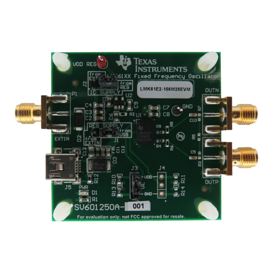
LMK61XX EVM without the need for external power supplies. These SMA ports are labeled in the top silkscreen layer. Figure 2. LMK61XX EVM Board Layout SNAU192A – November 2015 – Revised November 2015 User's Guide for LMK61XX EVMs Submit Documentation Feedback Copyright © 2015, Texas Instruments Incorporated... - Page 4 NOTE: Power delivery over the USB interface is subject to limitations of specific USB ports. Certain systems may require the use of an external supplied power source for proper operation. User's Guide for LMK61XX EVMs SNAU192A – November 2015 – Revised November 2015 Submit Documentation Feedback Copyright © 2015, Texas Instruments Incorporated...
- Page 5 100 ohm differential termination (R5) is provided on the LMK61XX EVM. Removing the differential termination on the EVM is possible if the differential termination is available on the receiver. SNAU192A – November 2015 – Revised November 2015 User's Guide for LMK61XX EVMs Submit Documentation Feedback Copyright © 2015, Texas Instruments Incorporated...
-
Page 6: Recommended Test Equipment
Oscilloscope: Agilent DSA90000A series (or equivalent) for AC measurements and time-domain jitter analysis with jitter software package • Balun: M/A-COM H-183-4 (30-3000 MHz) 180° coupler, or equivalent User's Guide for LMK61XX EVMs SNAU192A – November 2015 – Revised November 2015 Submit Documentation Feedback Copyright © 2015, Texas Instruments Incorporated... - Page 7 Figure 5. Phase Noise of LVPECL Differential Figure 6. Phase Noise of LVDS Differential Output at 156.25 MHz Output at 156.25 MHz SNAU192A – November 2015 – Revised November 2015 User's Guide for LMK61XX EVMs Submit Documentation Feedback Copyright © 2015, Texas Instruments Incorporated...
- Page 8 EVM Design www.ti.com EVM Design EVM Layout Figure 7. Top Overlay Figure 8. Top Solder Mask User's Guide for LMK61XX EVMs SNAU192A – November 2015 – Revised November 2015 Submit Documentation Feedback Copyright © 2015, Texas Instruments Incorporated...
- Page 9 EVM Design www.ti.com Figure 9. Layer 1 (Top Side) Figure 10. Layer 4 (Bottom Side, View From Bottom) SNAU192A – November 2015 – Revised November 2015 User's Guide for LMK61XX EVMs Submit Documentation Feedback Copyright © 2015, Texas Instruments Incorporated...
- Page 10 EVM Design www.ti.com Figure 11. Bottom Solder Mask Figure 12. Drill Drawing User's Guide for LMK61XX EVMs SNAU192A – November 2015 – Revised November 2015 Submit Documentation Feedback Copyright © 2015, Texas Instruments Incorporated...
- Page 11 EVM Design www.ti.com Figure 13. Board Dimensions SNAU192A – November 2015 – Revised November 2015 User's Guide for LMK61XX EVMs Submit Documentation Feedback Copyright © 2015, Texas Instruments Incorporated...
- Page 12 Default Shunt settings: SH3_2_3 means short Pins 2-3 of J5 jumper. Assembly Note Default Shunt settings: SH4_2_3 means short Pins 2-3 of J6 jumper. User's Guide for LMK61XX EVMs SNAU192A – November 2015 – Revised November 2015 Submit Documentation Feedback Copyright © 2015, Texas Instruments Incorporated...
- Page 13 1.5k 4 = U2A 4 = U2A 10µF 0.1µF 1SMB5922BT3G 22µF 7.5V 0805 1734035-2 1.5k 1.5k SH3_2_3 SH4_2_3 SNAU192A – November 2015 – Revised November 2015 User's Guide for LMK61XX EVMs Submit Documentation Feedback Copyright © 2015, Texas Instruments Incorporated...
- Page 14 R3, R7 RES, 0 ohm, 5%, 0.1W, 0603 Vishay-Dale CRCW06030000Z0EA RES, 100, 1%, 0.1 W, 0603 Vishay-Dale CRCW0603100RFKEA User's Guide for LMK61XX EVMs SNAU192A – November 2015 – Revised November 2015 Submit Documentation Feedback Copyright © 2015, Texas Instruments Incorporated...
-
Page 15: Revision History
Page ......................... • Production Data release. NOTE: Page numbers for previous revisions may differ from page numbers in the current version. SNAU192A – November 2015 – Revised November 2015 Revision History Submit Documentation Feedback Copyright © 2015, Texas Instruments Incorporated... - Page 16 STANDARD TERMS AND CONDITIONS FOR EVALUATION MODULES Delivery: TI delivers TI evaluation boards, kits, or modules, including any accompanying demonstration software, components, or documentation (collectively, an “EVM” or “EVMs”) to the User (“User”) in accordance with the terms and conditions set forth herein. Acceptance of the EVM is expressly subject to the following terms and conditions.
- Page 17 FCC Interference Statement for Class B EVM devices NOTE: This equipment has been tested and found to comply with the limits for a Class B digital device, pursuant to part 15 of the FCC Rules. These limits are designed to provide reasonable protection against harmful interference in a residential installation.
- Page 18 【無線電波を送信する製品の開発キットをお使いになる際の注意事項】 開発キットの中には技術基準適合証明を受けて いないものがあります。 技術適合証明を受けていないもののご使用に際しては、電波法遵守のため、以下のいずれかの 措置を取っていただく必要がありますのでご注意ください。 1. 電波法施行規則第6条第1項第1号に基づく平成18年3月28日総務省告示第173号で定められた電波暗室等の試験設備でご使用 いただく。 2. 実験局の免許を取得後ご使用いただく。 3. 技術基準適合証明を取得後ご使用いただく。 なお、本製品は、上記の「ご使用にあたっての注意」を譲渡先、移転先に通知しない限り、譲渡、移転できないものとします。 上記を遵守頂けない場合は、電波法の罰則が適用される可能性があることをご留意ください。 日本テキサス・イ ンスツルメンツ株式会社 東京都新宿区西新宿6丁目24番1号 西新宿三井ビル 3.3.3 Notice for EVMs for Power Line Communication: Please see http://www.tij.co.jp/lsds/ti_ja/general/eStore/notice_02.page 電力線搬送波通信についての開発キットをお使いになる際の注意事項については、次のところをご覧くださ い。http://www.tij.co.jp/lsds/ti_ja/general/eStore/notice_02.page SPACER EVM Use Restrictions and Warnings: 4.1 EVMS ARE NOT FOR USE IN FUNCTIONAL SAFETY AND/OR SAFETY CRITICAL EVALUATIONS, INCLUDING BUT NOT LIMITED TO EVALUATIONS OF LIFE SUPPORT APPLICATIONS.
- Page 19 Notwithstanding the foregoing, any judgment may be enforced in any United States or foreign court, and TI may seek injunctive relief in any United States or foreign court. Mailing Address: Texas Instruments, Post Office Box 655303, Dallas, Texas 75265 Copyright © 2015, Texas Instruments Incorporated...
-
Page 20: Important Notice
IMPORTANT NOTICE Texas Instruments Incorporated and its subsidiaries (TI) reserve the right to make corrections, enhancements, improvements and other changes to its semiconductor products and services per JESD46, latest issue, and to discontinue any product or service per JESD48, latest issue. - Page 21 Mouser Electronics Authorized Distributor Click to View Pricing, Inventory, Delivery & Lifecycle Information: Texas Instruments LMK61E2EVM LMK61E2-100M00EVM LMK61E2-125M00EVM LMK61E2-156M25EVM LMK61E2-312M50EVM...
Need help?
Do you have a question about the LMK61E2-156M25EVM and is the answer not in the manual?
Questions and answers