Table of Contents
Advertisement
Quick Links
www.ti.com
User's Guide
LMK04368EPEVM User's Guide
The LMK04368EPEVM (EVM) is designed to evaluate the performance and features of the LMK04368-EP high
performance Ultra-Low-Noise JESD204B Dual-Loop Clock Jitter Cleaner from Texas Instruments. The user's
guide describes how to set up and operate the EVM. The LMK04368-EP device on each EVM is an Engineering
Model, intended for engineering evaluation only.
Contents..............................................................................................................................................2
Start...............................................................................................................................................................................2
2.1 Quick Start Description......................................................................................................................................................
Filter.................................................................................................................................................................4
Filter.................................................................................................................................................................4
4 Default TICS Pro Mode...........................................................................................................................................................
5 Using TICS Pro to Program the LMK04368-EP....................................................................................................................
5.1 Start TICS Pro Application.................................................................................................................................................
5.2 Select Device.....................................................................................................................................................................
5.3 Program the Device...........................................................................................................................................................
5.4 Restoring a Default Mode..................................................................................................................................................
5.6 Enable Clock Outputs........................................................................................................................................................
6 Evaluation Board Inputs and Outputs..................................................................................................................................
7 Recommended Test Equipment..........................................................................................................................................
8
Schematics............................................................................................................................................................................13
9 Bill of Materials.....................................................................................................................................................................
Upgrade..............................................................................................................................................21
B TICS Pro Usage....................................................................................................................................................................
11.1 Communication Setup....................................................................................................................................................
Controls..................................................................................................................................................................26
Page.......................................................................................................................................................27
Page.............................................................................................................................................................28
Page................................................................................................................................................................29
11.6 CLKinX Control Page.....................................................................................................................................................
Page............................................................................................................................................................31
Page...................................................................................................................................................32
Page........................................................................................................................................................33
11.10 Other Page...................................................................................................................................................................
11.11 Burst Mode Page..........................................................................................................................................................
Trademarks
PLLatinum
™
is a trademark of Texas Instruments.
All trademarks are the property of their respective owners.
SNAU283 - OCTOBER 2022
Submit Document Feedback
ABSTRACT
Table of Contents
Parameters................................................................................................................................4
Lock..............................................................................................................................7
Copyright © 2022 Texas Instruments Incorporated
Table of Contents
LMK04368EPEVM User's Guide
2
5
5
5
5
6
6
7
9
12
16
25
25
30
34
35
1
Advertisement
Table of Contents

Subscribe to Our Youtube Channel
Related Manuals for Texas Instruments LMK04368EPEVM


Summary of Contents for Texas Instruments LMK04368EPEVM
-
Page 1: Table Of Contents
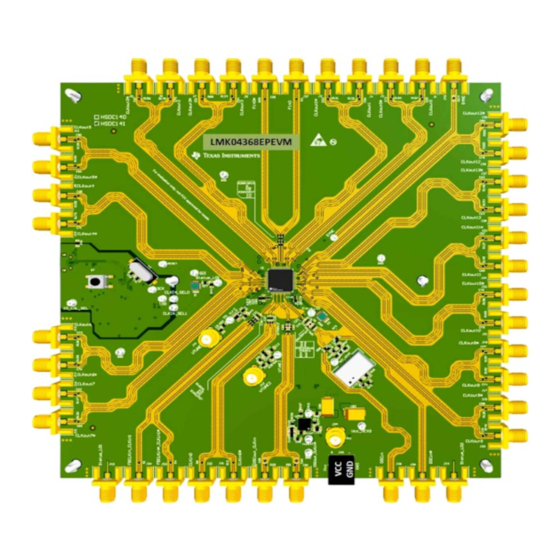
LMK04368EPEVM User’s Guide ABSTRACT The LMK04368EPEVM (EVM) is designed to evaluate the performance and features of the LMK04368-EP high performance Ultra-Low-Noise JESD204B Dual-Loop Clock Jitter Cleaner from Texas Instruments. The user’s guide describes how to set up and operate the EVM. The LMK04368-EP device on each EVM is an Engineering Model, intended for engineering evaluation only. -
Page 2: Evaluation Board Kit Contents
Table 1-1. EVM Contents HSDC141 Evaluation Board LMK04368EPEVM Evaluation Board with VCXO (1) USB cable USB Cable A Plug to Micro B Plug cable (1) 2 Quick Start Figure 2-1. Quick Start Diagram Related information: http://www.ti.com/tool/ticspro-sw... - Page 3 No effect for CLKoutX in bypass mode. 17. CLKoutX_Y_PD: Power down the entire CLKoutX_Y clock pair. 18. SCLKX_Y_DDLY: The SYSREF clock digital delay setting. SNAU283 – OCTOBER 2022 LMK04368EPEVM User’s Guide Submit Document Feedback Copyright © 2022 Texas Instruments Incorporated...
-
Page 4: Pll Loop Filters And Loop Parameters
The loop filters on the LMK04368EPEVM evaluation board are set up using the approach above. The loop filter for PLL1 has been configured for a narrow loop bandwidth (< 1 kHz). The specific loop bandwidth values depend on the phase noise performance of the oscillator mounted on the board. -
Page 5: Default Tics Pro Mode
5.1 Start TICS Pro Application Click Start → Programs → Texas Instruments → TICS Pro. The TICS Pro program is installed by default to the Texas Instruments application group. 5.2 Select Device Click Select Device → Clock Generator/Jitter Cleaner (Dual Loop) → LMK04368-EP. -
Page 6: Program The Device
Click Default configuration → CLKin1 122.88 MHz, OSCin 122.88 MHz, VCO1 2949.12 MHz. Press Ctrl+L to restore the default configuration. Figure 5-3. Setting the Default Configuration for LMK04368-EP LMK04368EPEVM User’s Guide SNAU283 – OCTOBER 2022 Submit Document Feedback Copyright © 2022 Texas Instruments Incorporated... -
Page 7: Visual Confirmation Of Frequency Lock
For a simple continuous SYSREF (not recommended in final application due to extra power consumption and crosstalk), set SYSREF_PD = 0, SYSREF_MUX = 0x03 (Continuous), and SYNC_DISSYSREF = 1. SNAU283 – OCTOBER 2022 LMK04368EPEVM User’s Guide Submit Document Feedback Copyright © 2022 Texas Instruments Incorporated... - Page 8 TI recommends leaving the output floating close to the IC. Alternatively, place a 50-Ω termination at the end of an unused trace. 5. The phase noise may be measured with a spectrum analyzer or signal source analyzer. LMK04368EPEVM User’s Guide SNAU283 – OCTOBER 2022 Submit Document Feedback Copyright © 2022 Texas Instruments Incorporated...
-
Page 9: Evaluation Board Inputs And Outputs
(normal, inverted, inverted, and off/tri- state). Best performance/EMI reduction is achieved by using a complementary output mode like Norm/Inv. TI does NOT recommend using Norm/Norm or Inv/Inv mode. SNAU283 – OCTOBER 2022 LMK04368EPEVM User’s Guide Submit Document Feedback Copyright © 2022 Texas Instruments Incorporated... - Page 10 SIGNAL TYPE, INPUT/OUTPUT DESCRIPTION Main power supply input for the evaluation board. The LMK04368EPEVM default is setup to use the TPS7A4701-EP voltage regulator. This is a space grade (SEP) voltage regulator. 0-Ω resistors R93, R98 and R104 can be re-configured to route power through the on-board EP grade LDO, the TPS7A4701-EP.
- Page 11 By the default TICS Pro configuration, LEDs will illuminate green Status_LD2(TP7) when lock is detected (output is high) and turn off when lock is lost (output is low). SNAU283 – OCTOBER 2022 LMK04368EPEVM User’s Guide Submit Document Feedback Copyright © 2022 Texas Instruments Incorporated...
-
Page 12: Recommended Test Equipment
TI recommends using phase-matched, 50-Ω cables to minimize external sources of skew or other errors/distortion that may be introduced if using oscilloscope probes. LMK04368EPEVM User’s Guide SNAU283 – OCTOBER 2022 Submit Document Feedback Copyright © 2022 Texas Instruments Incorporated... -
Page 13: Schematics
8 Schematics The components on the EVM can be found on the following schematic by searching for their reference designators. Figure 8-1. Schematic - LMK04368-EP SNAU283 – OCTOBER 2022 LMK04368EPEVM User’s Guide Submit Document Feedback Copyright © 2022 Texas Instruments Incorporated... - Page 14 Schematics www.ti.com Figure 8-2. Schematic - Power Supply Figure 8-3. Schematic - Digital LMK04368EPEVM User’s Guide SNAU283 – OCTOBER 2022 Submit Document Feedback Copyright © 2022 Texas Instruments Incorporated...
- Page 15 Schematics Figure 8-4. Schematic - Clock Outputs 1 of 2 Figure 8-5. Schematic - Clock Outputs 2 of 2 SNAU283 – OCTOBER 2022 LMK04368EPEVM User’s Guide Submit Document Feedback Copyright © 2022 Texas Instruments Incorporated...
-
Page 16: Bill Of Materials
CAP, CERM, 82 pF, 50 V, +/- 10%, C0603C820K5GACTU 0603 Kemet C0G/NP0, 0603 CAP, CERM, 2.2 uF, 16 V, +/- 20%, 885012106018 0603 Wurth Elektronik X5R, 0603 LMK04368EPEVM User’s Guide SNAU283 – OCTOBER 2022 Submit Document Feedback Copyright © 2022 Texas Instruments Incorporated... - Page 17 MuRata 0.5 A, 0603 FB4, FB5, FB6, FB7, FB8, FB9, Ferrite Bead, 120 ohm @ 100 MHz, MMZ1005Y121CT000 0402 FB10, FB11 0.4 A, 0402 SNAU283 – OCTOBER 2022 LMK04368EPEVM User’s Guide Submit Document Feedback Copyright © 2022 Texas Instruments Incorporated...
- Page 18 R113, R209, R213, R216, R220, R226, R230, R232 R38, R49, R105, R123, R160, R176 RES, 240, 5%, 0.063 W, AEC-Q200 CRCW0402240RJNED 0402 Vishay-Dale Grade 0, 0402 LMK04368EPEVM User’s Guide SNAU283 – OCTOBER 2022 Submit Document Feedback Copyright © 2022 Texas Instruments Incorporated...
- Page 19 RES, 20.0, 1%, 0.063 W, AEC-Q200 CRCW040220R0FKED 0402 Vishay-Dale Grade 0, 0402 S1, S2, S3, S4, S5, S6 HEX STANDOFF SPACER, 9.53 mm TCBS-6-01 7.9x9.5 mm Richco Plastics SNAU283 – OCTOBER 2022 LMK04368EPEVM User’s Guide Submit Document Feedback Copyright © 2022 Texas Instruments Incorporated...
- Page 20 Texas Instruments Voltage Regulator, RGW0020A (VQFN-20) VCXO, CMOS 122.880 MHz, 3.3V, CVHD-950-122.880 CVHD-950-4 Crystek Corporation Crystal, 24.000 MHz, 20pF, SMD ECS-240-20-5PX-TR Crystal, 11.4x4.3x3.8mm ECS Inc. LMK04368EPEVM User’s Guide SNAU283 – OCTOBER 2022 Submit Document Feedback Copyright © 2022 Texas Instruments Incorporated...
-
Page 21: A Usb2Any Firmware Upgrade
2. The Firmware Loader pop-up window will load. Disconnect the USB cable from the EVM. Figure A-2. Firmware Loader 3. Press and hold the BSL button while you connect the USB2ANY cable. SNAU283 – OCTOBER 2022 LMK04368EPEVM User’s Guide Submit Document Feedback Copyright © 2022 Texas Instruments Incorporated... - Page 22 USB2ANY Firmware Upgrade www.ti.com Figure A-3. BSL Button Location LMK04368EPEVM User’s Guide SNAU283 – OCTOBER 2022 Submit Document Feedback Copyright © 2022 Texas Instruments Incorporated...
- Page 23 Figure A-4. Update Firmware 5. Click Upgrade Firmware to start the firmware upgrade. Click Close after the upgrade is complete. Figure A-5. Firmware Update Complete SNAU283 – OCTOBER 2022 LMK04368EPEVM User’s Guide Submit Document Feedback Copyright © 2022 Texas Instruments Incorporated...
- Page 24 6. Go to USB communications → Interface in the TICS Pro software to check the USB connection. Make sure the USB Connected button is green. Figure A-6. USB Communications LMK04368EPEVM User’s Guide SNAU283 – OCTOBER 2022 Submit Document Feedback Copyright © 2022 Texas Instruments Incorporated...
-
Page 25: B Tics Pro Usage
USB2ANY is currently selected. Devices used by other instances of TICS Pro will not display in this list. Figure 11-1. TICS Pro - Communication Setup Window SNAU283 – OCTOBER 2022 LMK04368EPEVM User’s Guide Submit Document Feedback Copyright © 2022 Texas Instruments Incorporated... -
Page 26: User Controls
The User Controls page has controls typically not included on one of the other dedicated pages. Figure 11-2. TICS Pro - User Controls Page LMK04368EPEVM User’s Guide SNAU283 – OCTOBER 2022 Submit Document Feedback Copyright © 2022 Texas Instruments Incorporated... -
Page 27: Raw Registers Page
Use the Export Register Map option to create a text file with the register values for simple re-use of the register configuration. Figure 11-3. TICS Pro - Raw Registers Page SNAU283 – OCTOBER 2022 LMK04368EPEVM User’s Guide Submit Document Feedback Copyright © 2022 Texas Instruments Incorporated... -
Page 28: Set Modes Page
The bottom LMK04832 sub-modes section allows further JESD204B configuration, 0-delay configuration, or clock input configuration which may apply for many of the LMK04832 modes of operation. Figure 11-4. TICS Pro - Set Modes Page LMK04368EPEVM User’s Guide SNAU283 – OCTOBER 2022 Submit Document Feedback Copyright © 2022 Texas Instruments Incorporated... -
Page 29: Holdover Page
In addition to the above steps, auto clock selection mode must be used to allow the LMK04832 to automatically switch to holdover when enabled clocks for auto switching (CLKinX_EN) are lost. Figure 11-5. TICS Pro - Holdover Page SNAU283 – OCTOBER 2022 LMK04368EPEVM User’s Guide Submit Document Feedback Copyright © 2022 Texas Instruments Incorporated... -
Page 30: Clkinx Control Page
CLKinX is selected, and change the routing options for the CLKinX inputs. You can also reset the PLL1 R or PLL2 N divider on this page. Figure 11-6. TICS Pro - CLKinX Control Page LMK04368EPEVM User’s Guide SNAU283 – OCTOBER 2022 Submit Document Feedback Copyright © 2022 Texas Instruments Incorporated... -
Page 31: Pll1 And 2 Page
Independent to allow the OSCin frequency to be unlinked from the external VCXO frequency. Figure 11-7. TICS Pro - PLL1 and 2 Page SNAU283 – OCTOBER 2022 LMK04368EPEVM User’s Guide Submit Document Feedback Copyright © 2022 Texas Instruments Incorporated... -
Page 32: Sync / Sysref Page
SYSREF_CLR = 1 during the transition to prevent glitch pulses from the SYSREF output. Figure 11-8. TICS Pro - SYNC / SYSREF Page LMK04368EPEVM User’s Guide SNAU283 – OCTOBER 2022 Submit Document Feedback Copyright © 2022 Texas Instruments Incorporated... -
Page 33: Clock Outputs Page
The naming convention uses X_Y for controls which can impact both CLKoutX (even clock) and CLKoutY (odd clock), X for controls impacting only CLKoutX and Y for controls impacting only CLKoutY. Figure 11-9. TICS Pro - Clock Outputs Page SNAU283 – OCTOBER 2022 LMK04368EPEVM User’s Guide Submit Document Feedback Copyright © 2022 Texas Instruments Incorporated... -
Page 34: Other Page
_TYPE field which allows the input or output mode of the pin to be defined. The second is the _MUX field which, when set for output, controls what the pin will output. Figure 11-10. TICS Pro - Other Page LMK04368EPEVM User’s Guide SNAU283 – OCTOBER 2022 Submit Document Feedback Copyright © 2022 Texas Instruments Incorporated... -
Page 35: Burst Mode Page
The Burst mode page allows the user to program sequences of register programming or pin control. Figure 11-11. TICS Pro - Burst Mode Page SNAU283 – OCTOBER 2022 LMK04368EPEVM User’s Guide Submit Document Feedback Copyright © 2022 Texas Instruments Incorporated... - Page 36 STANDARD TERMS FOR EVALUATION MODULES Delivery: TI delivers TI evaluation boards, kits, or modules, including any accompanying demonstration software, components, and/or documentation which may be provided together or separately (collectively, an “EVM” or “EVMs”) to the User (“User”) in accordance with the terms set forth herein.
- Page 37 www.ti.com Regulatory Notices: 3.1 United States 3.1.1 Notice applicable to EVMs not FCC-Approved: FCC NOTICE: This kit is designed to allow product developers to evaluate electronic components, circuitry, or software associated with the kit to determine whether to incorporate such items in a finished product and software developers to write software applications for use with the end product.
- Page 38 www.ti.com Concernant les EVMs avec antennes détachables Conformément à la réglementation d'Industrie Canada, le présent émetteur radio peut fonctionner avec une antenne d'un type et d'un gain maximal (ou inférieur) approuvé pour l'émetteur par Industrie Canada. Dans le but de réduire les risques de brouillage radioélectrique à...
- Page 39 www.ti.com EVM Use Restrictions and Warnings: 4.1 EVMS ARE NOT FOR USE IN FUNCTIONAL SAFETY AND/OR SAFETY CRITICAL EVALUATIONS, INCLUDING BUT NOT LIMITED TO EVALUATIONS OF LIFE SUPPORT APPLICATIONS. 4.2 User must read and apply the user guide and other available documentation provided by TI regarding the EVM prior to handling or using the EVM, including without limitation any warning or restriction notices.
- Page 40 Notwithstanding the foregoing, any judgment may be enforced in any United States or foreign court, and TI may seek injunctive relief in any United States or foreign court. Mailing Address: Texas Instruments, Post Office Box 655303, Dallas, Texas 75265 Copyright © 2019, Texas Instruments Incorporated...
- Page 41 TI products. TI’s provision of these resources does not expand or otherwise alter TI’s applicable warranties or warranty disclaimers for TI products. TI objects to and rejects any additional or different terms you may have proposed. IMPORTANT NOTICE Mailing Address: Texas Instruments, Post Office Box 655303, Dallas, Texas 75265 Copyright © 2022, Texas Instruments Incorporated...
Need help?
Do you have a question about the LMK04368EPEVM and is the answer not in the manual?
Questions and answers