Table of Contents
Advertisement
Quick Links
www.ti.com
User's Guide
LMK1D1208IEVM User's Guide
The LMK1D1208I is a high-performance, low-additive jitter LVDS clock buffer with two universal inputs, 8 LVDS
outputs, and I2C configurability.
This evaluation module (EVM) is designed to demonstrate the electrical performance of the LMK1D1208I.
Throughout this document, the acronym EVM and the phrases evaluation module and evaluation board are
synonymous with the LMK1D1208IEVM.
The LMK1D1208IEVM is equipped with 50-Ω SMA connectors and impedance-controlled, 50-Ω, microstrip
transmission lines for best performance.
SNAU270 – FEBRUARY 2022
Submit Document Feedback
ABSTRACT
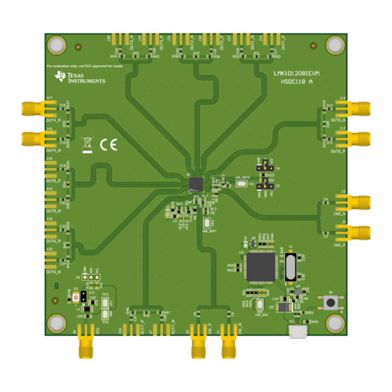
Figure 1-1. LMK1D1208I Evaluation Board
Copyright © 2022 Texas Instruments Incorporated
LMK1D1208IEVM User's Guide
1
Advertisement
Table of Contents

Related Manuals for Texas Instruments LMK1D1208IEVM


Summary of Contents for Texas Instruments LMK1D1208IEVM
- Page 1 Throughout this document, the acronym EVM and the phrases evaluation module and evaluation board are synonymous with the LMK1D1208IEVM. The LMK1D1208IEVM is equipped with 50-Ω SMA connectors and impedance-controlled, 50-Ω, microstrip transmission lines for best performance. Figure 1-1. LMK1D1208I Evaluation Board SNAU270 –...
-
Page 2: Table Of Contents
8.1 I2C Address Selection..............................9 EVM Board Schematic................................12 10 Bill of Materials................................... 11 REACH Compliance................................21 Trademarks All trademarks are the property of their respective owners. LMK1D1208IEVM User's Guide SNAU270 – FEBRUARY 2022 Submit Document Feedback Copyright © 2022 Texas Instruments Incorporated... -
Page 3: Features
8 LVDS outputs that operate at the selected input frequency. For more information, see the LMK1D1208I I2C Configurable Low Additive Jitter LVDS Buffer data sheet (SNAS828) for details. SNAU270 – FEBRUARY 2022 LMK1D1208IEVM User's Guide Submit Document Feedback Copyright © 2022 Texas Instruments Incorporated... -
Page 4: Getting Started
The bold italic text in this document follows the same spelling as the actual labeling on the EVM board. By default, the EVM can be used with differential inputs and, after board modification, with single-ended inputs. Figure 4-1. LMK1D1208IEVM Quick Start Guide LMK1D1208IEVM User's Guide SNAU270 –... -
Page 5: Power Supply Connection
A supply voltage of 1.71 V to 3.465 V can be used for this EVM. Figure 5-1. Power Supply Connection Layout SNAU270 – FEBRUARY 2022 LMK1D1208IEVM User's Guide Submit Document Feedback Copyright © 2022 Texas Instruments Incorporated... -
Page 6: Input Clock
TP2. Figure 6-1. Input Clock Selection Layout 6.1 Differential Input By default, the clock inputs are configured as AC-coupled LVDS inputs with VAC_REF connection. LMK1D1208IEVM User's Guide SNAU270 – FEBRUARY 2022 Submit Document Feedback Copyright © 2022 Texas Instruments Incorporated... -
Page 7: Single-Ended Input
C3, C4 IN0_P 1.25 2.5 (LVCMOS) IN1_N C5, C6 IN1_P 3.3 (LVCMOS) 1.65 IN0_N C3, C4 IN0_P 1.65 3.3 (LVCMOS) IN1_N C5, C6 IN1_P SNAU270 – FEBRUARY 2022 LMK1D1208IEVM User's Guide Submit Document Feedback Copyright © 2022 Texas Instruments Incorporated... -
Page 8: Output Clock
The LVDS outputs are AC-coupled to their respective SMAs. Each output pair has the 100-Ω termination on the board already populated. Figure 7-1. Output Clock EVM Layout LMK1D1208IEVM User's Guide SNAU270 – FEBRUARY 2022 Submit Document Feedback Copyright © 2022 Texas Instruments Incorporated... -
Page 9: Using I2C
Figure 8-1. Locate the LMK1D1208I Device Profile Using the same toolbar, click USB communications → Interface → USB2ANY to switch from DemoMode to I2C. Figure 8-2. Set to I2C Communication SNAU270 – FEBRUARY 2022 LMK1D1208IEVM User's Guide Submit Document Feedback Copyright © 2022 Texas Instruments Incorporated... - Page 10 TI highly recommends that the user only modifies the registers available in the Main tab. Using the LMK1D1208I beyond logic states allowed in the GUI should be avoided to ensure performance and prevent device misuse. Figure 8-3. LMK1D1208I GUI Main Page LMK1D1208IEVM User's Guide SNAU270 – FEBRUARY 2022 Submit Document Feedback Copyright © 2022 Texas Instruments Incorporated...
-
Page 11: I2C Address Selection
I2C address. Table 8-1. I2C Address Assignment I2C ADDRESS IDX1 IDX0 0x68 0x69 0x6A 0x6B Figure 8-4. I2C Address Selection Layout SNAU270 – FEBRUARY 2022 LMK1D1208IEVM User's Guide Submit Document Feedback Copyright © 2022 Texas Instruments Incorporated... -
Page 12: Evm Board Schematic
CK7 P OUT7_P CK7 P CK7 N OUT7_N CK7 N IDX0 IDX0 IDX0 IDX1 IDX1 IDX1 ThermalPad LMK1D1208IRHA Figure 9-1. LMK1D1208IEVM Schematic: Device Sheet LMK1D1208IEVM User's Guide SNAU270 – FEBRUARY 2022 Submit Document Feedback Copyright © 2022 Texas Instruments Incorporated... - Page 13 U2A_3V3 100nF 1.00k Yellow SDA_BACK 1.5k 1.5k SDA1 SDA1 SCL1 U2AGPIO0 SCL1 SCL_BACK PBC03SAAN U2AGPIO1 1.00k 10pF 10pF Figure 9-2. LMK1D1208IEVM Schematic: Inputs Sheet SNAU270 – FEBRUARY 2022 LMK1D1208IEVM User's Guide Submit Document Feedback Copyright © 2022 Texas Instruments Incorporated...
- Page 14 0.1µF 0.1µF 0.1µF CON-SMA-EDGE-S CON-SMA-EDGE-S CON-SMA-EDGE-S CK4 N CK5 N CK6 N CK7 N 0.1µF 0.1µF 0.1µF 0.1µF Figure 9-3. LMK1D1208IEVM Schematic: Outputs Sheet LMK1D1208IEVM User's Guide SNAU270 – FEBRUARY 2022 Submit Document Feedback Copyright © 2022 Texas Instruments Incorporated...
- Page 15 VDD = 1.8V / 2.5V / 3.3V @ 300mA (max) CON-SMA-EDGE-S 10µF 0.22uF 0.22uF 0.22uF 0.22uF 0.22uF 0.22uF 0.22uF 1µF Figure 9-4. LMK1D1208IEVM Schematic: Power Supply Sheet SNAU270 – FEBRUARY 2022 LMK1D1208IEVM User's Guide Submit Document Feedback Copyright © 2022 Texas Instruments Incorporated...
- Page 16 LMK1D1208IEVM User's Guide SNAU270 – FEBRUARY 2022 warrant that this design will meet the specifications, will be suitable for your application or fit for any particular purpose, or will operate in an implementation. Texas Instruments and/or its Drawn By: Aaron Black File: HSDC118A_USB.SchDoc...
-
Page 17: Bill Of Materials
Lite-On SMD RED LED SMD_LED BOS-3528-2RCQ 7.5V Diode, Zener, 7.5 V, 550 1SMB5922BT3G ON Semiconductor mW, SMB Green LED, Green, SMD 1.6x0.8x0.8mm LTST-C190GKT Lite-On SNAU270 – FEBRUARY 2022 LMK1D1208IEVM User's Guide Submit Document Feedback Copyright © 2022 Texas Instruments Incorporated... - Page 18 RES, 100, 1%, 0.1 W, 0603 CRCW0603100RFKEA Vishay-Dale AEC-Q200 Grade 0, 0603 R49, R58 RES, 33 k, 5%, 0.1 W, 0603 CRCW060333K0JNEA Vishay-Dale AEC-Q200 Grade 0, 0603 LMK1D1208IEVM User's Guide SNAU270 – FEBRUARY 2022 Submit Document Feedback Copyright © 2022 Texas Instruments Incorporated...
- Page 19 FID1, FID2, FID3, FID4, Fiducial mark. There is FID5, FID6 nothing to buy or mount. Header, 100mil, 3x1, PBC03SAAN PBC03SAAN Sullins Connector Gold, TH Solutions SNAU270 – FEBRUARY 2022 LMK1D1208IEVM User's Guide Submit Document Feedback Copyright © 2022 Texas Instruments Incorporated...
- Page 20 RES, 0, 5%, 0.1 W, AEC- 0603 CRCW06030000Z0EA Vishay-Dale Q200 Grade 0, 0603 RES, 33 k, 5%, 0.1 W, 0603 CRCW060333K0JNEA Vishay-Dale AEC-Q200 Grade 0, 0603 LMK1D1208IEVM User's Guide SNAU270 – FEBRUARY 2022 Submit Document Feedback Copyright © 2022 Texas Instruments Incorporated...
-
Page 21: Reach Compliance
In compliance with the Article 33 provision of the EU REACH regulation we are notifying you that this EVM includes component(s) containing at least one Substance of Very High Concern (SVHC) above 0.1%. These uses from Texas Instruments do not exceed 1 ton per year. The SVHC’s are: Component... - Page 22 STANDARD TERMS FOR EVALUATION MODULES Delivery: TI delivers TI evaluation boards, kits, or modules, including any accompanying demonstration software, components, and/or documentation which may be provided together or separately (collectively, an “EVM” or “EVMs”) to the User (“User”) in accordance with the terms set forth herein.
- Page 23 www.ti.com Regulatory Notices: 3.1 United States 3.1.1 Notice applicable to EVMs not FCC-Approved: FCC NOTICE: This kit is designed to allow product developers to evaluate electronic components, circuitry, or software associated with the kit to determine whether to incorporate such items in a finished product and software developers to write software applications for use with the end product.
- Page 24 www.ti.com Concernant les EVMs avec antennes détachables Conformément à la réglementation d'Industrie Canada, le présent émetteur radio peut fonctionner avec une antenne d'un type et d'un gain maximal (ou inférieur) approuvé pour l'émetteur par Industrie Canada. Dans le but de réduire les risques de brouillage radioélectrique à...
- Page 25 www.ti.com EVM Use Restrictions and Warnings: 4.1 EVMS ARE NOT FOR USE IN FUNCTIONAL SAFETY AND/OR SAFETY CRITICAL EVALUATIONS, INCLUDING BUT NOT LIMITED TO EVALUATIONS OF LIFE SUPPORT APPLICATIONS. 4.2 User must read and apply the user guide and other available documentation provided by TI regarding the EVM prior to handling or using the EVM, including without limitation any warning or restriction notices.
- Page 26 Notwithstanding the foregoing, any judgment may be enforced in any United States or foreign court, and TI may seek injunctive relief in any United States or foreign court. Mailing Address: Texas Instruments, Post Office Box 655303, Dallas, Texas 75265 Copyright © 2019, Texas Instruments Incorporated...
- Page 27 TI products. TI’s provision of these resources does not expand or otherwise alter TI’s applicable warranties or warranty disclaimers for TI products. TI objects to and rejects any additional or different terms you may have proposed. IMPORTANT NOTICE Mailing Address: Texas Instruments, Post Office Box 655303, Dallas, Texas 75265 Copyright © 2022, Texas Instruments Incorporated...
Need help?
Do you have a question about the LMK1D1208IEVM and is the answer not in the manual?
Questions and answers