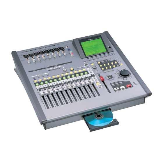
Roland VS-2400CD Appendices
24tr / 24-bit / 96khz digital studio workstation
Hide thumbs
Also See for VS-2400CD:
- Owner's manual (508 pages) ,
- Service notes (49 pages) ,
- Mixer block diagram (1 page)
Table of Contents
Advertisement
Appendices
Before using this unit, carefully read the sections entitled: "IMPORTANT
SAFETY INSTRUCTIONS" (Owner's Manual p. 2), "USING THE UNIT
SAFELY" (Owner's Manual p. 3), and "IMPORTANT NOTES" (Owner's
Manual p. 5). These sections provide important information concerning the
proper operation of the unit. Additionally, in order to feel assured that you
have gained a good grasp of every feature provided by your new unit,
Owner's Manual, and Appendices should be read in its entirety. These
manuals should be saved and kept on hand as a convenient reference.
Copyright © 2002 ROLAND CORPORATION
All rights reserved. No part of this publication may be reproduced in any form
without the written permission of ROLAND CORPORATION.
Roland International Web Site: http://www.Roland.com
Roland US Web Site:
http://www.RolandUS.com
Advertisement
Table of Contents

Related Manuals for Roland VS-2400CD


Summary of Contents for Roland VS-2400CD
- Page 1 Copyright © 2002 ROLAND CORPORATION All rights reserved. No part of this publication may be reproduced in any form without the written permission of ROLAND CORPORATION. Roland International Web Site: http://www.Roland.com Roland US Web Site:...
-
Page 3: Table Of Contents
Contents About MIDI ...4 Troubleshooting...5 Q&A ...8 BASIC FUNCTIONS ... 8 EFFECTS ... 9 CD-R/RW DRIVE ... 10 DIGITAL I/O ... 11 MIDI DEVICES ... 12 DATA COMPATIBILITY WITH OTHER VS MODELS ... 12 OTHERS... 13 How to Record with External Effects Devices Connected ... 14 Error Messages ...16 Glossary...18 Shortcut Key Operations...21... -
Page 4: About Midi
Exclusive messages: Unlike note messages and control change messages, exclusive messages are used to transmit settings that are unique to a particular device. On the VS-2400CD, they can be used to control VS-2400CD mixer parameters, when it receives exclusive messages. -
Page 5: Troubleshooting
Troubleshooting When the VS-2400CD does not perform the way you expect, check the following points before you suspect a malfunction. If this does not resolve the problem, Contact your dealer or a qualified Roland Service Center. Recording and Play back No Sound •... -
Page 6: Internal Effects
→ Some digital audio devices do not output a digital signal unless they are in play mode. If this is the case, put your digital audio device in standby (pause) mode before putting the VS-2400CD into record mode. • The digital signal format is different. -
Page 7: Other Problems
• The MIDI cable is broken. • You are trying to synchronize using the MIDI clock. → The VS-2400CD cannot be run in slave mode using a method other than MTC. • The EXT indicator is off (“SYNC MODE” is set to “INT”). -
Page 8: Q&A
VS-2400CD’s 24-bit A/D converter, and audio data from the 24-bit digital inputs will be recorded and played as linear data. When this mode is selected, the VS-2400CD will function as a 16-track recorder (tracks 1–16). When sampling frequency is more than 64kHz, the VS-2400CD will function as a 8-track recorder. -
Page 9: Effects
Q: Is it possible to insert the external effect processor to the channel? A: Insert connector is not equipped on VS-2400CD but it is possible to use the external effect processors. Please refer to the this manual “How to Record with External Effects Devices Connected (p. -
Page 10: Cd-R/Rw Drive
A: P and Q sub channel information is not generated by the VS-2400CD, but the CD-R/RW drive automatically generates these in accordance with the CUE sheet from the VS-2400CD. In other words, the required markers for an audio CD such... -
Page 11: Digital I/O
VS-2400CD? Are R-BUS cables sold separately? A: VS-2400CD is equipped with one R-BUS connector. An R-BUS cable does not come with VS-2400CD. Please use the cable which is attached to the external R-BUS devices, or order the following cables. -
Page 12: Midi Devices
Q: Is it possible to use a digital input when the VS-2400CD is an MTC slave? A: Yes. But if the discrepancy between the MTC and the digital master clock gets large, the VS-2400CD may stop play back. Q: Is it possible to assign any MIDI... -
Page 13: Others
Q: Is it possible to use a pen tablet or track ball instead of the attached mouse? A: Mouse port conforms to PS/2 but Roland does not officially support other devices than the attached mouse. Q: Is it possible to write the Project in... -
Page 14: How To Record With External Effects Devices Connected
Using Track Direct Outs Sounds recorded to Tracks 9–16 are output from ANALOG MULTI OUTPUT 1–8, external effects are added, and the sounds are returned to inputs in the VS-2400CD and recorded to Tracks 1–8. Externally Outputting Tracks 9–16 1. Press [TR1-12]. - Page 15 19. In the same way, assign Inputs 3, 4, 5, 6, 7, and 8 to Tracks 3, 4, 5, 6, 7, and 8, respectively. 20. Press [HOME]. The VS-2400CD switches to Home condition. 21. Press [REC]. The VS-2400CD enters recording standby mode.
-
Page 16: Cannot Write In "Track At Once" Format On Cd-Rw Disc
Drive Busy! If this message appears when you first begin using a disk drive with the VS-2400CD, the disk drive is not fast enough. You may still be able to use this disk with projects that have a lower sample rate or use a different recording mode. -
Page 17: Fx Board For Rss Pan Is Not Installed
Track 0 Not Found! Medium Error! There is a problem with the disk drive media or CD. This disk cannot be used by the VS-2400CD. In some cases, data in the disk drive can be recovered using the Drive Check operation. -
Page 18: Current Project
Stands for Composite Object Sound Modeling. This is “a technology which combines multiple sound models to create new sounds,” which was first used on the Roland’s VG-8 V- Guitar System. For example, sounds created on the VG-8 are the result of a variety of sound models (elements) such as the pickup, the body of the guitar, the guitar amp, mic, and speaker etc. -
Page 19: Phantom Power
By connecting this control jack to the foot switch jack of the VS-2400CD and setting the Foot Switch Assign to “GPI,” the connected device will be able to play back/stop the VS-2400CD. -
Page 20: Track Minutes
It should NOT be connected to other types of ports that use similar connectors! RSS stands for Roland Sound Space. This is an effect which allows a sound source to be placed in three-dimensional space when played back on a conventional stereo system. -
Page 21: Ch Edit/Select/Automix Status Buttons
Shortcut Key Operations Here is a list of the functions that can be performed by pressing multiple buttons, or using the TIME/VALUE dial in conjunction with a button. CH EDIT/SELECT/AUTOMIX STATUS buttons [AUTOMIX] + [AUTOMIX STATUS] (*1) [SHIFT] + [CH EDIT] [CH EDIT] + [CH EDIT] (*2) (*1) INPUT1-12, INPUT13-16, AUX1-8 MST, TRACK1-12, TRACK13-24, FX1-4 RTN... -
Page 22: Locator/Scene Buttons
Shortcut Key Operations LOCATOR/SCENE buttons [LOCATOR] → [CLEAR] + [0]—[9] [SHIFT] + [LOCATOR (BANK)] → [0]—[9] [SCENE] → [CLEAR] + [0]—[9] [SHIFT] + [SCENE (BANK)] → [0]—[9] [CLEAR] + [TAP] [SHIFT] + [CLEAR] + [TAP] → [ENTER/YES] [AUTOMIX] + [TAP (SNAPSHOT)] [AUTOMIX] + [REC] [SHIFT] + [4 (IN)] (*3) [SHIFT] + [5 (OUT)] (*3) - Page 23 [SHIFT] + [EZ ROUTING] [SHIFT] + [AUTOMIX] [SHIFT] + [CH EDIT] [HOME] + The VS-2400CD turn on [CLEAR] + Fader [SHIFT] + (CH PARAMETER) [PAN] If there is a phrase at the current location, move to the beginning of that phrase.
-
Page 24: Mouse Operation
Combinations using <Shift> on the ASCII keyboard and another key are valid only on the ASCII keyboard. This means that you cannot combine the ASCII keyboard's <Shift> key with a button on the VS-2400CD's panel, nor can you use the [SHIFT] on the VS-2400CD's panel in combination with a key on the ASCII keyboard. -
Page 25: Parameter List
Parameter List Input Mixer [IN 1-12] (or [IN 13-16]) → [CH EDIT] (IN 1–12, 13–16)] Parameter name Display Patchbay Channel Link Link Attenuator Phase Phase Fader Group Group Fader Link F.LINK Level Meter Solo Solo Mute Mute Offset Level Fader Fader Mix Send Switch Offset Pan... - Page 26 Parameter List Parameter name Display Equalizer High Mid Q EQ Hi-Mid Q Equalizer High Gain EQ High G Equalizer High Frequency EQ High F AUX Send Switch AUX (1–8) AUX Send Level AUX Send Pan Direct Path Switch DIR (1–8) Effect Insert Switch FX1–4 Effect Insert Send Level...
- Page 27 Track Mixer [TR 1-12] (or [TR 13-16] → [CH EDIT] (TR 1–12, 13-16) Parameter name Display V-track V.Track Channel Link Link Attenuator Phrase Phase Fader Group Group Level Meter Meter Solo Solo Mute Mute Offset Level Fader Fader Mix Send Switch Offset Pan Mix Send Pan Pan Mode...
- Page 28 Parameter List Parameter name Display Equalizer High Gain EQ High G Equalizer High Frequency EQ High F AUX Send Switch AUX (1–8) AUX Send Level AUX Send Pan Direct Path Switch DIR (1–8) Effect Insert Switch FX (1–4) Effect Insert Send Level Effect Insert Return Level Surround Pan SURROUND PAN...
- Page 29 Effect Return [AUX1–8 FX1–4 RTN] → [CH EDIT] (FX 1–4 RTN) Parameter name Display Assign ASSIGN Fader Group GROUP Mono Switch MONOSw Level Meter Solo Solo Mute Solo Effect Return Level FADER Effect Return Balance Mix Send Switch AUX Send Switch AUX (1–8) AUX Send Level AUX Send Pan...
- Page 30 Parameter List Parameter name Display AUX B AUX B L/R ANALOG MULTI OUTPUT A.MULTI (1/2–7/8) R-BUS 1/2 R-BUS 1/2 R-BUS 3/4 R-BUS 3/4 R-BUS 5/6 R-BUS 5/6 R-BUS 7/8 R-BUS 7/8 COAXIAL L/R COAXIAL L/R OPTICAL L/R OPTICAL L/R PHONES L/R PHONES L/R Effect Insert Switch (1–4) FX (1–4)
- Page 31 System Parameter [SHIFT]+[F4 (UTILITY)] → [(Page1) F1 (SYSTEM)] Parameter name Analog Input Phantom Switch External Level Meter Display Section Meter Position MB-24 Time Display MB-24 Meter Scale VGA Out Refresh Rate Holizontal Position Vertical Position Operation Target PS/2 Mouse Pointer Speed PS/2 Keyboard Mouse Button Swap Switch Keyboard Type...
- Page 32 Parameter List Global Parameter [SHIFT]+[F4 (UTILITY)] → [(Page1) F2 (GLOBAL)] Parameter name Display Input Peak Level INPUT PEAK LEVEL Foot Switch Assign FOOT SWITCH ASSIGN CD Digital Recording CD DIGITAL REC Screen Saver SCREEN SAVER Shift Lock SHIFT LOCK Switching Time SWITCHING TIME Locator/Scene Type LOCATOR/SCENE TYPE...
- Page 33 Play/Recording Parameter [SHIFT]+[F4 (UTILITY)] → [(Page1) F4 (PlyRec)] Parameter name Display Record Monitor RECORD MONITOR Marker Stop MARKER STOP Fade Curve FADE CURVE Fade Length FADE LENGTH Vari Pitch Switch VARI PITCH Sw Vari Pitch Vari Pitch Solo/Mute Switch Type SOLO/MUTE Sw TYPE Scrub Length SCRUB LENGHT...
- Page 34 Parameter List Sync Parameter [SHIFT]+[F4 (UTILITY)] → [(Page1) F6 (SYNC)] Parameter name Display Sync Mode SYNC MODE Sync with Gap SYNC with Gap External Sync Source EXT SYNC SOURCE Frame Rate auto select SYNC AUTO Sync Offset Time SYNC OFFSET TIME Frame Rate FRAME RATE Error Level...
- Page 35 Metronome Drum Pattern Edit [SHIFT]+[F4 (UTILITY)] → [(Page2) F2 (Metro)] → [F1 (PtnEdt)] Parameter name Display Percussion PERCUSSION Percussion Switch Percussion Verocity VELO High Hat Switch H.H. High Hat Verocity VELO Snare Drum Switch S.D. Snare Drum Verocity VELO Bass Drum Switch B.D.
- Page 36 Parameter List Scene [SHIFT]+[F4 (UTILITY)] → [(Page3) F1 (SCENE)] Parameter name Display Scene Active Channel INPUT MIXER (1–16) TRACK MIXER (1–24) FX RETURN (1–4) AUX MASTER (1–8) DIR (1–8) EFFECT (1–4) MST (MST) Automix [SHIFT]+[F4 (UTILITY)] → [(Page3) F2 (A.MIX)] Parameter name Display Writing Parameter...
- Page 37 Oscillator/Analyzer [SHIFT]+[F4 (UTILITY)] → [(Page3) F4 (OscAna)] Oscillator Parameter name Display Value, Initial value Switch Off, On Source SOURCE PINK Noise, WhiteNoise, Sin Wave, METRONOME (*1) Attenuator -42.0–-12–+0 dB (*2) Fader Fader -∞–0.0–6.0 dB Mix Send Pan L63–C–R63 Mix Send Switch Off, On AUX Send Switch AUX (1–8)
- Page 38 Parameter List RSS PAN Setup [SHIFT]+[F4 (UTILITY)] → [(Page4) F2 (RSSPan)] Parameter name Display Use Effect Board Use EFFECT Board Phones Mode PHONES Sw Use Channel List Use CHANNEL LIST When an effect board is being used by the analyzer, it’s unavailable for other use. If Channel Link is On, its channels will not appear in Use Channel List.
-
Page 39: Preset Patch List
Preset Patch List On the VS-2400CD, you can access the range of effects listed below. Direct Level is set to “0.” Connect this Patch to the effects bus. Loop: Insert: This Patch mixes the direct sound and effected sound. Insert it into a channel. - Page 40 Preset Patch List ■ Reverb (18 presets) Patch Name Algorithm P036 RV:LargeHall Reverb P037 RV:SmallHall Reverb P038 RV:Strings Reverb P039 RV:PianoHall Reverb P040 RV:Orch Room Reverb P041 RV:VocalRoom Reverb P042 RV:MediumRm Reverb P043 RV:LargeRoom Reverb P044 RV:CoolPlate Reverb P045 RV:Short Plt Reverb P046 RV:Vocal Plt...
- Page 41 Converts a Roland DR-20 to a small C. mic. For acoustic guitar and cymbals. Insert Converts a Roland DR-20 to a large C. mic. For vocals and acoustic inst. Insert Converts a headset mic to a vocal D. mic. Insert Converts a headset mic to a large C.
- Page 42 Mono Clean sound featuring distinctive compression and delay. Type Input Comment Insert Mono Roland JC-120 amp. Sounds more authentic when used with chorus for mixdown. Insert Mono U.S. tube combo amp circa “black panel.” Insert Mono ’50s U.S. tube amp overdrive.
- Page 43 ■ Special Effects (11 presets) Patch Name Algorithm P175 LFP:BreakBts Lo-Fi Processor P176 LFP:1bitDist Lo-Fi Processor P177 LFP:TeknoFlt Lo-Fi Processor P178 LFP:Reso Flt Lo-Fi Processor P179 LFP:FatBotom Lo-Fi Processor P180 VOP22:M19Band Vocoder2 (19) P181 VOP22:S19Band Vocoder2 (19) P182 HC:Quiet60Hz Hum Canceler P183 HC:Quiet50Hz Hum Canceler...
- Page 44 Preset Patch List ■ Speaker Modeling (11 presets) Patch Name Algorithm P220 SPM:SuperFlt Speaker Modeling P221 SPM:P.GenBlk Speaker Modeling P222 SPM:P.E-Bs Speaker Modeling P223 SPM:P.Mack Speaker Modeling P224 SPM:SmalCube Speaker Modeling P225 SPM:WhiteCon Speaker Modeling P226 SPM:W.C+tiss Speaker Modeling P227 SPM:S.Radio Speaker Modeling P228...
-
Page 45: Algorithm List
Algorithm List This section describes the effects associated with the respective algorithms and internal terminations. Read this section when you need to check the algorithms in the built-in library (pre-set library) or before creating a new library. ● To add reverbs (Reverb-related) Reverb(p. - Page 46 Algorithm List Reverb This feature adds reverberation to the sound to model the size of space such as a hall and a room. fig.08-04 Input L 3BAND EQ Input R Sound types Sounds around us can be analyzed and categorized into three types: direct sounds, early reflections and reverberation.
- Page 47 Parameter (full name) EQ (Equalizer) Sw (Switch) Low Gain Low Freq (Low Frequency) Low Q Low Type Mid Gain (Middle Gain) Mid Freq (Middle Frequency) Mid Q (Middle Q) High Gain High Freq (High Frequency) High Q Hi Type (High Type) Level (Output Level) Reverb: Adds reverberation.
- Page 48 Algorithm List Reverb2 This gate reverb works in either of two modes of gate operation (Gate/Ducking). In the Gate mode, the gate opens when a certain volume (Threshold Level) is exceeded while in the Ducking mode, the gate opens when the volume becomes as low as or lower than Threshold Level.
- Page 49 Parameter (full name) Rev (Reverb 2): Gate reverb with two modes of gate operation Sw (Switch) Type (Reverb Type) Gate (Gate) Mode (Gate Mode) Time (Reverb Time) PreDLY (Pre-Delay) Densty (Density) HPF (High Pass Filter) LPF (Low Pass Filter) Thresh (Threshold) Attack (Attack) Releas (Release) HoldT (Hold Time)
-
Page 50: Gate Reverb
Algorithm List Gate Reverb This is a reverb in which the reverberation is muted during its decay. Its reverse mode can be used in conjunction with Accent sounds to obtain sounds like from reverse play back of a tape. fig.08-42 Input L Input R Gate Reverb... - Page 51 Parameter (full name) GRev (Gate Reverb): Mutes the revert sound midway. Sw (Switch) Mode (Gate Mode) Time (Gate Time) PreDLY (Pre-Delay) Thick (Thickness) Densty (Density) AcDLY (Accent Delay Time) AcLvl (Accent Level) AcPan (Accent Pan) FX Lvl (Effect Level). DirLvl (Direct Level) EQ (Equalizer) Sw (Switch) Low Gain (Low Gain)
- Page 52 Algorithm List Delay Delay is a feature to add a delayed sound to the direct sound in order to add thickness to the sound or to yield a special effect. fig.08-08 Input L Input R Delay sounds and the spread of sound As a delay is output in the stereo mode, it sounds from the right and the left sides.
- Page 53 EQ (Equalizer) Sw (Switch) Low Gain (Low Gain) Low Freq (Low Frequency) Low Q Low Type Mid Gain (Middle Gain) Mid Freq (Middle Frequency) Mid Q (Middle Q) High Gain High Freq (High Frequency) High Q Hi Type (High Type) Level (Output Level) *1: The sum of the Delay Time (Time) value and the Delay Shift (Shift) value should not exceed the setting range of Delay Time.
-
Page 54: Stereo Pitch Shifter Delay
Algorithm List Stereo Pitch Shifter Delay Changes the pitch of the direct sound. Corrects vocals out of tune or adds thickness to the sound by mixing the direct sound and a sound at a shifted pitch. fig.08-12 Input L Input R Setting up pitch Chromatic Pitch (Chromatic) is used for major pitch variation while Fine Pitch (Fine) is used for fine adjustment. - Page 55 EQ (Equalizer) Sw (Switch) Low Gain (Low Gain) Low Freq (Low Frequency) Low Q Low Type Mid Gain (Middle Gain) Mid Freq (Middle Frequency) Mid Q (Middle Q) High Gain High Freq (High Frequency) High Q Hi Type (High Type) Level (Output Level) *1: If Low Type (Lo Type) or High Type (Hi Type) is set to “Shlv (Shlving Type),”...
-
Page 56: Delay Rss
Algorithm List Delay RSS The right-side, left-side and center Delay sounds can be set separately. As RSS (p. 70) is connected to both the right and left outputs, the sound image of the sound from the left-side channel is localized at 90˚ to the left and that of the sound from the right-side channel at 90˚... -
Page 57: Tape Echo
Tape Echo 201 Models the tape echo section of the Roland RE-201 Space Echo. Capable of reproducing very subtle behavior at the measuring instrument level as well as adding subtle changes in pitch due to deterioration of the tape or inconsistency in tape rotation fig.08-71... -
Page 58: Multi Tap Delay
Algorithm List Multi Tap Delay This is a Delay feature that can set 10 delay sounds separately. fig.08-45 Input L Input R Parameter (full name) MTD (Multi-Tap Delay): Issues 10 delay sounds separately. Time Ch1 – Ch10 (Delay Time 1 – 10) Level Ch1 –... - Page 59 EQ (Equalizer) Sw (Switch) Low Gain (Low Gain) Low Freq (Low Frequency) Low Q Low Type Mid Gain (Middle Gain) Mid Freq (Middle Frequency) Mid Q (Middle Q) High Gain High Freq (High Frequency) High Q Hi Type (High Type) Level (Output Level) *1: If Low Type (Lo Type) or High Type (Hi Type) is set to “Shlv (Shlving Type),”...
- Page 60 Algorithm List Stereo Delay Chorus Delay and Chorus can be combined to create spaciousness. fig.08-10 Input L Input R How feedback works for Delay and Chorus Feedback is the feature to return the effect sound to its input. The amount of feedback is set with FBLevel (Feedback Level).
- Page 61 Chorus: Adds spaciousness and depth to the sound. Sw (Switch) Rate (Rate) Depth (Depth) PreDLY (Pre-Delay) Lch FeedbackLvl (Lch Feedback Level) Rch FeedbackLvl (Rch Feedback Level) Lch CrossFeedbackLvl (Lch Cross-Feedback Level)-100–100 Rch CrossFeedbackLvl(Rch Cross-Feedback Level)-100–100 FX Lvl (Effect Level) DirLvl (Direct Level) EQ (Equalizer) Sw (Switch) Low Gain (Low Gain)
-
Page 62: Chorus Rss
Algorithm List Chorus RSS RSS (p. 70) is connected to the Chorus output. The sound image is defined with the sound from the left-side channel located at left 90˚ and the sound from the right-side channel at right 90˚. fig.08-22 Input L Input R •... -
Page 63: Space Chorus
Space Chorus This is a chorus effect simulating Roland SDD-320. The effect to be changed can be reproduced by turning the four buttons 1 to 4 on or off. fig.08-51 Input L Space Chorus Input R Parameter (full name) Spcho (Space Chorus): Adds a chorus effect simulating SDD-320. -
Page 64: Stereo Phaser
Algorithm List Stereo Phaser A phaser adds a phase-shifted sound to the direct sound, producing a twisting modulation that creates spaciousness and depth. fig.08-36 Input L Phaser L Phaser R Input R Phaser and Flanger The effects obtained with Phaser and Flanger are very similar. Both add twisting modulation effects to the sound, creating spaciousness and depth. - Page 65 EQ (Equalizer) Sw (Switch) Low Gain (Low Gain) Low Freq (Low Frequency) Low Q Low Type Mid Gain (Middle Gain) Mid Freq (Middle Frequency) Mid Q (Middle Q) High Gain High Freq (High Frequency) High Q Hi Type (High Type) Level (Output Level) *1: An excessively great values for Resonance (Reso) may cause oscillation.
-
Page 66: Analog Phaser
Algorithm List Analog Phaser Two units of analog phasers are placed in parallel to accommodate stereo sounds. Surges unique to Phaser is created by adding sounds with the phase shifted periodically. fig.08-75 Input L Input R Number of stages of Phaser As the number of sages of Phaser increases, the number of frequency points suppressed increases as well, generating sharper effect. -
Page 67: Stereo Flanger
Stereo Flanger fig.08-38Parameter (full name)SettingFunction Input L Flanger L Flanger R Input R Flg (Flanger): Adds effect similar to ascending/descending sound of a jet. Sw (Switch) Pol (Polarity) Rate (Rate) Depth (Depth) Manual (Manual) Reso (Resonance) CrossFBLvl (Cross-Feedback Level) FX Lvl (Effect Level). DirLvl (Direct Level) EQ (Equalizer) Sw (Switch) -
Page 68: Analog Flanger
Algorithm List Analog Flanger Models Roland SBF-325 Analog Flanger. Provides three types of flanger effects as well as chorus-like effect. fig.08-73 Input L Input R (Mode=FL1) Types of Flanger Effect Analog Flanger provides a variety of flanger effects or chorus effects. Selecting the desired flanger effect type in Mode. - Page 69 Rotary Models a rotary speaker. Behaviors of High and low frequency band Roters can be set up separately, allowing realistic modeling of unique surging sensation. This effect is suited for organ sounds. fig.08-32 Input L Noise Suppressor Input R Parameter (full name) NS (Noise Suppressor): Mutes noise in the silent mode.
-
Page 70: Ch Rss
What is RSS? It stands for Roland Sound Space. This is one of the Roland’s proprietary effect technologies that enables three- dimensional location of the sound source on the ordinary stereo system. Not only control on effect for the front and the sides of the audience, this technology provides controls on directions (azimuth) such as up, down and rear as well as control on distance to localize the sound source. - Page 71 Precautions for using RSS When you use RSS with Phones Off, please notice the following points. • Acoustically “dead” rooms are most suitable. • A single-way speaker is suited. However, a multi-way type will do if it incorporates the coaxial or virtual coaxial system.
- Page 72 Input B Selecting the microphone used for recording. Input of Mic Converter selects the type of microphone to be used recording. DR-20: Roland DR-20 (dynamic microphone manufactured by Roland) Sml.Dy: Small Dynamic Microphone (dynamic microphone used for instruments and vocal) Hed.Dy: Head-worn Dynamic Microphone (headset-type dynamic microphone) Min.Cn:...
- Page 73 Parameter (full name) Lnk (Link): Channel B follows the settings for Channel A. Link (Link Switch) CnvA, CnvB (Mic Converter):Converts the characteristics of the low-end general-purpose microphone into the characteristics of the High-end microphone for studio application. Sw (Switch) Input (Input) Output (Output) Phase (Phase) BCutA, BCutB (Bass Cut Filter): Cuts off undesired low frequency band sounds such as pop noise.
-
Page 74: Guitar Multi
Algorithm List Guitar Multi 1–3 These provide multi-effects for guitar sounds suited for rock. Guitar Multi 1 through 3 differ in the degree of sound distortion. Guitar Multi 1 provides the Highest degree of distortion and Guitar-Multi 3 the lowest. fig.08-26 Input L Compressor... - Page 75 Parameter (full name) Comp (Compressor):Compresses the entire output signals when the input volume exceeds a specified value. Sw (Switch) Sustain (Sustain) Attack (Attack) Tone (Tone) Level (Level) Metal (Heavy Metal) / Dstr (Distortion) / Ovd (Overdrive): Gives distortion to the sound. Sw (Switch) Gain (Gain) Low Gainain (Low Gain)
- Page 76 Algorithm List Dly (Delay):Adds a delayed sound to the direct sound, adding depth to the sound or creating special effects. Sw (Switch) Time (Delay Time) shift (shift) FBTim (Feedback Delay Time) FBLvl (Feedback Level) FX Lvl (Effect Level) DirLvl (Direct Level) *1: The sum of the Delay Time value and the Delay shift value should not exceed the setting range of Delay Time.
-
Page 77: Speaker Simulator
Models the pre-amplifier section of a guitar amplifier. 14 types of pre-amplifiers that can be modeled are listed below: The type can be set with pre-amplifier Type. JC-120: The sound of a Roland. Clean Twin: The sound of standard built-in type vacuum tube amplifier. -
Page 78: Vocal Multi
Algorithm List Vocal Multi This feature provides a multi-effect suited for vocals. fig.08-30 Input L Noise Limiter/ Suppressor De-esser Input R Cutting distortion in vocals Limiter can be used to suppress signals at a High level to prevent sound distortion. To do this, follow the steps below: Mode (Mode): Limiter Threshold (Thresh):... - Page 79 EQ (Equalizer) Sw (Switch) Low Gain (Low Gain) Low Freq (Low Frequency) Low Q Low Type Mid Gain (Middle Gain) Mid Freq (Middle Frequency) Mid Q (Middle Q) High Gain High Freq (High Frequency) High Q Hi Type (High Type) Level (Output Level) Pshift (Pitch shifter): shifts the pitch.
-
Page 80: Voice Transformer
Algorithm List Voice Transformer You can convert male voice into female voice, female voice into male voice, and human voice into mechanical voice to create sounds of various qualities by controlling the base pitch and the formant separately. fig.08-63 Input L Input R •... -
Page 81: Vocal Canceler
Vocal Canceler When a stereo source is being input from CD or DAT and so on, this cancels the sound which is located in the stereo center, such as the vocal or bass. fig.08-61 Input L Vocal Canceler Input R Depending on the music source, sounds that you do not wish to be canceled may be canceled as well. - Page 82 Algorithm List *1: Setting to “Unlimit” means that the frequency that can be played back on this unit is the lower limit. *2: Setting to “Unlimit” means that the frequency that can be played back on this unit is the upper limit. *3: If Low Type (Lo Type) or High Type (Hi Type) is set to “Shlv (Shlving Type),”...
- Page 83 Vocoder The vocoder creates “talking instrument” effects. To use Vocoder, input an instrumental sound into the left channel and a vocal sound into the right channel. The instrumental sound is split into ten frequency bands to be processed according to its frequency components. fig.08-14 Input L (Instrument)
- Page 84 Algorithm List Vocoder2 (19) This is a 19-band vocoder. Provides clear sounds that used to be impossible with the previous vocoders. fig.08-65 Input L (Instrument) VOCODER Input R(Mic) Noise Suppressor • Instrumental sounds are input into the L channel side of Effect. Therefore, it is required to insert-connect “Lch” of Effect to the channel handling instrumental sounds.
- Page 85 Parameter (full name) Voc (Vocoder 2): The pitch is specified as in the instrumental sound while the tone is output in the human voice. Envelope (Envelope) PanMode (Pan Mode) Hold (Hold) MicSens (Microphone Sensitivity) SynInLvl (Synthesizer In Level) Character Ch1 – 19 (Voice Character Channels 1 - 19) Mic (Microphone Mix) MicHPF (Microphone HPF)
-
Page 86: Lo-Fi Processor
Algorithm List Lo-Fi Processor This allows you to create a “lo-fi” sound by lowering the sample rate and/or decreasing the number of bits. fig.08-53Parameter (full name)SettingFunction Input L Input R Creating lo-fi sounds Follow the steps below to create lo-fi sounds essential to dance music including hip-hop and DJ music. Lo-fi Processor •... -
Page 87: Band Isolator
3band Isolator Sharply cuts off components by frequency band to eliminate undesired sounds. Useful to eliminate undesired sounds and take out only specific sounds from a CD. Isolator can make sounds completely perish, unlike ordinary equalizers that leave some sounds even with the gains of the respective frequency bands set to the minimum. fig.08-69 Input L 3 Band... -
Page 88: Dual Compressor/Limiter
Algorithm List Dual Compressor/Limiter Compressors suppress signals at High levels. Limiter is used to control excessive input. Each of the above is used to prevent sound distortion or to control dynamics. fig.08-40 Input A Input B Input A is input into the L-channel side of the effect. Therefore, it is required to insert and connect “Lch” of the effect to the channel handling Input A. - Page 89 Parameter (full name) CmpA, CmpB (Compressor): Compresses the entire output signals when the input volume has exceeded a preset value. (Limiter): Suppresses the volume of the section where the input volume has exceeded the preset value. Sw (Switch) Thrsh (Threshold Level) Ratio (Ratio) Attack (Attack Time) Release (Release Time)
- Page 90 Algorithm List Parametric Equalizer (4-Band Parametric Equalizer) This is an equalizer that can freely change the cutoff frequency or the band width (Q). With this equalizer, you can create sounds with subtlety. fig.08-55 Input A 4Band EQ A 4Band EQ B Input B Cutting noise.
- Page 91 *1: If Low Type (Low Type) or High Type (High Type) is set to “Shlv (Shlving Type),” the setting for Lo Q or High Q is invalid. Graphic Equalizer (10-Band Graphic Equalizer) This Equalizer sets the boost/cut amount by each segment of the frequency divided into ten bands. In performing PA at a live, this feature is useful to prevent howling by cutting the site-specific resonance frequency.
-
Page 92: Hum Canceler
Algorithm List Hum Canceler Eliminates annoying hum (or “surge” sounding “boon”). fig.08-59 Input A Hum Canceler Hum Canceler Input B Removing hum Hum is a noise with a certain low frequency. Hum is generated mostly due to ingression of part of alternating current into signals as alternating current is converted into direct current in the power circuit. -
Page 93: Stereo Multi
Stereo Multi fig.08-47 Input L Noise Suppressor Noise Suppressor Input R Parameter (full name) NS (Noise Suppressor): Mutes noise in the silent mode. Sw (Switch) Thresh (Threshold) Release (Release) Cmp (Compressor/Limiter): Compresses the entire output signals when the input volume exceeds a specified value. - Page 94 Algorithm List EQ (Equalizer) Sw (Switch) Low Gain (Low Gain) Low Freq (Low Frequency) Low Q Low Type Mid Gain (Middle Gain) Mid Freq (Middle Frequency) Mid Q (Middle Q) High Gain High Freq (High Frequency) High Q Hi Type (High Type) Level (Output Level) *1: If Low Type (Lo Type) or High Type (Hi Type) is set to “Shlv (Shlving Type),”...
-
Page 95: Speaker Modeling
BassCut Freq Input R • Speaker Modeling is adjusted so that its optimal effect is achieved when a Roland Powered Monitor DS-90 is used in digital connection. Its effect may not be fully achieved with other types of speakers. • “Mic Modeling” cannot be used on the projects with 64kHz or higher sampling rate. - Page 96 Algorithm List Parameter (full name) SpMod (Speaker Modeling): Selects the speaker subject to characteristics modeling. Sw (Switch) Model (Model) Output Speakers (Output Speakers) Phase (Phase) BCut (Bass Cut Filter): Cuts off undesired low sounds such as pop noise. Sw (Switch) Freq (Frequency) LFT (Low Frequency Trimmer): Adjusts the low frequency band sounds.
-
Page 97: Mastering Tool Kit
Mastering Tool Kit This Kit is a compressor that splits sounds into different frequency band to unify their volumes. With this feature, you can perform mastering at the optimized level when mixing down into an MD or a CD or when producing your original audio CD using the CD-R disk. - Page 98 Algorithm List HiMid Q (High Middle Q) High Gain (High Gain) High Freq (High Frequency) High Q (High Q) Hi Type (High Type) Level (Level) BCut (Bass Cut Filter): Cuts off undesired low frequency band sounds such as pop noise. Sw (Switch) Freq (Frequency) Enh (Enhancer):...
- Page 99 Cmp (Compressor):Compresses the entire output signals when the input volume exceeds a specified value. SW (Switch) Low Thre (Low Threshold) Low Ratio (Low Raito) Low Atck (Low Attack) Low Rel (Low Release) Mid Thre (Middle Threshold) Mid Ratio (Middle Ratio) Mid Atck (Middle Attack) Mid Rel (Middle Release) High Thre (High Threshold)
-
Page 100: Midi Implementation
= 1,3 (FX1,3): Voice Transformer: Chromatic Formant mm = 24H - 3CH (C2 - C4) ll = Ignored ●Polyphonic Key Pressure Transmits the level meter value of VS-2400CD according to the value of DISPLAY SECTION (MIDI ch. is fixed to 16.) Ignored when received. Status Second... -
Page 101: Control Change
59 Channel Status 20ch 0:Off, 1:Play, 2:Bounce/Source, 3:Rec 60 Channel Status 21ch 0:Off, 1:Play, 2:Bounce/Source, 3:Rec 61 Channel Status 22ch 0:Off, 1:Play, 2:Bounce/Source, 3:Rec 62 Channel Status 23ch 0:Off, 1:Play, 2:Bounce/Source, 3:Rec 63 Channel Status 24ch 0:Off, 1:Play, 2:Bounce/Source, 3:Rec 72 SCALE 0:X1, 1:X1/2 73 LOCATION... - Page 102 00H | 04H | 00H - 63H (0 - 99) | User ❍Hold1 VS-2400CD can receive when EFFECT C.C. Rx Sw in the UTILITY condition MIDI screen is “On”, effect patch Vocoder2 effect (algorithm 28) is selected, and Vocoder2’s Hold parameter is “MIDI.”...
- Page 103 ------------------------------------------------------------------- NRPN Parameters Number Map ------------------------------------------------------------------- +————+—————————+——————————————————————————————————————————————————+ | Ch | NRPN | MSB LSB | |====+=========+==================================================| 0 | 00H 00H | EFFECT 1 Parameter |—————————+——————————————————————————————————————————————————+ | 01H 00H | (Reserved) | 7FH 7FH | (Reserved) |————+—————————+——————————————————————————————————————————————————| 1 | 00H 00H | EFFECT 2 Parameter |—————————+——————————————————————————————————————————————————| | 01H 00H | (Reserved) | 7FH 7FH | (Reserved)
- Page 104 MIDI Implementation ------------------------------------------------------------------- NRPN and Effect Parameters ------------------------------------------------------------------- ❍ Algorithm 0 Reverb (FX1 or FX3) +—————————————————————————————————————————————————————————————————+ NRPN | Data Entry | |=========+=========+=============================================| | 00H 00H | mmH llH | EQ SW |—————————+—————————+—————————————————————————————————————————————| | 00H 01H | mmH llH | EQ: Low EQ Type |—————————+—————————+—————————————————————————————————————————————| | 00H 02H | mmH llH | EQ: Low EQ Gain |—————————+—————————+—————————————————————————————————————————————|...
- Page 105 |—————————+—————————+—————————————————————————————————————————————| | 00H 11H | mmH llH | Chorus: Rch Feedback Level |—————————+—————————+—————————————————————————————————————————————| | 00H 12H | mmH llH | Chorus: Lch Cross Feedback Level |—————————+—————————+—————————————————————————————————————————————| | 00H 13H | mmH llH | Chorus: Rch Cross Feedback Level |—————————+—————————+—————————————————————————————————————————————| | 00H 14H | mmH llH | EQ: Low EQ Type 0,1 = Shelving, Peaking| |—————————+—————————+—————————————————————————————————————————————| | 00H 15H | mmH llH | EQ: Low EQ Gain...
- Page 106 MIDI Implementation | 00H 06H | 00H 00H | (Reserved) | 00H 7FH | 00H 00H | (Reserved) +—————————————————————————————————————————————————————————————————+ ❍ Algorithm 6 Delay RSS +—————————————————————————————————————————————————————————————————+ NRPN | Data Entry | |=========+=========+=============================================| | 00H 00H | mmH llH | Delay RSS: Delay Time |—————————+—————————+—————————————————————————————————————————————| | 00H 01H | mmH llH | Delay RSS: Shift —1200,,,1200 = L1200,,,R1200ms|...
- Page 107 Individual for Algorithm 10 Guitar Multi 3 |—————————+—————————+—————————————————————————————————————————————| | 00H 20H | mmH llH | Over Drive: Gain |—————————+—————————+—————————————————————————————————————————————| | 00H 21H | mmH llH | Over Drive: Level |—————————+—————————+—————————————————————————————————————————————| | 00H 22H | mmH llH | Over Drive: Tone |—————————+—————————+—————————————————————————————————————————————| | 00H 23H | 00H 00H | (Reserved) | 00H 7FH | 00H 00H | (Reserved)
- Page 108 MIDI Implementation | 00H 09H | mmH llH | Pre Amp: Treble |—————————+—————————+—————————————————————————————————————————————| | 00H 0AH | mmH llH | Pre Amp: Presence |—————————+—————————+—————————————————————————————————————————————| | 00H 0BH | mmH llH | Pre Amp: Master |—————————+—————————+—————————————————————————————————————————————| | 00H 0CH | mmH llH | Pre Amp: Bright |—————————+—————————+—————————————————————————————————————————————| | 00H 0DH | mmH llH | Pre Amp: Gain |—————————+—————————+—————————————————————————————————————————————|...
- Page 109 | 00H 0BH | mmH llH | Noise Suppressor A: Threshold |—————————+—————————+—————————————————————————————————————————————| | 00H 0CH | mmH llH | Noise Suppressor A: Release |—————————+—————————+—————————————————————————————————————————————| | 00H 0DH | mmH llH | Comp/Limit B: Detect |—————————+—————————+—————————————————————————————————————————————| | 00H 0EH | mmH llH | Comp/Limit B: Level |—————————+—————————+—————————————————————————————————————————————| | 00H 0FH | mmH llH | Comp/Limit B: Thresh |—————————+—————————+—————————————————————————————————————————————|...
- Page 110 MIDI Implementation | 00H 23H | mmH llH | EQ: Low EQ Type |—————————+—————————+—————————————————————————————————————————————| | 00H 24H | mmH llH | EQ: Low EQ Gain |—————————+—————————+—————————————————————————————————————————————| | 00H 25H | mmH llH | EQ: Low EQ Frequency |—————————+—————————+—————————————————————————————————————————————| | 00H 26H | mmH llH | EQ: Low EQ Q |—————————+—————————+—————————————————————————————————————————————| | 00H 27H | mmH llH | EQ: Mid EQ Gain |—————————+—————————+—————————————————————————————————————————————|...
- Page 111 ❍ Algorithm 21 Space Chorus +—————————————————————————————————————————————————————————————————+ NRPN | Data Entry | |=========+=========+=============================================| | 00H 00H | mmH llH | Chorus SW |—————————+—————————+—————————————————————————————————————————————| | 00H 01H | mmH llH | Chorus: Input Mode |—————————+—————————+—————————————————————————————————————————————| | 00H 02H | mmH llH | Chorus: Mode 0,,,6 = 1,2,3,4,1+4,2+4,3+4| |—————————+—————————+—————————————————————————————————————————————| | 00H 03H | mmH llH | Chorus: Mix Balance...
- Page 112 MIDI Implementation |—————————+—————————+—————————————————————————————————————————————| | 00H 0CH | mmH llH | EQ Ach: 8.0kHz Gain |—————————+—————————+—————————————————————————————————————————————| | 00H 0DH | mmH llH | EQ Ach: 16.0kHz Gain |—————————+—————————+—————————————————————————————————————————————| | 00H 0EH | mmH llH | EQ Ach: Output Level |—————————+—————————+—————————————————————————————————————————————| | 00H 0FH | mmH llH | EQ Bch: Input Gain |—————————+—————————+—————————————————————————————————————————————| | 00H 10H | mmH llH | EQ Bch: 31.25Hz Gain |—————————+—————————+—————————————————————————————————————————————|...
- Page 113 |—————————+—————————+—————————————————————————————————————————————| | 00H 05H | mmH llH | Vocoder: Synth Input Level |—————————+—————————+—————————————————————————————————————————————| | 00H 06H | mmH llH | Vocoder: Voice Char Level 1 |—————————+—————————+—————————————————————————————————————————————| | 00H 07H | mmH llH | Vocoder: Voice Char Level 2 |—————————+—————————+—————————————————————————————————————————————| | 00H 08H | mmH llH | Vocoder: Voice Char Level 3 |—————————+—————————+—————————————————————————————————————————————| | 00H 09H | mmH llH | Vocoder: Voice Char Level 4 |—————————+—————————+—————————————————————————————————————————————|...
- Page 114 MIDI Implementation ❍ Algorithm 31 Tape Echo 201 +—————————————————————————————————————————————————————————————————+ NRPN | Data Entry | |=========+=========+=============================================| | 00H 00H | mmH llH | Tape Echo SW |—————————+—————————+—————————————————————————————————————————————| | 00H 01H | mmH llH | Tape Echo Mode Select |—————————+—————————+—————————————————————————————————————————————| | 00H 02H | mmH llH | Tape Echo Repeat Rate |—————————+—————————+—————————————————————————————————————————————| | 00H 03H | mmH llH | Tape Echo Intensity |—————————+—————————+—————————————————————————————————————————————|...
- Page 115 | 00H 0BH | mmH llH | EQ: Low Mid EQ Gain |—————————+—————————+—————————————————————————————————————————————| | 00H 0CH | mmH llH | EQ: Low Mid EQ Frequency 2,,,54 = 20,,,8000Hz(*1 Frequency Table)| |—————————+—————————+—————————————————————————————————————————————| | 00H 0DH | mmH llH | EQ: Low Mid EQ Q 0,,,31 = 0.3,,,16.0(*2 Q Table)| |—————————+—————————+—————————————————————————————————————————————| | 00H 0EH | mmH llH | EQ: High Mid EQ Gain...
-
Page 116: System Exclusive Message
Request (RQ1) and Data set (DT1) as the System Exclusive Message. ❍About Model ID The Model ID of the VS-2400CD is 00H,61H as for Data Request (RQ1) and Data set (DT1). The VS-2400CD also can receive 00H,61H (VS-2400CD) and 00,36H (VE-7000). -
Page 117: Midi Time Code
If the interval of received messages is shorter than 25 msec, the VS-2400CD can not work the receive message procedure correctly. - Page 118 MIDI Implementation | 02 01 00 02 | 00 — 01 | CD DIGITAL REC |—————————————+—————————+—————————————————————————————————————————| | 02 01 00 03 | 00 — 02 | SHIFT LOCK |—————————————+—————————+—————————————————————————————————————————| | 02 01 00 04 | 03 — 14 | SWITCHING TIME |—————————————+—————————+—————————————————————————————————————————| | 02 01 00 05 | | (Reserved)
- Page 119 |—————————————+—————————+—————————————————————————————————————————| | 02 08 00 18 | 0000aaaa| LOOP TO | 02 08 00 19#| 0000bbbb| aaaabbbbccccddddeeeeffffgggghhhh = | 02 08 00 1A#| 0000cccc| 0,,,4294967295block (1block=16sample) | | 02 08 00 1B#| 0000dddd| | 02 08 00 1C#| 0000eeee| | 02 08 00 1D#| 0000ffff| | 02 08 00 1E#| 0000gggg| | 02 08 00 1F#| 0000hhhh| |—————————————+—————————+—————————————————————————————————————————|...
- Page 120 —Inf,—90.5,,,+6.0dB | “00h00m00s00f00.” —Inf,—90.5,,,+6.0dB | (*2) The VS-2400CD treats the 16 sample as 1 block for managing internal time. Pay attention to the expression of the internal time changes respond to the sampling L63,,,R63 | frequency of each project. And time parameter cannot be set to over 24 hours.
-
Page 121: Project Parameter
Ex.1) Delete all mark points (Device ID = 10) (HOST) => F0 41 10 00 61 12 02 09 00 00 0F 0F 0F 0F 0F 0F 0F 0F 7D F7 => (VS-2400CD) (HOST) => F0 41 10 00 61 12 02 09 01 00 02 72 F7 => (VS-2400CD) (HOST) <= F0 41 10 00 61 12 02 09 00 00 00 00 00 00 00 00 00 00 75 F7 <= (VS-2400CD) - Page 122 MIDI Implementation | 04 00 00 03 | 00 — 7F | INPUT CHANNEL |—————————————+—————————+—————————————————————————————————————————| | 04 00 00 04 | 00 — 01 | INPUT CHANNEL |—————————————+—————————+—————————————————————————————————————————| | 04 00 00 05 | 00 — 01 | INPUT CHANNEL |—————————————+—————————+—————————————————————————————————————————| | 04 00 00 06 | 0aaaaaaa| INPUT CHANNEL | 04 00 00 07#| 0bbbbbbb|...
- Page 123 | 04 00 00 7E | 0aaaaaaa| INPUT CHANNEL 1 EQ HIGHMID FREQUENCY | 04 00 00 7F#| 0bbbbbbb| 20,,,140 = 20Hz,,,20.0kHz (*3) | |—————————————+—————————+—————————————————————————————————————————| | 04 00 01 00 | 0aaaaaaa| INPUT CHANNEL 1 EQ HIGHMID Q | 04 00 01 01#| 0bbbbbbb| 30,,,96 = 0.36,,,16.0 (*4) | |—————————————+—————————+—————————————————————————————————————————| | 04 00 01 02 | 0aaaaaaa| INPUT CHANNEL...
- Page 124 MIDI Implementation |—————————————+—————————+—————————————————————————————————————————| | 04 20 00 57 | 01 — 7F | TRACK CHANNEL |—————————————+—————————+—————————————————————————————————————————| | 04 20 00 58 | 01 — 64 | TRACK CHANNEL |—————————————+—————————+—————————————————————————————————————————| | 04 20 00 59 | 00 | (Reserved) |—————————————+—————————+—————————————————————————————————————————| | 04 20 00 5A | 0aaaaaaa| TRACK CHANNEL | 04 20 00 5B#| 0bbbbbbb| SURROUND SUBWOOFER LEVEL less than —905,—905,,,60 = |—————————————+—————————+—————————————————————————————————————————|...
- Page 125 |—————————————+—————————+—————————————————————————————————————————| | 04 40 00 22 | 0aaaaaaa| RETURN CHANNEL 1 AUX5 SEND LEVEL | 04 40 00 23#| 0bbbbbbb| less than —905,—905,,,60 = |—————————————+—————————+—————————————————————————————————————————| | 04 40 00 24 | 0aaaaaaa| RETURN CHANNEL 1 AUX6 SEND LEVEL | 04 40 00 25#| 0bbbbbbb| less than —905,—905,,,60 = |—————————————+—————————+—————————————————————————————————————————| | 04 40 00 26 | 0aaaaaaa| RETURN CHANNEL...
- Page 126 MIDI Implementation |—————————————+—————————+—————————————————————————————————————————| | 04 50 00 42 | 0aaaaaaa| DIR6 MASTER LEVEL | 04 50 00 43#| 0bbbbbbb| less than —905,—905,,,60 = |—————————————+—————————+—————————————————————————————————————————| | 04 50 00 44 | 0aaaaaaa| DIR7 MASTER LEVEL | 04 50 00 45#| 0bbbbbbb| less than —905,—905,,,60 = |—————————————+—————————+—————————————————————————————————————————| | 04 50 00 46 | 0aaaaaaa| DIR8 MASTER LEVEL...
- Page 127 (*1) Dynamics Ratio Table +——————+————————+ | Data | RATIO | +——————+————————+ 0 | 1.00:1 | 1 | 1.12:1 | 2 | 1.25:1 | 3 | 1.40:1 | 4 | 1.60:1 | 5 | 1.80:1 | 6 | 2.00:1 | 7 | 2.50:1 | 8 | 3.20:1 | 9 | 4.00:1 | 10 | 5.60:1 |...
- Page 128 MIDI Implementation |—————————————+—————————+—————————————————————————————————————————| | 05 00 00 20 | 0aaaaaaa| EQ: High EQ Gain | 05 00 00 21#| 0bbbbbbb| |—————————————+—————————+—————————————————————————————————————————| | 05 00 00 22 | 0aaaaaaa| EQ: High EQ Frequency | 05 00 00 23#| 0bbbbbbb| |—————————————+—————————+—————————————————————————————————————————| | 05 00 00 24 | 0aaaaaaa| EQ: High EQ Q | 05 00 00 25#| 0bbbbbbb| |—————————————+—————————+—————————————————————————————————————————| | 05 00 00 26 | 0aaaaaaa| EQ: Out Level...
- Page 129 | 05 00 00 4A | 0aaaaaaa| EQ: High EQ Q | 05 00 00 4B#| 0bbbbbbb| |—————————————+—————————+—————————————————————————————————————————| | 05 00 00 4C | 0aaaaaaa| EQ: Out Level | 05 00 00 4D#| 0bbbbbbb| |—————————————+—————————+—————————————————————————————————————————| | 05 00 00 4E | 00 | (Reserved) | 05 00 7F 7F | 00 | (Reserved)
- Page 130 MIDI Implementation | 05 00 00 26 | 00 | (Reserved) | 05 00 7F 7F | 00 | (Reserved) +—————————————————————————————————————————————————————————————————+ * (Delay Time) + (Absolute Shift) should be 1200 or less. ❍Algorithm 7 Chorus RSS +—————————————————————————————————————————————————————————————————+ | 05 00 00 0E | 0aaaaaaa| Chorus RSS: Chorus Rate | 05 00 00 0F#| 0bbbbbbb| |—————————————+—————————+—————————————————————————————————————————| | 05 00 00 10 | 0aaaaaaa| Chorus RSS: Chorus Depth...
- Page 131 |—————————————+—————————+—————————————————————————————————————————| | 05 00 00 2A | 0aaaaaaa| De—esser: Frequency | 05 00 00 2B#| 0bbbbbbb| 10,,,100 = 1.0,,,10.0kHz | |—————————————+—————————+—————————————————————————————————————————| | 05 00 00 2C | 0aaaaaaa| Enhancer: Sens | 05 00 00 2D#| 0bbbbbbb| |—————————————+—————————+—————————————————————————————————————————| | 05 00 00 2E | 0aaaaaaa| Enhancer: Frequency | 05 00 00 2F#| 0bbbbbbb| 10,,,100 = 1.0,,,10.0kHz | |—————————————+—————————+—————————————————————————————————————————|...
- Page 132 MIDI Implementation | 05 00 00 22 | 0aaaaaaa| Phaser: Direct Level | 05 00 00 23#| 0bbbbbbb| |—————————————+—————————+—————————————————————————————————————————| | 05 00 00 24 | 0aaaaaaa| EQ: Low EQ Type | 05 00 00 25#| 0bbbbbbb| |—————————————+—————————+—————————————————————————————————————————| | 05 00 00 26 | 0aaaaaaa| EQ: Low EQ Gain | 05 00 00 27#| 0bbbbbbb| |—————————————+—————————+—————————————————————————————————————————| | 05 00 00 28 | 0aaaaaaa| EQ: Low EQ Frequency...
- Page 133 | 05 00 00 28 | 0aaaaaaa| EQ: Low EQ Gain | 05 00 00 29#| 0bbbbbbb| |—————————————+—————————+—————————————————————————————————————————| | 05 00 00 2A | 0aaaaaaa| EQ: Low EQ Frequency | 05 00 00 2B#| 0bbbbbbb| |—————————————+—————————+—————————————————————————————————————————| | 05 00 00 2C | 0aaaaaaa| EQ: Low EQ Q | 05 00 00 2D#| 0bbbbbbb| |—————————————+—————————+—————————————————————————————————————————| | 05 00 00 2E | 0aaaaaaa| EQ: Mid EQ Gain...
- Page 134 MIDI Implementation | 05 00 00 2A | 0aaaaaaa| Enhancer: Level | 05 00 00 2B#| 0bbbbbbb| |—————————————+—————————+—————————————————————————————————————————| | 05 00 00 2C | 0aaaaaaa| EQ: Low EQ Type | 05 00 00 2D#| 0bbbbbbb| |—————————————+—————————+—————————————————————————————————————————| | 05 00 00 2E | 0aaaaaaa| EQ: Low EQ Gain | 05 00 00 2F#| 0bbbbbbb| |—————————————+—————————+—————————————————————————————————————————| | 05 00 00 30 | 0aaaaaaa| EQ: Low EQ Frequency...
- Page 135 | 05 00 00 1E | 0aaaaaaa| EQ Ach: Low Mid EQ Gain | 05 00 00 1F#| 0bbbbbbb| |—————————————+—————————+—————————————————————————————————————————| | 05 00 00 20 | 0aaaaaaa| EQ Ach: Low Mid EQ Frequency | 05 00 00 21#| 0bbbbbbb| 20,,,800 = 200,,,8000Hz | |—————————————+—————————+—————————————————————————————————————————| | 05 00 00 22 | 0aaaaaaa| EQ Ach: Low Mid EQ Q | 05 00 00 23#| 0bbbbbbb|...
- Page 136 MIDI Implementation | 05 00 00 18 | 0aaaaaaa| EQ: Low EQ Type | 05 00 00 19#| 0bbbbbbb| |—————————————+—————————+—————————————————————————————————————————| | 05 00 00 1A | 0aaaaaaa| EQ: Low EQ Gain | 05 00 00 1B#| 0bbbbbbb| |—————————————+—————————+—————————————————————————————————————————| | 05 00 00 1C | 0aaaaaaa| EQ: Low EQ Frequency | 05 00 00 1D#| 0bbbbbbb| |—————————————+—————————+—————————————————————————————————————————| | 05 00 00 1E | 0aaaaaaa| EQ: Low EQ Q...
- Page 137 | 05 00 00 1E | 0aaaaaaa| Limiter Bch SW | 05 00 00 1F#| 0bbbbbbb| |—————————————+—————————+—————————————————————————————————————————| | 05 00 00 20 | 0aaaaaaa| Mic Converter Ach: Input | 05 00 00 21#| 0bbbbbbb| 0,,,5 = DR—20,SmlDy,HedDy,MinCn,Flat, |—————————————+—————————+—————————————————————————————————————————| | 05 00 00 22 | 0aaaaaaa| Mic Converter Ach: Output | 05 00 00 23#| 0bbbbbbb| 0,,,6 = SmlDy,VocDy,LrgDy,SmlCn,LrgCn, | |—————————————+—————————+—————————————————————————————————————————|...
- Page 138 MIDI Implementation |—————————————+—————————+—————————————————————————————————————————| | 05 00 00 22 | 00 | (Reserved) | 05 00 7F 7F | 00 | (Reserved) +—————————————————————————————————————————————————————————————————+ ❍Algorithm 34 Speaker Modeling +—————————————————————————————————————————————————————————————————+ | 05 00 00 0E | 0aaaaaaa| Speaker Modeling SW | 05 00 00 0F#| 0bbbbbbb| |—————————————+—————————+—————————————————————————————————————————| | 05 00 00 10 | 0aaaaaaa| Bass Cut SW | 05 00 00 11#| 0bbbbbbb|...
-
Page 139: Midi Machine Control
If the device ID on the message was as same as that of the receiving device or 7FH, the VS- 2400CD stops immediately. If the transport switch [STOP] was pressed, the VS-2400CD transmits as the device ID 7FH. ●PLAY(MCS) Status... - Page 140 If the device ID on the message was as same as that of the receiving device or 7FH, the VS- 2400CD goes into the following condition. 1. The VS-2400CD is in the play back condition. Start Recording the tracks that status are the record standby mode.
-
Page 141: Bulk Dump
If the device ID on the message was as same as that of the receiving device or 7FH, the VS- 2400CD locates the specified time location received from the command. If the efficient locate number or marker number is selected, the VS-2400CD transmits as the device ID 7FH. -
Page 142: System Exclusive Messages
VS-2400CD doesn’t receive these messages. (*1) 00H(ch.1) fixed (*2) 00H(OFF) fixed (*3) 01H(ON) fixed (*4) It depends on MMC mode(OFF, MASTER or SLAVE) of VS-2400CD as followings. 00H(OFF) MASTER 01H(SLAVE) SLAVE 02H(MASTER) (*5) It depends on SYNC mode(INT or EXT) of VS-2400CD as followings. - Page 143 ●Example of system exclusive message and Checksum calculation On Roland system exclusive message (DT1), checksum is added at the end of transmitted data (in front of F7) to check the message is received correctly. Value of checksum is defined by address and data (or size) of the system exclusive message to be transmitted.
-
Page 144: Midi Implementation Chart
MIDI Implementation Digital Studio Workstation Model VS-2400CD Function... Basic Default Channel changed Default Mode Messages Altered Note True Voice Number Note On Velocity Note Off After Key's Touch Channel's Pitch Bender 0-119 0, 32 6, 38 7, 39, 71 10, 42, 74... -
Page 145: Track Sheet
Track Sheet fig.16-03 V-Tracks... - Page 146 Track Sheet fig.10-04 V-Tracks...
- Page 147 Track Sheet fig.10-05 V-Tracks...
-
Page 148: About The Demo Performances
About the Demo Performances "Promises" Written by Scott Tibbs © 2002 Buoy Music BMI All rights reserved Kick Snare Claps Real Snare Bass El.Piano Scratch&FX-L * Scratch&FX-R * Male Lead Female Lead Femme Lead Rap N Stuff * Femme Lead Male Bgnd L * Male Bgnd R * Female BgndL... -
Page 149: Specifications
* In “CDR” recording mode, two tracks are always used in a pair (channel link is on), so recording time is half the above-listed. * Maximum recording time of VS-2400CD is approximately four times of above recording time. (10 GB x 4 Partitions) Frequency Response 96.0 kHz: 20 Hz –... -
Page 150: Dynamics Processor
SPECIFICATIONS Residual Noise Level (input terminated with 1k ohm, INPUT SENS: LINE, IHF-A, typ.) Master Out: -86 dBu or less AUX A: -86 dBu or less AUX B: -86 dBu or less Monitor Out: -86 dBu or less 4-band (2 shelving + 2 peaking) * Useful simultaneously at up to 32ch in both Input Mixer and Track Mixer. -
Page 151: Index
Index Numerics 10-Band Graphic Equalizer ... 91 2ch RSS ... 70 3band Isolator ... 87 4-Band Parametric Equalizer ... 90 Aborted Command! ... 16 algorithm ... 6 Analog Flanger ... 68 Analog Phaser ... 66 Analyzer ... 18, 37 Arbitration Failed! ... 16 ATA ... - Page 152 Index Gate Reverb ... 40, 50 Gated Reverb ... 6 General Purpose Interface ... 19 Global Parameter ... 32 GPI ... 19 Graphic Equalizer ... 43, 91 Guitar ... 42 GUITAR (Hi-Z) ... 19 Guitar Amp Modeling ... 42, 76 Guitar Multi 1 ...
- Page 153 Reverb ... 40 Reverb2 ... 40 Same as Algorithm ... 39 Special Effects ... 43 Stereo Multi ... 43 Tape Echo 201 ... 41 Vocal ... 42 Project Optimize ... 6 Project New ... 38 Project Parameter ... 32 Project Protect ... 38 Project Protected! ...
- Page 154 Index...
- Page 155 Information When you need repair service, call your nearest Roland Service Center or authorized Roland distributor in your country as shown below. PHILIPPINES AFRICA G.A. Yupangco & Co. Inc. 339 Gil J. Puyat Avenue EGYPT Makati, Metro Manila 1200, Al Fanny Trading Office...
-
Page 156: About The License Agreement
It is built into MD recorders and other consumer digital-audio equipment as a copyright- protection feature.) • Do not use this unit for purposes that could infringe on a copyright held by a third party. Roland assumes no responsibility whatsoever with regard to any infringements of third-party copyrights arising through your use of this unit.
Need help?
Do you have a question about the VS-2400CD and is the answer not in the manual?
Questions and answers