
Related Manuals for Ruijie Reyee RAP6260-D


Summary of Contents for Ruijie Reyee RAP6260-D
- Page 1 Ruijie Reyee RG-RAP6260(H)-D Access Point Hardware Installation and Reference Guide Document Version: V1.0 Date: January 30, 2023 Copyright © 2023 Ruijie Networks...
- Page 2 All rights are reserved in this document and this statement. Any reproduction, excerption, backup, modification, transmission, translation or commercial use of this document or any portion of this document, in any form or by any means, without the prior written consent of Ruijie Networks is prohibited.
-
Page 3: Preface
Intended Audience This document is intended for: Network engineers Technical support and servicing engineers Network administrators Technical Support Official website of Ruijie Reyee: https://www.ruijienetworks.com/products/reyee Technical Support Website: https://ruijienetworks.com/support Case Portal: https://caseportal.ruijienetworks.com Community: https://community.ruijienetworks.com ... - Page 4 Specification An alert that contains a description of product or version support. Note This manual provides the device installation steps, hardware troubleshooting, module technical specifications, and specifications and usage guidelines for cables and connectors. It is intended for the users who have some experience in installing and maintaining network hardware.
-
Page 5: Table Of Contents
Contents Preface ..............................I 1 Product Overview ..........................1 1.1 About the RG-RAP6260(H)-D Access Point ................1 1.2 Package Contents........................1 1.3 Hardware Features ........................2 Access Point........................2 Ports and LED ........................ 3 Reset Hole ........................4 1.4 Technical Specifications ......................5 1.5 Power Specifications ......................... - Page 6 Anti-interference Requirements ................... 11 2.3 Tools ............................11 3 Installing the Access Point ......................12 3.1 Installation Flowchart ....................... 12 3.2 Before You Begin ........................12 3.3 Precautions ..........................13 3.4 Installing the Access Point ....................... 13 Installing the Mounting Arm ..................14 Wall Mounting ......................
- Page 7 5 Monitoring and Maintenance ......................23 5.1 Monitoring ..........................23 5.2 Hardware Maintenance ......................23 6 Common Troubleshooting ....................... 24 6.1 General Troubleshooting Flowchart ..................24 6.2 Common Faults ........................24 7 Appendix ............................25 7.1 Connectors and Media ......................25 2500BASE-T/1000BASE-T/100BASE-TX Port ............
-
Page 8: Product Overview
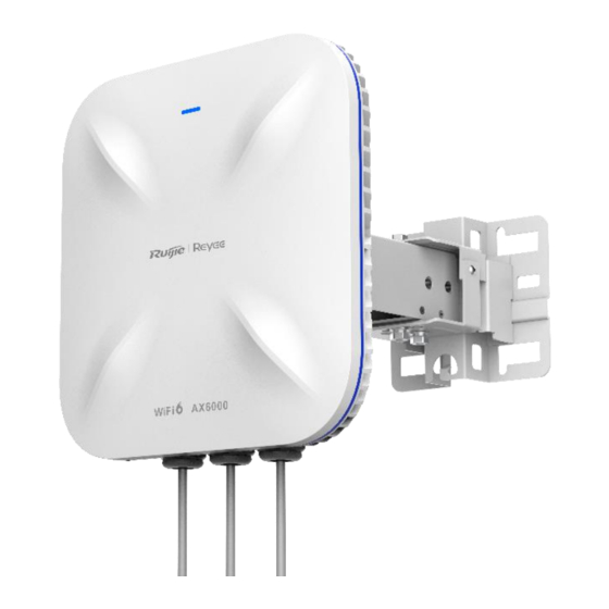
Hardware Installation and Reference Guide Product Overview Product Overview About the RG-RAP6260(H)-D Access Point The RG-RAP6260(H)-D is a dual-radio access point designed to cover a medium or large outdoor area. Compliant with the IEEE 802.11a/b/g/n/ac/ax standard, the access point can work at the 2.4 GHz and 5 GHz bands at the same time and supports quad-stream MU-MIMO. -
Page 9: Hardware Features
Hardware Installation and Reference Guide Product Overview Item Quantity Grounding Cable Note The package contents generally contain the above items. The actual delivery is subject to the order contract. And please check your goods carefully against the order contract. If you have any questions, please contact the distributor. -
Page 10: Ports And Led
Hardware Installation and Reference Guide Product Overview Ports and LED Figure 1-2 Ports Table 1-2 Ports Ports Description DC Connector 48 V DC/1 A input Ethernet/PoE 100/1000/2500Base-T Ethernet ports, PoE-capable Port The Reset hole is near the Ethernet/PoE port. Stick the pin to the Reset hole: Restart the access point. Reset Hole Press and hold the pin to the Reset hole for more than 5 seconds: Restore the access point to factory settings. -
Page 11: Reset Hole
RG-RAP6260(H)-D supports cloud-based management. To reset the access point, you are advised to connect the access point to the Internet and perform reset on Ruijie Cloud. If it is inconvenient to connect to the Internet, insert a pin into the Reset hole as marked by red point. Press... -
Page 12: Technical Specifications
Hardware Installation and Reference Guide Product Overview Figure 1-4 Reset Hole Warning You are advised to loosen the cable gland before using the Reset hole. Please see Installing the Ethernet Cable for details. Technical Specifications Table 1-4 Technical Specifications Radio Design Dual-radio, four spatial streams Standard &... - Page 13 Hardware Installation and Reference Guide Product Overview Max. Data Rate 2.4 GHz: 1148 Mbps 5 GHz: 4804 Mbps Combined: 5952 Mbps Modulation OFDM: BPSK@6/9 Mbps, QPSK@12/18 Mbps, 16QAM@24 Mbps, 64QAM@48/54 Mbps DSSS: DBPSK@1 Mbps, DQPSK@2 Mbps, and CCK@5.5/11 Mbps MIMO-OFDM: BPSK, QPSK, 16QAM, 64QAM, 256QAM and 1024QAM OFDMA 11b: –96 dBm (1 Mbps), –93 dBm (5 Mbps), –89 dBm (11 Mbps) Receiver...
-
Page 14: Power Specifications
Hardware Installation and Reference Guide Product Overview Standard PoE: IEEE 802.3bt standard (PoE++), backward compatible with the IEEE 802.3at standard (PoE+), with a data rate up to 574 Mbps in the 2.4 GHz band and 2402 Mbps in the 5 GHz band. 60 W Passive PoE adapter (Optional accessory) Local power supply: 48 V DC /1 A Note: The access point is not 802.3af-compliant. -
Page 15: Heat Dissipation
Hardware Installation and Reference Guide Product Overview Table 1-5 Power Supply Mode Power Input Standard PoE: IEEE 802.3bt standard, backward compatible with the IEEE 802.3at standard Local power supply: 48 V DC/1 A Max. Power Power Supply Mode 2.4 GHz 5 GHz Data Rate Consumption... -
Page 16: Preparing For Installation
Hardware Installation and Reference Guide Preparing for Installation Preparing for Installation Safety Precautions Note To avoid personal injury and device damage, carefully read the safety precautions before you install the access point. The following safety precautions may not cover all possible hazardous situations. General Safety Precautions ... -
Page 17: Laser Safety
Hardware Installation and Reference Guide Preparing for Installation in case of accidents. Check the access point carefully before shutting down the power supply. Keep the access point far away from grounding or lightning protection devices for power device. ... -
Page 18: Waterproof Requirement
Hardware Installation and Reference Guide Preparing for Installation Table 2-1 Working Environment Requirements Operating Temperature Operating Humidity -40° C to 65° C (-40° F to 149° F) 0% to 100% RH (non-condensing) Waterproof Requirement Seal the unused ports using the connector plugs or cable glands to ensure that the access point is watertight. ... -
Page 19: Installing The Access Point
Hardware Installation and Reference Guide Installing the Access Point Installing the Access Point Caution Before installing the access point, make sure you have carefully read the requirements in Chapter 2. Installation Flowchart Start Prepare for Installation Wall Pole Site? Installing a Mounting Plate Installing a Mounting Plate Assembly on a Pole Assembly on a Wall... -
Page 20: Precautions
Hardware Installation and Reference Guide Installing the Access Point The customized access point meets the client-specific requirements. Precautions The outdoor access point can be mounted on a wall or a pole with a diameter ranging from 50 mm to 70 mm (1.97 in. -
Page 21: Installing The Mounting Arm
Hardware Installation and Reference Guide Installing the Access Point Figure 3-2 Dimensions of Mounting Plate Assembly Installing the Mounting Arm (1) Unfasten the four screws on the bottom and keep them handy. (2) Wedge the mounting arm into the slot in the orientation noted by the arrow. -
Page 22: Wall Mounting
Hardware Installation and Reference Guide Installing the Access Point (3) Tighten the four screws using a Philips screwdriver. Wall Mounting Use the mounting plate assembly and M8 × 60 expansion anchors to install the access point. (1) Drill four holes with a hole pattern of 65 mm x 110 mm (2.56 in. x 4.33 in.) on the wall. Figure 3-3 Drilling Four Holes on Wall Drill four holes... -
Page 23: Vertical Pole Mounting
Hardware Installation and Reference Guide Installing the Access Point Figure 3-4 Securing Mounting Plate Assembly on Wall (3) Secure the access point with the mounting arm to the mounting plate assembly. Drive M8 x 20 mm screws into the holes noted by ②. Figure 3-5 Mounting Access Point Vertical Pole Mounting... -
Page 24: Horizontal Pole Mounting
Hardware Installation and Reference Guide Installing the Access Point Figure 3-6 Securing Mounting Plate Assembly on Vertical Pole (2) Secure the access point with the mounting arm to the mounting plate assembly. Drive M8 x 20 mm screws into the holes noted by ②. Figure 3-7 Mounting Access Point Horizontal Pole Mounting... -
Page 25: Adjusting Orientation
Hardware Installation and Reference Guide Installing the Access Point Figure 3-8 Securing Mounting Plate on Horizontal Pole (2) Secure the access point with the mounting arm to the mounting plate assembly. Drive M8 x 20 mm screws into the holes noted by ②. Figure 3-9 Mounting Access Point Adjusting Orientation... - Page 26 Hardware Installation and Reference Guide Installing the Access Point Adjusting down-tilt and up-tilt angles The access point allows for down-tilt and up-tilt angles of 0° , 25° , 50° and 90° . After orienting the access point to the desired angle, drive M8 x 20 mm screws into the holes noted by ④. Caution ...
-
Page 27: Installing The Cable
Hardware Installation and Reference Guide Installing the Access Point Please make sure the access point is secured in case of falling down. Installing the Cable Installing the Ethernet Cable (1) A cable gland assembly includes four components: A (adapter base), B (split gasket), C (grommet), D (compression cap). -
Page 28: Bundling Cables
Hardware Installation and Reference Guide Installing the Access Point Bundling Cables Precautions The power cords and other cables should be bound in a visually pleasing way. When you bundle twisted pairs or fiber-optic cables, make sure that the cables at the connectors have natural bends or bends of large radius. -
Page 29: Verifying Operating Status
Hardware Installation and Reference Guide Verifying Operating Status Verifying Operating Status Setting up Configuration Environment The access point can be powered by PoE or local power adapter. Verify that the power cord is properly connected and compliant with safety requirements. ... -
Page 30: Monitoring And Maintenance
Hardware Installation and Reference Guide Monitoring and Maintenance Monitoring and Maintenance Monitoring You can observe the LED color to monitor the access point status. Hardware Maintenance If the hardware is faulty, please contact technical support. -
Page 31: Common Troubleshooting
Check whether the power supply is properly connected. Check whether the LED is normal. Check whether cables are properly connected with ports. Contact Ruijie technical support to check whether hardware faults exist. Finish Common Faults Why is the LED off after the access point is powered on? ○... -
Page 32: Appendix
Hardware Installation and Reference Guide Appendix Appendix Connectors and Media 2500BASE-T/1000BASE-T/100BASE-TX Port 2500BASE-T/1000BASE-T/100BASE-TX is a 100/1000/2500 Mbps port that supports auto-negotiation and auto MDI/MDIX Crossover. Compliant with IEEE 802.3bz, 2500BASE-T requires Category 6 or Category 5e 100-ohm UTP or STP (STP is recommended) with a maximum distance of 100 meters (328.08 feet). -
Page 33: Fiber-Optic Cable Connection
Hardware Installation and Reference Guide Appendix Input Receive Data- Output Transmit Data- Output Transmit Data+ Input Receive Data+ Output Transmit Data- Input Receive Data- 4, 5, 7, 8 Not Used Not Used The following figure shows feasible connections of the straight-through and crossover twisted pairs for a 100BASE- TX port. -
Page 34: Mini-Gbic Modules
Hardware Installation and Reference Guide Appendix Mini-GBIC Modules We provide different GE SFP transceivers (Mini-GBIC modules). You can select a model to suit your specific needs. Table 7-2 Mini-GBIC Modules Core Mini- Max Tx Max Rx Fiber Cable Size GBIC (MHz Intensity Sensitivity... - Page 35 Hardware Installation and Reference Guide Appendix LH40 MINI- –20 GBIC- 50 km ZX50 MINI- –20 GBIC- 80 km 1550 ZX80 MINI- GBIC- –9 100 km ZX10 Mini- GBIC- 100 m WL: Wave Length MBW: Modal Bandwidth STD: Standard Warning For Mini-GBIC modules with a cabling distance of over 40 km (including 40 km), install an attenuator to avoid overload when using short single-mode fiber-optic cables.
-
Page 36: Cabling
Hardware Installation and Reference Guide Appendix Cabling During installation, route cable bundles upward or downward along the sides of the rack depending on the actual situation in the equipment room. All cable connectors used for transit should be placed at the bottom of the cabinet rather than be exposed outside of the cabinet. - Page 37 Hardware Installation and Reference Guide Appendix After bundling up cables with cable ties, cut off the remaining part. The cut should be smooth and trim, without sharp corners. Figure 7-5 Binding Cables When cables need to be bent, please bundle them up but do not tie them where the cables will be bent. When cables need to be bent, please bundle them up but do not tie them where the cables will be bent.
- Page 38 Hardware Installation and Reference Guide Appendix Figure 7-7 Cable Fastening Flat Washer Spring Washer Flat Washer Hard power cords should be fastened in the terminal connection area to prevent stress on terminal connection and cable. Do not use self-tapping screws to fasten terminals. ...
Need help?
Do you have a question about the Reyee RAP6260-D and is the answer not in the manual?
Questions and answers