Table of Contents
Advertisement
Advertisement
Table of Contents

Related Manuals for Ruijie RG-AP720-I


Summary of Contents for Ruijie RG-AP720-I
- Page 1 RG-AP720-I Access Point Quick Installation Guide...
- Page 2 This document is provided “as is”. The contents of this document are subject to change without any notice. Please obtain the latest information through the Ruijie Networks website. Ruijie Networks endeavors to ensure content accuracy and will not shoulder any responsibility for losses and damages caused due to content omissions, inaccuracies or errors.
- Page 3 It is intended for the users who have some experience in installing and maintaining network hardware. At the same time, it is assumed that the users are already familiar with the related terms and concepts. Obtaining Technical Assistance Ruijie Networks Website: http://www.ruijienetworks.com/ Service Email: service_rj@ruijienetworks.com ...
-
Page 4: Packing List
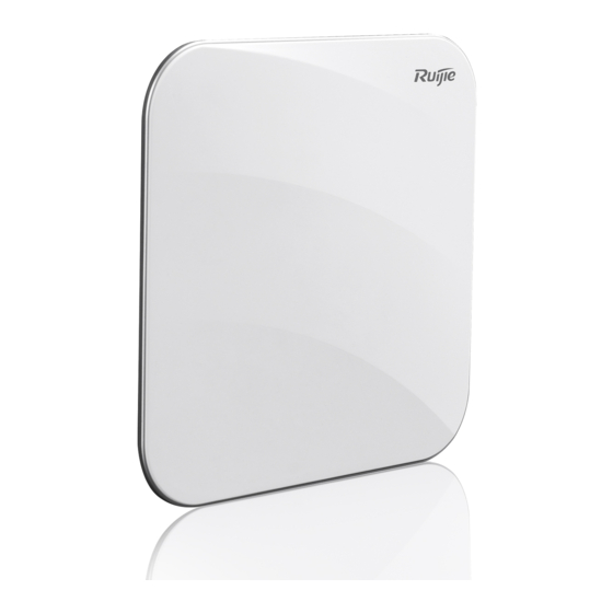
1 Packing List Table 1-1 Packing List Item Name Quantity Unit RG-AP720-I Host RG-AP720-I Plate Cover (White) Piece RG-AP720-I Access Point Quick Installation Guide Copy Product Warranty Copy Cross Recessed Pan Head Tapping Screw and Washer Piece Assemblies Anchors Piece... - Page 5 2 Product Image Figure 2-1 Product Image of RG-AP720-I Figure 2-2 Top View of RG-AP720-I Figure 2-3 Bottom View of RG-AP720-I...
- Page 6 ① Built-in indicator Note: ② Reset hole ③ USB port ④ Console port ⑤ LAN2 port ⑥ LAN1/PoE port ⑦ 48VDC power input...
- Page 7 The LED indicator is on the top plate, and works after you power on the device. You can also configure the Silent time on the AC/AP. Table 3-1 Button and LED Indicators on RG-AP720-I in the Fit mode State Frequency Meaning The AP is powered off.
- Page 8 4 Installing RG-AP720-I Ceiling Mount Drill four 6 mm diameter holes (53 mm apart) on the ceiling. Tap wall anchors into the holes, and drive screws through the mounting bracket into the anchors to fix the bracket. Figure 4-1 Attaching the Mounting Bracket on the Ceiling Align the square feet on the bottom of the AP with the mounting holes on the bracket.
- Page 9 The AP can be installed in any of four directions on the mounting bracket depending on how you route your Ethernet cables. The square feet should fit easily into the mounting slots. Do not forcibly push the AP into place. After installation, verify that the AP is securely fastened.
- Page 10 Before mounting the AP on the bracket, you must first connect the Ethernet cables. Slide the AP into the holes in the direction against the arrow on the mounting bracket until it clicks into place. Note that “Ruijie” logo is on the upside. Figure 4-6 Mounting the AP on the Bracket ...
- Page 11 Align the square feet on the rear of the AP with the mounting holes on the bracket, slide the AP in the direction against the arrow on the mounting bracket until it clicks into place. Figure 4-8 Mounting the AP on the Bracket ...
- Page 12 If the AP is installed on the ceiling, hold the AP with both of your hands and push it in different directions as shown in figure 4-11 until the AP is separated from the bracket (the AP can be removed only in one direction). Figure 4-11 Removing the Ceiling-Mount AP...
-
Page 13: Quick Configuration
5 Quick Configuration Step 1: Navigate to the Web login page. In the Fit mode, the IP address of the LAN1 port and the LAN2 port are 192.168.110.1/24. In the Fat mode, the IP address of the LAN1 port is 192.168.110.1/24, and the IP address of the LAN2 port is 192.168.111.1/24. - Page 14 Click FAT AP Mode on the right panel to switch the AP over to the FAT mode. Click the button to perform quick configuration. The AP can work in AP access mode or wireless routing mode. 1 ) Select AP Access Mode. Configure the VLAN and IP address, and click Next.
- Page 15 Enter the SSID and WiFi password, and click Finish to finish the configuration.
- Page 16 2 ) Select Wireless Routing Mode. Select an Internet connection type, enter related parameters, and click Next.
- Page 17 Enter the SSID and WiFi password, and click Finish to finish the configuration.
Need help?
Do you have a question about the RG-AP720-I and is the answer not in the manual?
Questions and answers