Table of Contents
Advertisement
Quick Links
Tempest Commercial Treadmill
Read all instructions carefully before using this product.
Retain this owner's manual for future reference.
IMPORTANT
All nuts and bolts are to be checked and tightened on a regular basis. This includes pedals and
other moving parts. Failure to do so may cause damage to your threads and void your warranty.
NOTE:
Product may vary slightly from the item pictured due to model upgrades. This manual may be subject to updates or changes.
Up to date manuals are available through our website at www.lifespanfitness.com.au
USER MANUAL
Advertisement
Table of Contents

Related Manuals for LifeSpan TEMPEST CR


Summary of Contents for LifeSpan TEMPEST CR
- Page 1 Tempest Commercial Treadmill USER MANUAL Read all instructions carefully before using this product. Retain this owner’s manual for future reference. IMPORTANT All nuts and bolts are to be checked and tightened on a regular basis. This includes pedals and other moving parts. Failure to do so may cause damage to your threads and void your warranty. NOTE: Product may vary slightly from the item pictured due to model upgrades.
-
Page 2: Table Of Contents
TABLE OF CONTENTS Important Safety Instructions ....... 03 II. Important Electrical Information ......05 III. -
Page 3: Important Safety Instructions
I. IMPORTANT SAFETY INSTRUCTIONS WARNING: Read all instructions before using this treadmill. It is important your treadmill receives regular maintenance to prolong its useful life. Failing to regularly maintain your treadmill may void your warranty. DANGER To reduce the risk of electric shock disconnect your treadmill from the electrical outlet prior to cleaning and/or service work. - Page 4 • The treadmill is intended for in-home use only and is not suitable for commercial environments. • To disconnect, turn all controls to the off position, remove the safety key, and then remove the plug from the outlet. • The pulse sensors are not medical devices. Various factors, including the user’s movement, may affect the accuracy of heart rate readings.
-
Page 5: Important Electrical Information
II. IMPORTANT ELECTRICAL INFORMATION WARNING! This treadmill requires the right power source in order to properly operate. For your safety, as well as the safety of others, please verify that the power source is correct before plugging the equipment. Any incorrect power source could cause significant damage to the equipment and/or user. -
Page 6: Important Operating Instructions
III. IMPORTANT OPERATING INSTRUCTIONS • Understand that changes in speed and incline do not occur immediately. Set your desired speed on the computer console and release the adjustment key. The computer will obey the command gradually. • Use caution while participating in other activities while walking on your treadmill, such as watching television, reading, etc. -
Page 7: Assembly Instructions
IV. ASSEMBLY INSTRUCTIONS PARTS LIST Description Description Main Frame Console Left Upright Tube Power Wire Right Upright Tube Silicon Oil Console Frame B08 6# (x1) B09 8# (x1) B10 6*125 (x1) B11 19# (x1) D31 Ø8 (x4) D32 Ø10 (x12) D06 M10*20 (x12) D12 M8*15 (x4) D33 Ø10 (x12) - Page 8 STEP 1 Open the carton and remove the contents. Place the Main Frame on level ground, ensure that you have a work area that is clean and has adequate space. | ASSEMBLY INSTRUCTIONS...
- Page 9 B10 6*125 (x1) STEP 2 Loosen the Bolt (No. D16) on the Motor top cover (No. C01) by using Cross screwdriver (No. B10). Set aside the cover and the screws for re-installation later. ASSEMBLY INSTRUCTIONS |...
- Page 10 B09 8# (x1) D06 M10*20 (x6) D32 Ø10 (x6) D33 Ø10 (x6) STEP 3 1. Connect the wire from Right upright tube (No. C) (E07) and Main base (No. A) (E08) as pictured. 2. Support the Left & Right Upright Tubes (No. B & No. C) with your hands to prevent them from falling. 3.
- Page 11 B09 8# (x1) D06 M10*20 (x6) D32 Ø10 (x6) D33 Ø10 (x6) STEP 4 1. Connect the wire from Right upright tube (No. C) (E07) and Console base (No. D) (E06). 2. Attach the Left & Right Upright Tubes (No. B & No. C) to the Console base (No. D) by using 6x Bolts (No.
- Page 12 B10 6*125 (x1) D16 M5*12 (x5) STEP 5 1. Attach the Bolt (No. D16) to the Motor top cover (No. C01) by using Cross screwdriver (No. B10). 2. Put out the Console screw cover (No. C19) from underneath the Console base (No. D). | ASSEMBLY INSTRUCTIONS...
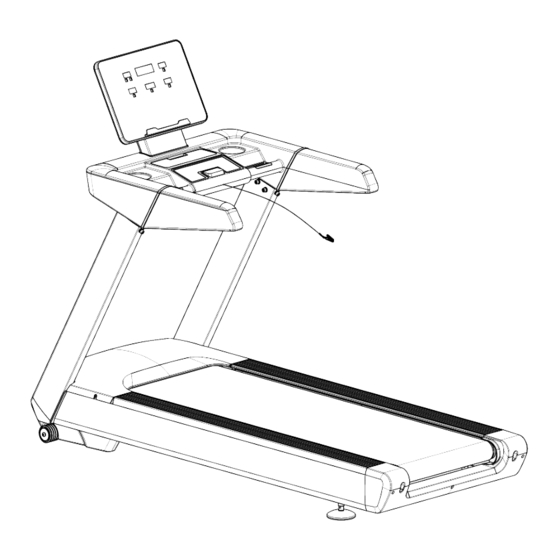
- Page 13 B08 6# (x1) D12 M8*15 (x4) D31 Ø8 (x4) D34 Ø8 (x4) STEP 6 Attach the Console (No. E) to the Console base (No. D) by using 4x Bolts (No. D12), 4x Washers (No. D31) and 4x Washers (No. D34). Secure by using #6 Allen Wrench (No. B08). ASSEMBLY INSTRUCTIONS |...
- Page 14 STEP 7 1. Connect the wire as above. 2. B. Attach the Console screw cover (No. C19) back to the Console base (No. D). The assembly is complete! | ASSEMBLY INSTRUCTIONS...
- Page 15 STEP 8 Connect the power cord to the back of the machine and plug to the wall socket. We don’t recommend plugging on a Power board with other equipment as this is a high-powered equipment. Turn on the power and you can begin workout. When not in use, you can turn off the power from the back switch or the wall switch.
-
Page 16: How To Move The Treadmill
V. HOW TO MOVE THE TREADMILL Transportation wheels are at the front of the machine and will need to be lifted from the back of the treadmill and tilted onto the wheels. The machine is heavy and may require 2 persons. Ensure to seek help if needed. | HOW TO MOVE THE TREADMILL... -
Page 17: Operation Guide
VI. OPERATION GUIDE BUTTON FUNCTIONS: 1. INCLINE -: Press this button to reduce the incline. 2. INCLINE +: Shows speed and program. 3. INSTANT INCLINE: Press 3, 6, 9 for quick incline adjustment. 4. START: Press this button to start the machine. 5. - Page 18 MEDIA HUB: 1. MP3 INPUT: Insert MP3 cable to display the music from device. 2. USB INPUT: Charging your device. COMPUTER FUNCTIONS: 1. INCLINE: Displays current incline. Press INCLINE+/- to adjust the incline of the machine. 2. SPEED: Displays current speed. Press SPEED+/- to adjust the speed of the machine. 3.
- Page 19 - You can still press SPEED+/- or INCLINE+/- to change the speed and incline during each program. - Once the program is completed it will beep 3 times. - Press the START button, treadmill will run after 3 seconds. - Press SPEED+/- to adjust the speed. - Press INCLINE+/- to adjust the incline.
-
Page 20: Exercise Guide
VII. EXERCISE GUIDE PLEASE NOTE: Before beginning any exercise program, consult your physician. This is important especially for individuals over the age of 45 or with pre-existing health problems. The pulse sensors are not medical devices. Various factors, including the user’s movement, may affect the accuracy of heart rate readings. - Page 21 COOL DOWN Finish each workout with a light jog or walk for at least 1 minute. Then complete 5 to 10 minutes of stretching to cool down. This will increase the flexibility of your muscles and will help prevent post- exercise problems.
-
Page 22: Maintenance Instructions
VIII. MAINTENANCE INSTRUCTIONS General cleaning will help prolong the life and performance of your treadmill. Keep the unit clean and maintain it by dusting the components on a regular basis. Clean both sides of the running belt to prevent dust from accumulating underneath the belt. Keep your running shoes clean so that dirt from your shoes does not wear out the running board and belt. - Page 23 2. The moving parts should turn freely and quietly. Abnormality of moving parts will affect the safety of the equipment. Inspect and tighten bolts regularly. 3. To better maintain the treadmill and prolong its lifespan, it is suggested that maintenance be done on a regular basis.
-
Page 24: Exploded Diagram
IX. EXPLODED DIAGRAM | EXPLODED DIAGRAM... - Page 25 EXPLODED DIAGRAM |...
-
Page 26: Parts List
X. PARTS LIST Key No. Description Qty. Key No. Description Qty. Motor Right Side Main Frame Cover Incline Bracket Left Side Rail Console Base Decoration Bracket Right Side Rail Left Upright Tube Decoration Right Upright Tube Top Side Rail Panel Connecting Left Side Rail Bracket Right Side Rail... - Page 27 Key No. Description Qty. Key No. Description Qty. Cushion Screw ST4.2*25 Square Tube Plug Screw ST2.9*8 Plastic Gasket Screw ST4.2*12 Cylindrical Screw ST4.2*12 Cushion Screw ST2.9*8 Running Belt Lock Washer Motor Belt Lock Washer Left Handlebar Lock Washer Decorative Ring Spring Washer Right Handlebar Decorative Ring...
- Page 28 Key No. Description Qty. Key No. Description Qty. Hand Pulse Bottom Power Wire Signal Wire AC Signal Wire 200 Brown Microswitch AC Signal Wire 350 Brown Switch Top Signal AC Signal Wire 350 Blue Wire Magnetic Ring Switch Bottom Signal Wire Magnetic Core Safety Key Ground Wire...
- Page 29 TROUBLESHOOTING Issue Solution Computer not turning on after 1. Please check if the overload protect jump, if yes, please plugging to power press it, let it continue to work. 2. Check if the wires of power switch, overload protect, control board and the transformer are connected properly. 3.
- Page 30 Issue Solution Display E08 The inverter can not receive signal from board: 1. The communication between the inverter and the display is blocked. Check every connection between the display and the inverter communication cable to ensure that each wire core is fully inserted; Check if the connection wire between the display and the inverter is damaged, and replace the communication connection wire.
-
Page 31: Warranty
Any claim against this warranty must be made through your original place of purchase. Proof of purchase is required before a warranty claim may be processed. If you have purchased this product from the Official Lifespan Fitness website, please visit https://lifespanfitness.com.au/warranty-form For support outside of warranty, if you wish to purchase replacement parts or request a repair or service, please visit https://lifespanfitness.com.au/warranty-form and fill in our Repair/Service... - Page 32 WWW.L IF ESPAN F ITNE S S . COM . A U...
Need help?
Do you have a question about the TEMPEST CR and is the answer not in the manual?
Questions and answers