
Related Manuals for Lissmac LWSE 540


Summary of Contents for Lissmac LWSE 540
- Page 1 OPERATING MANUAL Electric wall saw LWSE 540 LISSMAC Maschinenbau GmbH Lanzstrasse 4 D-88410 Bad Wurzach, Germany Phone +49 (0) 7564 / 307-0 Fax +49 (0) 7564 / 307-500 lissmac@lissmac.com www.lissmac.com 1/50...
- Page 2 2/50...
- Page 3 Imprint This operating manual is for: LISSMAC wall saw • LWSE 540 Manufacturer: LISSMAC Maschinenbau GmbH Lanzstraße 4 D - 88410 Bad Wurzach, Germany Phone: +49 (0) 7564 / 307 – 0 Fax: +49 (0) 7564 / 307 – 500 lissmac@lissmac.com...
- Page 4 GENERAL SAFETY NOTES Warning notices and symbols in this manual SIGNAL WORD Type and source of the hazard Consequences of non-compliance Action to avert the hazard The signal word behind the hazard symbol indicates the hazard level: DANGER This signal word indicates an extremely dangerous situation. If the situation is not avoided, it will result in fatal injuries.
- Page 5 The following warning and safety notices are used: Read the operating manual Wear ear protectors Wear safety goggles Wear gloves Wear a protective helmet Wear a dust protection mask Wear suitable work clothes and wash dusty clothes Wear safety shoes Remove the power plug before working on the machine Dangerous electrical voltage Danger of cuts and amputation through rotary cutting tools...
- Page 6 OPERATING MANUAL Preface This operating manual shall make it easier to become acquainted with the machine and to make full use of it as intended. The operating manual contains important information on how to operate the machine safely, properly and economically. Following it will help to prevent danger, avoid repair costs and downtimes, and increase the reliability and service life of the machine.
- Page 7 Notes: 7/50...
-
Page 8: Table Of Contents
Table of contents 1. Properties & advantages ....................9 2. General safety information .................... 10 2.1. Intended use policy ......................10 2.2. Organizational measures ....................11 2.3. Choice of personnel, qualifications; fundamental obligations ........12 2.4. Safety notices regarding the operating phases .............. 12 2.4.1. -
Page 9: Table Of Contents 1. Properties & Advantages
1. PROPERTIES & ADVANTAGES Simple, safe operation · Perfect straight cut · Adjustable cutting depth · Low physical demands compared to handheld saws · Suitable for reinforced concrete and masonry · Extensive accessories Guide rails · Extremely light aluminum profile ·... -
Page 10: General Safety Information
Intended use The LISSMAC wall saw is exclusively intended for cutting joints or grooves in (reinforced) concrete and masonry. The saw may only be operated in conjunction with the saw guide rail. The saw may only be operated by a single person. -
Page 11: Organizational Measures
2.2. Organizational measures The operating manual must be kept within reach of every person at the place where the machine is used. Generally valid legal or other obligatory regulations for accident prevention and environmental protection constitute supplements to the operating manual; users must be informed of these and they must be observed. -
Page 12: Choice Of Personnel, Qualifications; Fundamental Obligations
2.3. Choice of personnel, qualifications; fundamental obligations Operators must be aged at least 18 and be mentally and physically capable of operating the machinery. All persons must be instructed in operation of the machinery and have been expressly tasked with operating the machine, in writing. Establish personnel responsibilities for operating, outfitting, maintenance and servicing. -
Page 13: Commissioning
2.4.2. Commissioning Only use original accessories and the tool approved by the manufacturer. Check the direction of operation when fitting the saw blade. Protect hands from sharp edges when fitting the saw blade. Blade may be hot after cutting. Wear gloves to change it. Ensure that the ground/floor has adequate load-bearing capacity. -
Page 14: Repositioning The Saw
Every person who enters the working area must be wearing personal protective equipment. The machine may not be operated in areas where there are explosive risks. Avoid bodily contact with earthed surfaces such as heating pipes, in order to minimize the risk of electrocution. -
Page 15: Notice On Specific Hazard Categories
2.5. Notice on specific hazard categories 2.5.1. Electrical energy Only use original fuses with the specified amperage. If a fault occurs, the machine must be switched off immediately! Electrical work may only be carried out by certified qualified experts. The machine’s electrical equipment must be inspected and tested at regular intervals. Defects, such as loose connections or damaged cables, must be corrected immediately. -
Page 16: Packaging And Storage
2.6. Packaging and storage In order to ensure sufficient protection during dispatch and transport, the machine and its components have been carefully packed. On receipt of the machine, it should be checked for damage. The device packaging consists of recyclable materials. Please place these into the appropriate collection containers, so that they can go for recycling. -
Page 17: Device Description
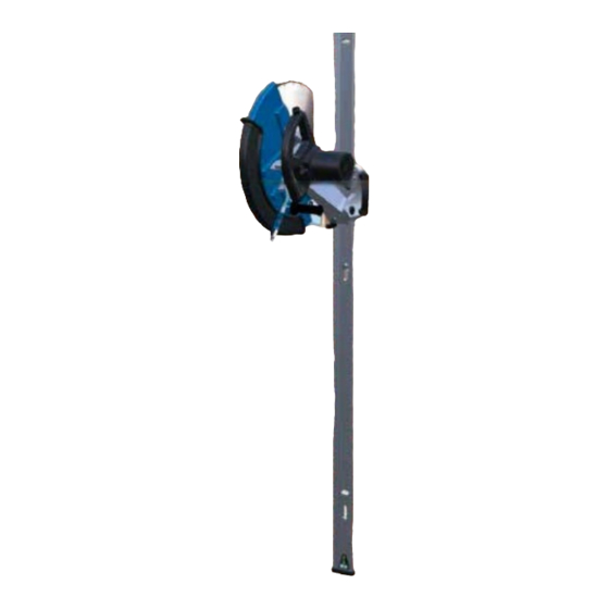
3. DEVICE DESCRIPTION 3.1. Machine part names 17/50... - Page 18 Item 1 Blade guard with gripping surface Item 11 Guide rail Item 2 Water connection with shut-off valve Item 12 Levels Item 3 On/off switch Item 13 End cap Item 4 Handle Item 14 Anchor bolts Item 5 Electric motor Item 15 Adjusting plates Item 6...
-
Page 19: Technical Data
3.2. Technical data LWSE 540 Saw blade diameter 350 mm 450 mm 540 mm Saw blade width 3 mm 2.8 mm 2.6 mm Max. cutting depth 110 mm 165 mm 210 mm Max blade clamp Ø 30 mm Saw shaft rpm... -
Page 20: Hand-Arm Vibration
The specified value was determined with the maximum saw blade diameter of 1000 mm. The effects can be inversely proportional to the weight of the operator. Vibration total value: LWSE 540 a less than 2.5 m/s The following standards were observed during measurement: EN ISO 5349, VD 2057 Sheet 2, Directive 2002/42/EC. -
Page 21: Commissioning
4. COMMISSIONING 4.1. Tools (saw blade) NOTICE Rotary tools with a maximum speed less than the nominal speed of the machine may not be used. Defective or cracked tools must be replaced immediately. Selecting the saw blade Storing tools The tools used must be protected from moisture. The segments installed around the saw band must be protected from damage. -
Page 22: Tool (Saw Blade) Installation / Replacement
4.2. Tool (saw blade) installation / replacement WARNING Cuts and entanglement hazard from the rotating tool The rotating tool can cause cuts, severed limbs and burning. It is forbidden to remove or open the saw blade guard, or to reach into the rotating saw blade ... -
Page 23: Operation
5. OPERATION 5.1. Safety Clarify the situation Before cutting, obtain the permission of the site manager and clarify the following important points: Are the cuts structurally harmless? WARNING Danger of collapse! Do pipes (water/heating/gas) or cables (electricity/data) run through the wall/ceiling/floor? WARNING Danger of burst pipe/cable leading to damages, gas explosion, electrocution and fire How large may the blocks to be cut out be (dimensions and weight for removal)? - Page 24 DANGER Danger of collapse due to damaged structure Serious or fatal injury from falling masonry if load-bearing structures are weakened or severed. Check that the ground is suited for affixing Anchor the machine correctly Secure cut segments against falling ...
-
Page 25: Secure Hazard Zones
5.2. Secure hazard zones Mark cuts Measure cuts and establish safety zone. Secure hazard zone Secure front AND back of the cut Take especial care to secure against falling dangers when cutting floors or ceiling. Establish a safety distance of at least 1.5 m, on both sides of the cut. 5.3. -
Page 26: Fit Rails
5.4. Fit rails Mount guide rails Ensure secure anchorage. Only use the recommended plugs and install according to the manufacturer’s instructions. If necessary, install a spray guard for the area surrounding the cut. 26/50... - Page 27 Adjust for any unevenness with suitable underlay. Rails must not bend or warp! 27/50...
-
Page 28: Mounting And Operating The Saw
5.5. Mounting and operating the saw WARNING Electrocution hazard Danger of serious injuries from electrocution if water penetrates into the device. Engine must never be mounted beneath water supply in drip range Engine position Cutting Stick to the cutting sequence. Blade must not be jammed by the blocks that are cut out When cutting, take care to cut right-angled cuts, or deliberately tapered cuts respecting the extraction... -
Page 29: Mounting The Saw Blade
5.6. Mounting the saw blade Saw blade for mounting (pre-cut) 29/50... -
Page 30: Mount Wall Saw On Rails
5.7. Mount wall saw on rails Mount wall saw Put the brakes on the carriage and affix saw securely in the rail guide. Never mount the wall saw backwards. Handles are always on the same side. 30/50... -
Page 31: Supply And Extraction
5.8. Supply and extraction Install extractor Prepare extractor for slurry or dust and test functionality Establish water supply Water supply 5 bar max. In heavy frost conditions, antifreeze must be added, and the water should be drained during prolonged work interruptions. -
Page 32: Guide Cut And Depth Stop
5.10. Guide cut and depth stop Guide cut A pre-cut increases the accuracy of the cut. Configuring the depth stop sets the cut depth. Configure depth stop 32/50... -
Page 33: Cutting
Guide cut The cut depth should be no more than 10 % of the saw blade diameter. Cut with repeated passes using increasingly large blades until the desired depth or breakthrough is achieved. 5.11. Cutting Cutting through CAUTION No longitudinal cuts in reinforcement bars! Reinforcement must always be cut all the way reinforcement through by the tool. -
Page 34: Changing The Blade For Depth Cut
5.12. Changing the blade for depth cut Deepen cut Mount larger blades to bring the cut to the desired depth. 5.13. Block removal Block removal During removal, be aware of the load on the floor. Don’t drop blocks! Tip blocks onto car tires on the ground. Remove higher blocks using a lift system. -
Page 35: Secure Construction Site
5.14. Secure construction site Close off or seal areas of floor or external walls where segments have been removed. Determine X according to national regulations. 5.15. Slurry / dust removal Remove slurry and dust in accordance with local regulations and in an environmentally friendly manner. Recommended procedure: •... -
Page 36: Accessories (Optional)
5.17. Accessories (optional) Wall-flush cut The machine can be fitted with an optional blade guard and flanges for wall-flush cuts. The machine must be suitably modified for this purpose. #1043663 Cutting without a blade guard is not permitted! Rail connector Rail connectors can be used to extend the saw run. -
Page 37: Servicing
6. SERVICING 6.1. Maintenance WARNING Danger of injury from rotating parts Serious injury from rotating saw blade or belt drive. Maintenance and repairs may only take place when the machine is switched off Maintenance and repairs may only be carried out by trained personnel. The machine must be secured against anyone else switching it on. - Page 38 6.2. Replace bushing If the bushings are worn out, they can be replaced as follows: 38/50...
-
Page 39: Fault Lookup Table
6.3. Fault lookup table Measures have to be taken so that it is not possible for others to inadvertently restart the machine! Maintenance and service work may only be carried out by qualified experts! NOTICE If cutting problems occur, the following points must be checked first: ... -
Page 40: Maintenance Schedule
6.4. Maintenance schedule This section is intended to serve as evidence of maintenance work carried out and service log book. All maintenance work and services must be logged as evidence. Machine/type: Serial number/year of manufacture: Date Maintenance work or servicing completed Date/signature 40/50... -
Page 41: Warranty
7. WARRANTY The warranty for this machine is 12 months. For the wear parts listed below, the warranty is only valid for wear that is not due to operation. Wear parts are those parts that are subject to operational wear when the machine is used as intended. The wear time cannot be defined in a uniform manner, it differs according to the usage intensity. -
Page 42: Replacement Part List
8. REPLACEMENT PART LIST 42/50... - Page 43 Item Part No. Name Specification Recommended spare part O-Ring Quad ring Gardena adapter G 1/4“ Cover Valve Flow regulator 1/4“ Hexagon screw Hexagon socket screw Washer Washer Washer Countersunk screw Handle Water pipe Flow display blue Screw fine-threaded 10.9 Engine Blade guard 540 mm Blade guard 540 mm incl.
- Page 44 44/50...
- Page 45 Item Part No. Name Specification Recommended spare part Hexagon socket screw Countersunk screw End stop Rail 1.3 m Rail 2.3 m Levels Needle bearing Handle Cylinder head screw Cylinder head screw Thread insert Spring retaining ring Safety washer Axle 1079046 Sliding foil Sliding block Carriage...
- Page 46 46/50...
- Page 47 Item Part No. Name Specification Recommended spare part 1088058 Stator Isolation ring Ball-bearing Engine casing Cylinder head screw 1074477 Carbon brush 1076674 Sealing cap Combi-screw Type plate Protective film Electronics Capacitor O-Ring 1015659 Ball-bearing Ventilator Fan cover 1076292 Rotor incl. 2,3 Washer Screw Screw...
- Page 48 To avoid incorrect deliveries, please specify the complete full name, year of manufacture and machine number when ordering spare parts. Technical changes reserved! We would expressly draw your attention to the fact that parts not supplied by us have also not been tested or approved by us Installation and use of such products may have a negative effect on the properties of your device and thus adversely affect its safety level.
-
Page 49: Original Ec Declaration Of Conformity
LISSMAC Maschinenbau GmbH, D-88410 Bad Wurzach, Germany Machine description: The LISSMAC wall saw is exclusively intended for cutting joints in concrete and masonry. This machine may be only be used for a dry cut if there is a suitable extraction system. Only diamond saw blades are approved, with a diameter up to 540 mm max. - Page 50 50/50...
Need help?
Do you have a question about the LWSE 540 and is the answer not in the manual?
Questions and answers