
Related Manuals for Lissmac UNICUT 600


Summary of Contents for Lissmac UNICUT 600
- Page 1 OPERATING MANUAL FLOOR SAW UNICUT 600 LISSMAC Maschinenbau GmbH Lanzstrasse 4 88410 Bad Wurzach, Germany Phone +49 (0) 7564 / 307-0 Fax +49 (0) 7564 / 307-500 lissmac@lissmac.com www.lissmac.com 1/93...
- Page 2 2/93...
- Page 3 Legal notice This operating manual is valid for: LISSMAC floor saw UNICUT 600 Manufacturer: LISSMAC Maschinenbau GmbH Lanzstrasse 4 D - 88410 Bad Wurzach Phone: +49 (0) 7564 / 307 – 0 Fax: +49 (0) 7564 / 307 – 500 lissmac@lissmac.com...
- Page 4 Instructions for the operator The warning notes contained are not exhaustive. Lissmac cannot foresee every potential hazard. Reasonable safety rules and precautions must be followed as with any other machine, in terms of working methodology and operation. 4/93...
- Page 5 Warning and safety notes used: Read the operating manual Wear hearing protection Wear safety goggles Wear work gloves Wear gloves Wear protective helmet Wear dust mask Attachment point for crane transports Remove the ignition key before working on the unit Cutting hazard at the rotating tool Wait for all parts to stop Do not relocate the machine with rotating tool...
- Page 6 Warning of toxic fumes. Warning of potential injuries due to high pressure leaks. Warning of electric shock due to damaged power lines. Warning of batteries. Explosion hazard Do not use high pressure cleaners Use by unauthorized persons not permitted No step area No Smoking Inhalation hazard Lashing point for vehicle transport...
- Page 7 In addition to this operating manual, further documentations from the respective manufacturer of individual components of the machine are available: Internal combustion engine operating manual For completeness regarding further documentation, LISSMAC does not assume responsibility or liability regarding their completeness. Changes and reservations We have taken every effort to ensure that this operating manual is correct and up to date.
- Page 8 Notes: 8/93...
-
Page 9: Table Of Contents
Table of contents 1. Features & Benefits ....................... 11 2. General safety notes ...................... 12 2.1. Principle of intended use ....................12 2.2. Organizational measures ....................13 2.3. Choice of personnel and - qualification; fundamental obligations ........14 2.4. Safety notes regarding the operating phases ..............14 2.4.1. - Page 10 8.2. Tilting the slider box ....................... 51 8.3. Off-setting the slider box ....................52 8.4. Other adjustment options ....................53 9. Maintenance ........................54 9.1. Servicing ......................... 54 9.2. Maintenance intervals ....................55 9.3. Cleaning the water pump....................56 9.4. Air filter clogged ......................57 9.5.
-
Page 11: Table Of Contents 1. Features & Benefits
All settings can be made on the central display and all engine values can be read on the display Easy access for common maintenance (air filters, oil and fuel filters) The UNICUT 600 complies with the emission regulations of US EPA Tier 4/EU category IV 11/93... -
Page 12: General Safety Notes
Intended use The LISSMAC floor saw belongs to the floor cutting grinder and is designed exclusively for cutting joints in concrete or asphalt with the help of water. The cutting includes saw blades and may only be used for cutting on the ground. -
Page 13: Organizational Measures
2.2. Organizational measures This operating manual must be kept within easy reach for everyone at the place of use. Supplements to the operating manual include general statutory and other binding regulations for preventing accidents and protecting the environment and must be obeyed. These duties may also relate, for example, to handling hazardous substances or wearing personal protective equipment or road traffic regulations. -
Page 14: Choice Of Personnel And - Qualification; Fundamental Obligations
2.3. Choice of personnel and - qualification; fundamental obligations Operators must be aged 18 or above and they must be mentally and physically capable of operating the floor saw. All persons must be instructed in the operation and be expressly assigned by the employer with the operation of the floor saw. -
Page 15: Commissioning
2.4.2. Commissioning Check the direction of rotation when fitting the saw blade. The cutting process must always be done in synchronism (pointing downwards); otherwise, the material breaks and small parts are hurled around. When fitting the saw blade, protect your hands from sharp edges. Make sure the substrate that is used for cutting meets the load-bearing capacity. -
Page 16: Relocating The Floor Saw
2.4.4. Relocating the floor saw The floor saw may only be relocated when the saw blade is stationary. Before leaving the operating position on the floor saw, the internal combustion engine must be switched off and the saw blade must be stationary. There is a risk of injury from a rotating saw blade. -
Page 17: Electrical Energy
2.5.2. Electrical energy Only use original fuses with the prescribed amperage. The floor saw must be switched off immediately in the event of faults. Electrical work may only be carried out by certified and qualified technical personnel. The electrical equipment of a machine must be inspected/checked at regular intervals. Defects such as loose connections and damage cables must be rectified immediately. -
Page 18: Packing And Storage
2.7. Packing and storage In order to ensure sufficient protection during dispatch and transport, the machine and its components were packed carefully. The machine should be checked for damage upon receipt. The machine's packaging consists of recyclable materials. Please sort them into different materials and place them in the appropriate containers so that they can be recycled. -
Page 19: Device Description
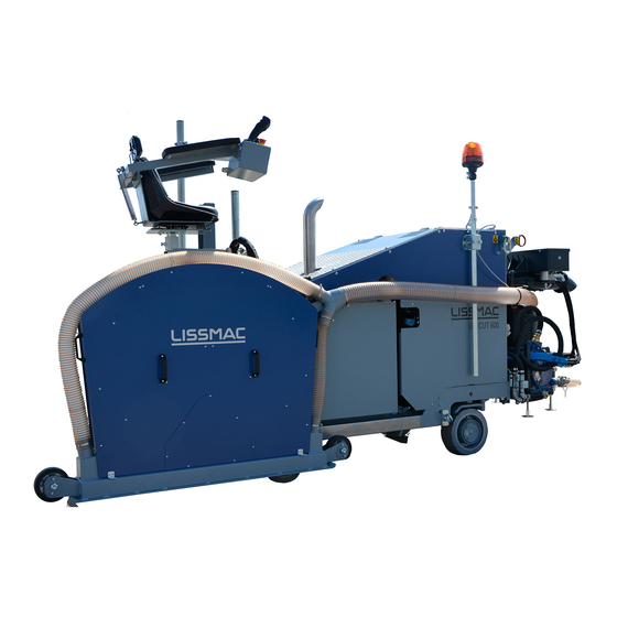
3. DEVICE DESCRIPTION 3.1. Designation of machine parts Pos. 1 Steering rod Pos. 7 Control panel Pos. 2 Blade guard Pos. 8 Driver seat Pos. 3 Suction shoe Pos. 9 Engine cover Pos. 4 Footboard Pos. 10 Exhaust pipe Pos. 5 Cutline indicator Pos. -
Page 20: Connections/Interfaces
3.2. Connections/interfaces Power Item 1 Socket water pump 12V (15A) switchable Item 2 Socket 1 12V (10A) switchable Item 3 Socket 2 12V (10A) switchable Item 4 Socket 3 12V (10A) switchable Item 5 Socket 4 12V (10A) switchable Item 6 Socket 5 12V (10A) constant current Water Item 7... -
Page 21: Technical Specifications
3.3. Technical specifications UNICUT 600 Max. cutting depth 630 mm Max. saw blade diameter 1500 mm Saw blade arbor 35 mm (6 x M12 - TK120 mm) Forward cutting motion Hydraulically stepless 0-60 m/min. Backward cutting motion Hydraulically stepless 0-60 m/min. -
Page 22: Sound Power Level
3.4. Sound power level WARNING Danger of hearing damage As from a sound power level of 85 dB (A), wearing hearing protection is mandatory. Wear your personal hearing protection. The detail defines the volume of the noise relative to the operator's workplace and to the sound power level of the floor saw. -
Page 23: Hand-Arm Vibration
3.6. Hand-Arm vibration WARNING Vibration hazard Vibration can lead to bone or joint damage as well as circulatory disorders. Take regular breaks when working with the machine The specified value was determined with the maximum saw blade diameter of 1000 mm. The impact may be inversely proportional to the weight of the operator. -
Page 24: Commissioning
4. COMMISSIONING 4.1. Connections and media Diesel (DSL) Use only diesel fuels according to EN 590 / ASTM D 975 No. 2D with a Sulphur content <15 mg/kg (so-called ULSD (Ultra Low Sulphur Diesel)). When using other fuels, the emission levels change and the warranty expires. -
Page 25: Water Pump
4.3. Water pump The removable water pump is suspended at the machine and supplies the saw blade with water. The 200l tank enables standalone operation of the machine. The water connection is via GEKA couplings. The pump has a sieve insert for daily visual inspection and cleaning. -
Page 26: Saw Blade Installation/Change (Tool)
4.5. Saw blade installation/change (tool) WARNING Risk of injury from rotating parts Rotating saw blade or flange can catch and sever clothes or body parts. Switch off the engine and remove the ignition key. Before working on the machine, all parts must be stationary. ... -
Page 27: Conversion Of Seat Position (Optional)
Sequence Unlock the guard by loosening the two locking screws (item 1). Remove blade guard upwards over the handles (item 2). Remove the flange nut using the tool kit on board and remove the thrust washer. Insert saw blade (pay attention to the direction of rotation). ... -
Page 28: Control Desk
5. CONTROL DESK NOTICE Handling the control desk/machine Before you start the floor saw, you must first familiarize yourself with the operation. The personnel assigned with activities at the machine must have read the operating manual before starting work, and here particularly the chapter safety notes. The operator requires a release by the seat switch to start driving functions. -
Page 29: Joystick
5.1.1. Joystick Joystick position when starting the machine. If the joystick is not in the neutral position when starting, it must first be set to neutral position to be able to move the machine. Joystick movement Forward (invert with pre-selection page 1 (item 4)) Neutral position Right Left... -
Page 30: Hmi Control Unit
5.2. HMI control unit The control unit is ideally suited for rough outdoor use. It is vibration-resistant up to 5g, has the protection class IP 65, can be operated at ambient temperatures of -25 to + 65 °C. It has a high-contrast display that displays the information legibly both during the day and at night. -
Page 31: Dashboard
5.2.1. Dashboard The dashboard provides the user with the most important information at a glance. 1,2° 100% Item 1 Open pre-selection page 1 Item 2 Factor 10 for setting the values Item 3 Button for switching the small analogue display (C) Engine speed / water temperature / battery voltage / oil pressure / toe in Item 4 Engine warning notes / fault messages... -
Page 32: Pre-Selection
5.2.2. Pre-selection page 1 Displays and settings for cutting mode. 100% Settings for cutting The pre-selection is made via the rotary push-button. operation (current selection box is marked with a red border) Press to activate the highlighted selection box. Activated symbols are white, while inactive symbols are greyed out. Item 1 Button for switching to pre-selection page 2 Item 2... -
Page 33: Pre-Selection
5.2.3. Pre-selection page 2 Displays and default settings for display and features. Settings of joystick The pre-selection is made via the rotary push-button. (current selection box is marked with a red border) buttons Press to activate the highlighted selection box. Activated symbols are white, while inactive symbols are greyed out. -
Page 34: Fault Memory
Item 3 Pending fault message SPN (Suspect Parameter Number) DEUTZ SPN/PIN Yellow = warning PIN fault code LISSMAC Red = fault Item 4 List of detected faults FMI (Failure Mode Identifier) fault code 1 = GND short circuit 2 = UB short circuit... -
Page 35: Overview
5.2.5. Overview Summary of important system information The "Overview page" menu can be accessed at any time using the Overview button (item 2). Page 1 Page 2 Item 1 Rotary push-button Item 9 Next page/previous page Displays Item 2 Overview direct selection button Item 10 Charge air filter pressure Item 3... -
Page 36: Display Settings
5.2.6. Display settings The display settings menu allows the operator to adjust the backlight brightness of the display and buttons. Item 1 Rotary push-button control Displays Item 2 Display settings direct selection button Item 3 Display brightness Item 4 Button brightness Setting the brightness ... -
Page 37: Service Menu
5.2.7. Service menu This menu is primarily for service technicians. The menu is password-protected. The operator does not need this menu in daily use. Item 1 Rotary push-button control Displays Item 2 Service direct selection button Item 3 Level selection 1- 4 Item 4 Input field 7-digit service code / password Item 5... -
Page 38: Transport
6. TRANSPORT 6.1. Transport position Conditions Engine is turned off. Saw blade guard is dismantled. Saw blade is removed. Seat with water pump and footboard removed. Cable and hoses are lashed or separated. WARNING Injuries due to slipping or tilting of the machine Unintentional changes in the position of the machine can crush people. -
Page 39: Maneuvering In Cutting Or Rapid Traverse Mode
6.2. Maneuvering in cutting or rapid traverse mode WARNING Risk of injury due to rotating saw blade By touching the rotating saw blade clothes can be pulled in and limbs severed. Any movement of the machine outside the area where cutting work is to be performed must be ... - Page 40 Controls Bottom Forward (invert with pre-selection page 1 (item 4)) Neutral position Right Left Backward (invert with pre-selection page 1 (item 4)) Traversing in the cutting Move the saw blade over the thumbwheel A to the uppermost position. mode ...
-
Page 41: Relocating Using A Crane
6.3. Relocating using a crane WARNING Suspended loads Risk of injury due to falling parts. Do not stay under raised machinery or parts. Only use undamaged lifting gear and loading equipment with sufficient load-bearing capacity and length. Only lift the machine in the transport position. ... -
Page 42: Securing The Machine For Transport
6.4. Securing the machine for transport WARNING Injuries due to slipping or tilting of the machine Unintentional changes in the position of the machine can crush people. Only transport the machine in transport position. Secure the machine over the attachment points. ... -
Page 43: Operation
7. OPERATION 7.1. Safety General rules • The floor saw may only be operated by one person. Direct other people out of the work area or build a barrier. • The operator must not leave his workplace while the engine is running and the saw blade is turning. - Page 44 Always check first, then cut! Check cutting progress according to the latest wiring diagram. Consider tolerance ranges. Consider height differences in the course. Pay attention to unrecorded local changes. Mark the cutting area clearly. Do not cut within the tolerance range.
-
Page 45: Maneuvering The Floor Saw
7.2. Maneuvering the floor saw WARNING Risk of injury due to rotating saw blade By touching the rotating saw blade clothes can be pulled in and limbs severed. Any movement of the machine outside the area where cutting work is to be performed must be ... -
Page 46: Initiating The Cutting Process
7.4. Initiating the cutting process Sequence Put the floor saw in position. Fold the steering rod down. Move the joystick to the neutral position Set the engine speed rotary knob to the lowest possible position. Start the engine using the ignition key. ... -
Page 47: Comfort Mode
7.5. Comfort Mode The comfort mode combines related command strings to reduce the operating effort. The comfort status and settings are not stored. They have to be reactivated after each restart. Deactivating of the comfort mode automatically deactivates the related function to the default off setting. Activation Comfort mode is selected via the soft key on the pre-selection page 2. -
Page 48: Setting Toe In
7.6. Setting toe in The saw blade for deep cuts tends to pull the machine to one side. This is completely normal and can easily be corrected via the toe-in adjustment to ensure a straight cut. The dashboard page can be accessed at any time using the "Dashboard" button (item 2). -0.6°... -
Page 49: Safe Machine Shutdown
7.7. Safe machine shutdown Sequence Raise blade guard and saw blade Place floor saw in parking position on firm ground. Move the joystick to the neutral position Stop the machine and remove the ignition key. Fold the steering rod up. ... -
Page 50: Conversion Options
8. CONVERSION OPTIONS 8.1. Conversion from left to right-cutting CAUTION Cut and crush hazard Blade guard will slide off lifting cylinder and fall during swivel action if not secured correctly. Set security bolt or Remove blade guard for conversion process ... -
Page 51: Tilting The Slider Box
8.2. Tilting the slider box Preparation Remove the saw blade Remove blade guard Position Saw head assembly in the center position Attach slings to the saw head assembly to suspend from a crane an secure it against falling WARNING Suspended loads Crush hazard if machine or parts are not properly suspended and secured. -
Page 52: Off-Setting The Slider Box
8.3. Off-setting the slider box Preparation Remove the saw blade Remove blade guard Position Saw head assembly in the center position Attach slings to the saw head assembly to suspend from a crane an secure it against falling WARNING Suspended loads Crush hazard if machine or parts are not properly suspended and secured. -
Page 53: Other Adjustment Options
8.4. Other adjustment options Wheels on suction shoe • Loosen bolts at the eccentric • Adjust wheel to desired height • Tighten bolts Tailpipe • Loosen bolts. • Turn until the opening faces away from the operator at a 90° angle. •... -
Page 54: Maintenance
9. MAINTENANCE 9.1. Servicing WARNING Cut hazard from rotating objects Rotating objects can cut, crush or sever limbs on contact. Maintenance and repair may only be performed with the machine switched off Maintenance and repair may only be performed by trained personnel ... -
Page 55: Maintenance Intervals
9.2. Maintenance intervals Before each use daily weekly monthly Conduct a visual inspection for obvious damage and defects. Thoroughly clean the floor saw (depending on the application). Empty Diesel tank water trap Check engine oil. Every 500 operating hours Diesel engine maintenance For details, see separate instructions by DEUTZ. -
Page 56: Cleaning The Water Pump
Liquid quantities Diesel tank capacity 84l (22.2 gallons) 9l (2.4 gallons) Engine oil (10W40) Hydraulic oil tank 28l (7.4 gallons) Hydraulic oil system 43.5 (11.5 gallons) Coolant 16l (4.2 gallons) Spare and wear parts For information on spare or wear parts, please refer to the separate spare parts list. 9.3. -
Page 57: Air Filter Clogged
9.4. Air filter clogged Floor saws always work in more or less dusty environments. As a result, dust settles at different rates on the air filter. To maintain full engine performance, the air filter must be kept clean. The engine therefore has a dirt sensor that continuously monitors the filter condition, and prompts the operator in good time to clean the air filter as needed. -
Page 58: Fuses
NOx sensor 15 A Option Micro trenching Spare LED lighting 10 A Spare Socket 2 10 A Spare Spare Socket 1 10 A Electronics (LISSMAC) 5 A Spare Socket 15 A Control desk Fuel pump 20 A Water pump 58/93... - Page 59 Exhaust gas post-treatment 30 A Water pump socket 40 A DEUTZ control unit 30 A Sockets 1,2 Sockets 3,4,5 40 A LISSMAC control unit 30 A Control desk 30 A Fuel pump 40 A LED lighting (Plough, four wheel drive) Electronics...
-
Page 60: Lube Points
9.6. Lube points WARNING Risk of injury from rotating objects Rotating objects can cause entanglement and cuts, including dismemberment. Maintenance and repairs may only be carried out with the machine switched off and the ignition key removed (secure against restart). ... -
Page 61: Troubleshooting
9.7. Troubleshooting The internal combustion engine must be turned off before starting any maintenance or repair work. Secure against accidental restart. Maintenance and service work may only be carried out by qualified technical personnel. NOTICE In case of cutting problems, check the following points: ... -
Page 62: Regeneration Of The Scr System "Standstill
9.9. Regeneration of the SCR system "standstill" SCR function In normal mode, the soot particles spontaneously burn above a certain exhaust gas temperature. maintenance However, soot particles are deposited on the catalyst in the course of time. This requires burning of the catalyst to remove the soot. - Page 63 CAUTION Danger of burns on the exhaust system During regeneration, temperatures may reach of up to 600 °C (1120 °F) at the tailpipe. Avoid contact. Keep flammable substances away. 1. Switch off the water pump using the button 2 on the joystick. Preparation 2.
-
Page 64: Scr Monitoring
9.10. SCR monitoring The SCR system monitors emission-related parameters in accordance with EU/EPA guidelines: -AdBlue fill level -Catalyst function -AdBlue quality -Manipulation detection Engine protection function If a serious fault occurs, poor quality of the reducing agent or tampering is detected, or a fault condition is not resolved, the system automatically initiates a two-stage power reduction. -
Page 65: Refueling Adblue/Def
9.11. Refueling AdBlue/DEF NOTE: with the AdBlue (DEF) tank empty, the machine cannot be started! The blocking function can only be reset by a DEUTZ service technician on site. Always refuel in time! IMPORTANT: when the warning level is active, never top up to less than the minimum quantity of 5l (1.32 gallons) per refueling process, as specified by the engine manufacturer, so that refilling is detected by the system and, if necessary, an active power reduction is removed. - Page 66 Fill level When the DEF tank is nearly empty (<15%), the operator is warned by displays and prompted to refuel. Fill level AdBlue/DEF Symbol Behavior Tank System response symbol display Color Non-EU (EPA) ---- ---- >15% ---- ---- ---- ---- ---- ---- (Tank refill...
-
Page 67: Torques Of Screw Connections
9.12. Torques of screw connections Strength class: 10.9 12.9 Dimension Max. tightening torque in Nm Max. tightening torque in Nm Max. tightening torque in Nm 11.2 11.3 16.5 19.3 27.3 40.1 46.9 1057 1136 1329 1176 1674 1959 1597 2274 2662 67/93... -
Page 68: Maintenance Schedule
9.13. Maintenance schedule This section is designed to keep a record of maintenance work already completed and as a service record. All maintenance and service work must be entered to create a full record. Machine/Type: Serial number/Year of manufacture: Date Completed maintenance or service work Date/Signature 68/93... -
Page 69: Tools
For the best results, the parameters must be correct. With this diagram, the optimum cutting performance can be determined. The prices of the tools can be determined in the LISSMAC sales booklet. This sales booklet can be obtained at any time from the manufacturer. -
Page 70: Warranty
11. WARRANTY The warranty period for this machine is 12 months. A warranty is only provided for the following wearing parts if the wear is not caused by normal operation. Wearing parts are parts which are designed to wear during operating when the machine is used for its intended purpose. - Page 71 LISSMAC Maschinenbau GmbH, D-88410 Bad Wurzach Machine description The LISSMAC floor saw belongs to the floor cutting grinder and is designed exclusively for cutting joints with the help of water in concrete or asphalt for laying pipes and lines. UNICUT 600 Cutting depth 630 mm / 24.8 in...
-
Page 72: Circuit Diagram
12. CIRCUIT DIAGRAM 72/93... - Page 73 Relaissockel II relay socket II -Kl31 / 5.3 Relaissockel III relay socket III -Kl31 / 7.8 Deutz ECU Deutz ECU -Kl31 / 11.1 Lissmac ECU Lissmac ECU -Kl31 / 10.0 Masse Date 09.04.2018 Hauptsicherungen Changed Pfender main fuse Unicut 600V2...
- Page 74 10 mm² 50 mm² 50 mm² -Kl30_F1 -Kl30 -51Q3 /11.8 0,75 mm² -X23.10 / 11.6 10 mm² -2A2 -2M7 -2G5 Kl 30 -R1.1 -R1.2 -R1.3 -R1.4 Glühkerze Glühkerze Glühkerze Glühkerze glow plug glow plug glow plug glow plug Vorheizen Anlasser Generator preheating starter...
- Page 75 -3A0 -F10 Reserve Reserve Reserve Reserve Wasser- Steckdose Steckdose Spare Steckdose Steckdose Steckdose Spare Spare Spare pumpe vorne vorne hinten hinten hinten CR0421 water socket Front socket Front socket Back socket Back socket Back pump BasicRelay -3A0 CR0421 /3.0 BasicRelay -3A0 /3.0 -3XS1...
- Page 76 -3A0 CR0421 /3.0 BasicRelay -3A0 Pot 1 Wasser- Steckdose 1 Steckdose 2 Steckdose 3 Steckdose 4 pumpe socket 1 socket 2 socket 3 socket 4 water CR0421 pump BasicRelay Date 09.04.2018 Relaissockel I Changed Pfender Unicut 600V2 Checked relay socket I Seite Modification Date...
- Page 77 -5A0 -F10 Reserve Reserve Bedien- Lissmac Spare Beleuch- Urea Aktoren Sensoren Drossel- Spare pult Elektronik tung Sensoren Urea Actuators Sensors klappe CR0421 operator Lissmac lighting throttle station electronic Sensors flap BasicRelay Radox Radox 0,75 0,75 -X46.1 Versorgung NOx Sensoren supply NOx...
- Page 78 -KL15_NA1 K1:85 K2:85 K2:86 K3:85 K4:85 K5:85 K6:85 -5A0 CR0421 /5.1 BasicRelay -KL31 NOT-AUS Heizelement Heizelement Heizelement Heizelement Emergency stop Ansteuerung Einspeisungsmodul Saugleitung Rücklaufleitung Druckleitung Heating element Heating element Heating element Heating element Control feed module suction line backflow line pressure pipe -Kl30_F5 -Kl30_F6...
- Page 79 -7A0 -F10 Reserve Reserve Reserve Reserve Reserve Reserve Reserve Kraftstoff- Spare Spare Spare Option Option Spare Spare Spare Spare pumpe Micro Allrad CR0421 fuel pump option option micro 4-wheel BasicRelay CR0421 /7.1 BasicRelay -5M3 -7A0 /7.1 Kraftstoff- CR0421 pumpe fuel pump BasicRelay Date 09.04.2018...
- Page 80 48.1 K6:85 CR0421 /7.1 BasicRelay Kraftstoffpumpe Pflug Allrad Beleuchtung fuel pump plow 4-wheel lighting Date 09.04.2018 Relaissockel III Changed Pfender Unicut 600V2 Checked relay socket III Seite Modification Date Name Original Replacement from Replaced by Seite...
- Page 81 Terminierung terminator resistor -7R6 Service- Stecker service plug 120 Ω -7S4 Diag_LO -7X4 -7X5 Diag_HI CAN H CAN L Cust_LO Cust_HI -7S8 GND_BN Sitz- schalter UBAT_RD seat switch -7XS1 -7XS8 -7XP1 -7XP8 -7W1 -7W8 18x1 2x0,5 Terminierung -7X8 terminator resistor -7R5 -7X9 120 Ω...
- Page 82 -KL30NA_Hyd / 10.4 -KL30NA_Hyd -Kl31 -20B4 -20B5 -20B6 -20B7 -20B8 Niveau 1/min Temp. -20A0 Lissmac ECU -70Y2 -70Y3 -70Y4 -Y1A -Y1B -Y2A -Y2B -Y4A -Y4B -Y5A -Y5B Date 10.04.2018 Lissmac ECU Changed Pfender Lissmac ECU Unicut 600V2 Checked Seite Modification...
- Page 83 -X23 Stecker Deutz Plug Deutz -X23.1 / 5.5 -X23.2 / 5.3 0,75 -51Q3 Vorheizrelais preheating relay 0,75 0,75 -X23.10 0,75 0,75 0,75 0,75 0,75 -51R6 -51R3 -50A0 120 Ω 120 Ω Deutz 0,5 W 0,5 W Steuergerät Deutz control unit Deutz ECU EDC17 CV52 0,75 0,75...
- Page 84 -51A7 -X43 Stecker Radox 0,75 Abgasnachbehandlung Radox Plug 0,75 exhaust aftertreatment Radox 0,75 Radox 0,75 Urea Fördermodul Radox Druck, Absaugventil, 0,75 Pumpe, Heizung Radox Urea conveyor 0,75 Radox module pressure, purge 0,75 Radox valve, Pump, Heating 0,75 Radox 0,75 -Urea_Heiz1 Radox Radox 0,75...
- Page 85 -21A2 -21A4 -21A7 Optional -21A7 -21Y2 -21Y4 Microtrenching Allrad Wasserwächter microtrenching 4-wheel water controller Date 10.04.2018 Optionen Changed Pfender options Unicut 600V2 Checked Seite Modification Date Name Original Replacement from Replaced by Seite...
- Page 86 -KL15_LED -KL31_LED -14S1 -14E1 -14E2 -14E3 -14E4 -14E5 -14E6 12V/18W 12V/18W 12V/18W 12V/18W 12V/18W 12V/18W Date 09.04.2018 Option Arbeitsscheinwerfer Changed Pfender option working light Unicut 600V2 Checked Seite Modification Date Name Original Replacement from Replaced by Seite...
- Page 87 -1XP1 /15.1 /15.1 /15.6 /15.7 +12V 10-30V -1XS1 =10/1 Date 09.04.2018 Option Funk Empfänger Changed Pfender option radio receiver Unicut 600V2 Checked Seite Modification Date Name Original Replacement from Replaced by Seite...
- Page 88 88/93...
-
Page 89: Hydraulic Diagram (Schematic)
13. HYDRAULIC DIAGRAM (SCHEMATIC) 89/93... - Page 90 90/93...
-
Page 91: Error Codes
14. ERROR CODES PIN / Error Code Source of Error UC600 UC520 Systemdiagnose 32768 Fault CAN 1 32769 Supply voltage too high > 18 V 32770 Supply voltage too low < 9 V 32771 Fault supply voltage 5 V 32772 Fault supply voltage 10 V 32773 Fault start conditions... - Page 92 PIN / Error Code Source of Error UC600 UC520 Proportional solenoids Prop Steering left Prop Steering right Prop Drive forwards Prop Drive backwards Prop Saw forward rotation Prop Saw backward rotation Prop Blade guard lift Prop Saw blade lift Prop Saw blade lower Prop Suction unit Prop Blade guard lower Prop Cutting hydraulic motor...
- Page 93 93/93...
Need help?
Do you have a question about the UNICUT 600 and is the answer not in the manual?
Questions and answers