Table of Contents
Troubleshooting

Subscribe to Our Youtube Channel
Related Manuals for Miller Big Blue Duo Pro 700 X


Summary of Contents for Miller Big Blue Duo Pro 700 X
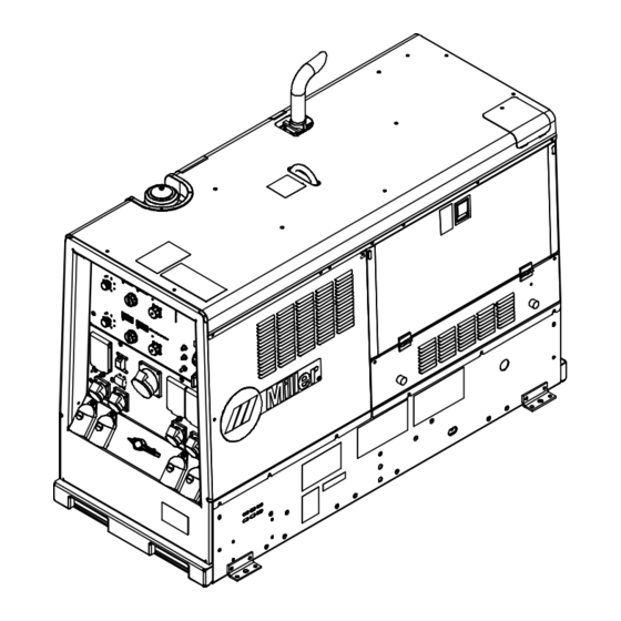
- Page 1 OM-282302J 2023-05 Processes Multiprocess Welding Description Engine Driven Welder/Generator Big Blue 700 X ® Duo Pro ® Deutz OWNER’S MANUAL For product information, Owner’s Manual translations, and more, visit www.MillerWelds.com...
- Page 2 We know you don’t have time to do it any other way. That’s why when Niels Miller first started building arc welders in 1929, he made sure his products offered long-lasting value and superior quality.
-
Page 3: Table Of Contents
TABLE OF CONTENTS SECTION 1 – SAFETY PRECAUTIONS – READ BEFORE USING..............1 Symbol Usage . - Page 4 TABLE OF CONTENTS 5-15 Making Dual Operator CC And CV Weld Connections w/ Common Work Cable ..........38 5-16 Making Single Operator CC Weld Connections .
-
Page 5: Section 1 - Safety Precautions - Read Before Using
SECTION 1 – SAFETY PRECAUTIONS – READ BEFORE USING Protect yourself and others from injury—read, follow, and save these important safety precautions and operating instructions. 1-1. Symbol Usage DANGER! – Indicates a hazardous situation which, if not avoided, will result in death or serious injury. The possible hazards are shown in the adjoining symbols or explained in the text. - Page 6 Accidental contact of electrode to metal objects can cause sparks, ex- FLYING METAL OR DIRT can injure plosion, overheating, or fire. Check and be sure the area is safe be- eyes. fore doing any welding. � Welding, chipping, wire brushing, and grinding �...
-
Page 7: Engine Hazards
� Install cylinders in an upright position by securing to a stationary � Turn face away from valve outlet when opening cylinder valve. Do support or cylinder rack to prevent falling or tipping. not stand in front of or behind the regulator when opening the valve. -
Page 8: Compressed Air Hazards
1-4. Compressed Air Hazards � Reinstall doors, panels, covers, or guards when servicing is fin- COMPRESSED AIR EQUIPMENT can ished and before starting unit. injure or kill. � If ANY air is injected into the skin or body seek medical help immediately. - Page 9 � Follow the guidelines in the Applications Manual for the Revised HIGH PRESSURE FLUIDS can injure NIOSH Lifting Equation (Publication No. 94-110) when manually or kill. lifting heavy parts or equipment. � Engine fuel system components can be under high OVERHEATING can damage motors.
-
Page 10: California Proposition 65 Warnings
� If notified by the FCC about interference, stop using the equipment � Be sure all equipment in the welding area is electromagnetically at once. compatible. � Have the installation regularly checked and maintained. � To reduce possible interference, keep weld cables as short as �... -
Page 11: Section 2 - Consignes De Sécurité - Lire Avant Utilisation
SECTION 2 – CONSIGNES DE SÉCURITÉ - LIRE AVANT UTILISATION Pour écarter les risques de blessure pour vous-même et pour autrui — lire, appliquer et ranger en lieu sûr ces consignes relatives aux précautions de sécurité et au mode opératoire. 2-1. - Page 12 � Ne pas toucher aux portes-électrodes qui sont raccordés à deux bien ventilé, et en portant un respirateur à alimentation d’air. Les machines à souder en même temps, car cela entraîne la présence revêtements et tous les métaux renfermant ces éléments peuvent d’une tension de circuit-ouvert double.
-
Page 13: Dangers Existant En Relation Avec Le Moteur
� Ne pas souder là où l’air ambiant pourrait contenir des poussières, � Les porteurs d’implants médicaux doivent consulter leur médecin gaz ou émanations inflammables (vapeur d’essence, par et le fabricant du dispositif avant de s’approcher de la zone où se exemple). -
Page 14: Dangers Liés À L'air Comprimé
� Ne pas placer l’appareil sur, au-dessus ou à proximité de surfaces � Ne pas toucher aux pièces chaudes, utiliser les outils recomman- inflammables. dés et porter des gants de soudage et des vêtements épais pour éviter les brûlures. � Tenir à distance les produits inflammables de l’échappement. LA VAPEUR ET LE LIQUIDE DE Les PIÈCES MOBILES peuvent REFROIDISSEMENT CHAUD peuvent... -
Page 15: Symboles De Dangers Supplémentaires En Relation Avec L'installation, Le Fonctionnement Et La Maintenance
L’AIR COMPRIMÉ risque de Les PIÈCES MOBILES peuvent provoquer des blessures ou même la causer des blessures. mort. � S’abstenir de toucher des parties mobiles telles � Avant d’intervenir sur le circuit d’air comprimé, que des ventilateurs, courroies et rotors. couper l’alimentation électrique, verrouiller etéti- �... - Page 16 � Utiliser uniquement des équipements adéquats pour un fonction- � Régler les commandes de charge de batterie sur la position d’arrêt nement avec une alimentation de 50/60 ou de 60 Hz. avant de brancher la batterie. Veiller à ce que les pinces de charge ne se touchent pas.
-
Page 17: Proposition Californienne 65 Avertissements
� Effectuer l’installation, l’entretien et toute intervention selon les LE SOUDAGE À L’ARC risque de manuels d’utilisateurs, les normes nationales, provinciales et de provoquer des interférences. l’industrie, ainsi que les codes municipaux. � L’énergie électromagnétique risque de provoquer LE RAYONNEMENT HAUTE des interférences pour l’équipement électronique FRÉQUENCE (H.F.) risque de sensible tel que les ordinateurs et l’équipement... - Page 18 les porteurs d’implants médicaux doivent être prises: par exemple, 5. Connecter la pince sur la pièce aussi près que possible de la des restrictions d’accès pour les passants ou une évaluation indivi- soudure. duelle des risques pour les soudeurs. Tous les soudeurs doivent ap- 6.
-
Page 19: Section 3 - Definitions
facility. Contact your local recycling office or your local distributor for further information. Safe � Complete Parts List is available at www.MillerWelds.com 1-1. Additional Safety Symbols And Definitions 1-1. Additional Safety Symbols And Definitions Do not discard product (where applicable) with general waste. 1-1. - Page 20 Cutting sparks can cause fires. Have a fire extinguisher nearby, and have a watchperson ready to use it. Do not grip material near cutting path. � Complete Parts List is available at www.MillerWelds.com Safe15 2012 Safe18 201 Do not weld on drums or any closed containers. Do not weld on drums or any closed containers.
- Page 21 device less than 60 degrees. device less than 60 degrees. Use a proper cart to move unit. Use a proper cart to move unit. Use a proper cart to move unit. � Safe44 2012 05 Complete Parts List is available at www.MillerWelds.com Safe44 2012 05 Safe44 2012 05 Keep your head out of the fumes...
-
Page 22: Miscellaneous Symbols And Definitions
Do not use ether or other starting fluids. Using starting fluids voids warranty. See engine Owner’s Manual. Do not use ether or other starting fluids. Using starting fluids voids warranty. See engine Owner’s Manual. � Complete Parts List is available at www.MillerWelds.com Safe89 20 Safe89 2017 Hot muffler, exhaust pipe, and external surfaces can burn. - Page 23 Engine Stop Welding (FCAW) Current (AC) Alternating Engine Stop Current (AC) Tungsten Inert Gas (TIG) Lift Arc Protective Earth � Tungsten Inert Complete Parts List is available at www.MillerWelds.com Run (Fast) (Ground) Gas (TIG) Lift Arc Protective Earth Run (Fast) (Ground) Engine Belt Remote...
-
Page 24: Section 4 - Specifications
Information About Default Weld Parameters And Settings NOTICE – Each welding application is unique. Although certain Miller Electric products are designed to determine and default to certain typical welding parameters and settings based upon specific and relatively limited application variables input by the end user, such default settings are for reference purposes only;... -
Page 25: Dimensions, Weights, And Operating Angles
� Complete Parts List is available at www.MillerWelds.com 4-6. Dimensions, Weights, And Operating Angles Dimensions Height 43 in. (1092 mm) (Add 7 in. for exhaust pipe) Width 28.5 in. (724 mm) (mtg. brackets turned Do not exceed tilt angles or engine could 30.75 in. -
Page 26: Volt-Ampere Curves
� Complete Parts List is available at www.MillerWelds.com 1-3. Volt-Ampere Curves 1-3. Volt-Ampere Curves 4-8. Volt-Ampere Curves 1-3. Volt-Ampere Curves A. Stick Mode A. Stick Mode The volt-ampere curves show the minimum Stick Mode and maximum voltage and amperage output A. -
Page 27: Volt-Ampere Curves For Paralleled Output
� 1-4. Volt-Ampere Curves For Paralleled Output Complete Parts List is available at www.MillerWelds.com 1-4. Volt-Ampere Curves For Paralleled Output 1-4. Volt-Ampere Curves For Paralleled Output 4-9. Volt-Ampere Curves For Paralleled Output A. Stick Mode A. Stick Mode A. Stick Mode The volt-ampere curves show the minimum Stick Mode and maximum voltage and amperage output... -
Page 28: Ac Generator Power Curves, Single Phase
A. Single Phase 4 kW � Complete Parts List is available at www.MillerWelds.com 1-5. AC Generator Power Curves, Single Phase 2 8 0 4-10. AC Generator Power Curves, Single Phase A. Single Phase 4 kW 2 6 0 The AC power curves show the generator Single Phase 4 kW power in amperes. -
Page 29: Ac Generator Power Curves, Three Phase
A. Three Phase, 240 V, 20 kW 1-6. AC Generator Power Curves, Three Phase � Complete Parts List is available at www.MillerWelds.com 4-11. AC Generator Power Curves, Three Phase A. Three Phase, 240 V, 20 kW The AC power curves show the generator Three Phase, 240 V, 20 kW power in amperes. -
Page 30: Fuel Consumption
� Complete Parts List is available at www.MillerWelds.com 4-12. Fuel Consumption The curve shows typical fuel use under weld 2.75 10.41 or power loads. 9.46 2.50 Paralleled Arc Dual Arcs 8.52 2.25 7.57 2.00 6.62 1.75 5.69 1.50 Single Arc 4.73 1.25 3.79... -
Page 31: Section 5 - Installation
� Complete Parts List is available at www.MillerWelds.com SECTION 5 – INSTALLATION 5-1. Installing Welder/Generator Movement And Airflow Clearance 18 in. 18 in. (460 mm) (460 mm) 18 in. 18 in. (460 mm) 18 in. 18 in. (460 mm) (460 mm) (460 mm) 18 in. -
Page 32: Grounding Generator To Truck Or Trailer Frame
� Complete Parts List is available at www.MillerWelds.com 5-2. Grounding Generator to Truck or Trailer Frame 1-1. Grounding Generator To Truck Or Trailer Frame GND/PE Bed liners, shipping skids, and 3 Metal Vehicle Frame Always ground generator frame to some running gear insulate the vehicle frame to prevent electric welding generator from the vehicle shock and static electricity hazards. -
Page 33: Connecting The Battery
� Complete Parts List is available at www.MillerWelds.com 5-4. Connecting The Battery 907736 / Ref. 907561 01 2-1. Connecting The Battery 1/2 in. Battery is most easily accessed through the � Never start the engine when the cables NOTICE – Lead acid batteries discharge philips head wrench crescent wrench... -
Page 34: Engine Prestart Checks
Avoid these issues by considering the following recommendations: � Weather Protection. Use a Miller Cold Weather Kit (Miller part no. 301482). Additional measures may be taken to shield the unit from the elements such as using wind barriers to reduce air flow. -
Page 35: Selecting Cable Sizes
� Complete Parts List is available at www.MillerWelds.com 5-6. Selecting Cable Sizes* NOTICE – The Total Cable Length in Weld Circuit (see table below) is the combined length of both weld cables. For example, if the power source is 100 ft (30 m) from the workpiece, the total cable length in the weld circuit is 200 ft (2 cables x 100 ft). Use the 200 ft (60 m) column to determine cable size. -
Page 36: Connecting Weld Output Cables
Complete Parts List available at www.MillerWelds.com � Complete Parts List is available at www.MillerWelds.com 5-8. Connecting Weld Output Cables Stop engine. Failure to properly connect weld cables may cause excessive heat and start a fire, or damage your machine. � Do not place anything between weld cable terminal and copper bar. -
Page 37: Making Dual Operator Cc Weld Connections W/ Separate Work Cables
� Complete Parts List is available at www.MillerWelds.com 5-10. Making Dual Operator CC Weld Connections w/ Separate Work Cables 4-1. Making Dual Operator CC Weld Connections w/ Separate Work Cables Ref. 251 340-A / Ref. 802 292-A 3/4 in. See Selecting Cable Size table for proper For Stick/TIG Direct Current Electrode Neg- Stop engine. -
Page 38: Making Dual Operator Cc Weld Connections W/ Common Work Cable
� Complete Parts List is available at www.MillerWelds.com 4-2. Making Dual Operator Mode CC Weld Connections w/ Common Work Cable 5-11. Making Dual Operator CC Weld Connections w/ Common Work Cable Ref. 251 340-A / Ref. 802 292-A 3/4 in. NOTICE –... -
Page 39: Making Dual Operator Cv Weld Connections W/ Separate Work Cables
� Complete Parts List is available at www.MillerWelds.com 5-12. Making Dual Operator CV Weld Connections w/ Separate Work Cables Ref. 251 340-A / Ref. 802 292-A 3/4 in. See Selecting Cable Size table for proper For MIG and FCAW welding Direct Current Stop engine. -
Page 40: Making Dual Operator Cv Weld Connections W/ Common Work Cable
� Complete Parts List is available at www.MillerWelds.com 5-13. Making Dual Operator CV Weld Connections w/ Common Work Cable 3/4 in. NOTICE – For common work connection, common work cable and work jumper cable Stop engine. ps head wrench crescent wrench work cable must be able to carry combined to Welder B (right) Negative (-) terminal. -
Page 41: Making Dual Operator Cc And Cv Weld Connections W/ Separate Work Cables
� Complete Parts List is available at www.MillerWelds.com 5-14. Making Dual Operator CC And CV Weld Connections w/ Separate Work Cables 4-4. Making Dual Operator CC And CV Weld Connections w/ Separate Work Cables Ref. 251 340-A / Ref. 802 292-A 3/4 in. -
Page 42: Making Dual Operator Cc And Cv Weld Connections W/ Common Work Cable
� Complete Parts List is available at www.MillerWelds.com 5-15. Making Dual Operator CC And CV Weld Connections w/ Common Work Cable Ref. 251 340-A / Ref. 802 292-A 3/4 in. NOTICE – Do not exceed machine duty Connect electrode holder cable to one Posi- Stop engine. -
Page 43: Making Single Operator Cc Weld Connections
� Complete Parts List is available at www.MillerWelds.com 5-16. Making Single Operator CC Weld Connections Ref. 251 340-A / Ref. 802 292-A 3/4 in. to Negative (-) terminals and electrode hold- Stop engine. � philips head wrench crescent wrench Direct Current Electrode Positive... -
Page 44: Section 6 - Operation
� Complete Parts List is available at www.MillerWelds.com SECTION 6 – OPERATION 6-1. Front Panel Controls (See Section 6-2) OM-282302 Page 40... -
Page 45: Description Of Front Panel Controls (See Section 6-1)
9 USB Receptacle SMAW or GTAW process, turn Adjust con- NOTICE – Diesel engines in Miller equip- trol to adjust preset amperage. With Proc- Allows software updates from a USB drive ment are meant to operate optimally at mod- ess/Contactor switch in any FCAW or (see Section 6-10). -
Page 46: Process/Contactor Switch
� Complete Parts List is available at www.MillerWelds.com 6-3. Process/Contactor Switch 1 Process/Contactor Switch Weld output terminals are energized when Process/Contactor switch is in an Electrode Hot position and the en- gine is running. Use switch to select weld process and weld output on/off control (see table below). -
Page 47: Service Menu
� Complete Parts List is available at www.MillerWelds.com 6-4. Service Menu 1 Adjust Control/Select Button Press and hold control for 5 seconds, then re- lease to access the Service Menu. Rotate the knob to scroll through the menu items. Press and release the control to access the options and information within each menu item. -
Page 48: Arc Control Settings
� Complete Parts List is available at www.MillerWelds.com 6-5. Arc Control Settings � Arc Control is not active when the Process/Contactor switch is in the following positions: Output On Remote ON/OFF: GTAW (Remote TIG) Complete Parts List is available at w Process/Contactor Switch Arc Control Complete Parts List is available at w... -
Page 49: Dynamic Dig Settings
Drag electrode across workpiece like striking a match; lift electrode slightly after touching work. If arc goes out electrode was lifted too high. If electrode sticks to workpiece, use a quick twist to free it. � Miller recommends Hobart filler metals. OM-282302 Page 45... -
Page 50: Lift-Arc™ Tig With Auto-Stop™ And Auto-Crater
Remote control is not needed when us- ing Auto-Crater. 1. While welding. 2. Lift torch slightly to start Auto-Crater end (current is reduced). 3. Lower torch. Weld current ramps down. 4. Shielding gas continues until shut off. � Miller recommends Hobart filler metals. OM-282302 Page 46... -
Page 51: Remote Voltage/Amperage Control
� Complete Parts List is available at www.MillerWelds.com 6-9. Remote Voltage/Amperage Control Complete Parts List available at www.MillerWelds.com 1-1. Voltage/Amperage Control With 14-Pin Remote Accessory Remote Receptacle 277074-C Connect optional remote control to receptacle. 1 Remote Receptacle When a remote control is con- Big Blue 800 Duo Air Pak shown. -
Page 52: Updating Software
� Complete Parts List is available at www.MillerWelds.com 6-10. Updating Software Preparing For Software Update Step 1. Verify the current software version installed. Press and hold the Adjust Control/Select button for 5 seconds, then release to access the Service Menu. Step 2. -
Page 53: Summary File
� Complete Parts List is available at www.MillerWelds.com 6-11. Summary File 1 Summary File Each time a USB stick is inserted in the USB receptacle, a summary file is saved to the USB stick as SummaryFile.txt. "USB ACC" will display as the file is written. File is complete when display no longer shows "USB ACC."... -
Page 54: Fuel/Hour Gauge Descriptions
� Complete Parts List is available at www.MillerWelds.com 11-25. Fuel/Hour Gauge Descriptions 6-12. Fuel/Hour Gauge Descriptions OM-282302 Page 50... -
Page 55: Associating Arcreach
� Complete Parts List is available at www.MillerWelds.com 6-13. Associating ArcReach Devices (ArcReach Models Only) ® Stop engine. NOTICE – Do not exceed machine duty cycle. Associating ArcReach Device To Engine Driven Welder/Generator Make connections between welder/generator and ArcReach device. See Owner’s Manual for ArcReach device for typical connection diagrams. -
Page 56: Section 7 - Operating Auxiliary Equipment
� Complete Parts List is available at www.MillerWelds.com SECTION 7 – OPERATING AUXILIARY EQUIPMENT 7-1. Export Auxiliary Power Receptacles Ref. 264 998 CB1 protects RC5 from overload. If supple- CB8 protects GFCI2 and RC2 from over- 1 110 V 16 A AC Receptacle RC1 mentary protector opens, the receptacle load. -
Page 57: Gfci Receptacle Information, Resetting, And Testing
� Complete Parts List is available at www.MillerWelds.com 7-2. GFCI Receptacle Information, Resetting, And Testing Use GFCI protection when operating If a ground fault is detected, the GFCI Reset Resetting GFCI Receptacles auxiliary equipment. If unit does not button pops out, and the circuit opens to dis- If a GFCI fault occurs, stop engine and dis- have GFCI receptacles, use GFCI- connect power to the faulty equipment. -
Page 58: Section 8 - Maintenance And Troubleshooting
SECTION 8 – MAINTENANCE AND TROUBLESHOOTING SECTION 3 MAINTENANCE & TROUBLESHOOTING 8-1. Maintenance Label OM-282302 Page 54 OM-282302 Page 26... -
Page 59: Routine Maintenance
Technical Manual. � = Check ◇ = Change � = Clean � = Replace Reference When servicing a Miller gasoline-powered welder/generator, always perform the following basic el, see Section __. engine checks before contacting the engine manufacturer. Every Engine FUEL Manual, el is too low. -
Page 60: Checking Generator Brushes
8-3. Checking Generator Brushes Stop engine and let cool. 1 Generator Brush 2 Minimum Length: 5/8 in. (16 mm) 3 New Length: 1–1/4 in. (32 mm) 4 Damaged Brush Mark and disconnect leads at brushholder cap. Remove brushes. Replace brushes if damaged or if brush ma- terial is at or near minimum length. -
Page 61: Servicing Air Cleaner
NOTE: This standard is now used for IED/PED models with plastic air cleaner housing. 8-5. Servicing Air Cleaner Stop engine. NOTICE – Do not run engine without air cleaner or with dirty element. Engine dam- age caused by using a damaged element is not covered by the warranty. -
Page 62: Adjusting Engine Speed
8-6. Adjusting Engine Speed Stop engine and let cool. � For operation at high altitude, engine may require adjustment. If adjustment is necessary, contact engine manufac- turer’s Factory Authorized Service Agent. Engine speed is factory set and should not require adjustment. After tuning engine, check engine no load speed with a tachome- ter or frequency meter (see table for no load speeds). -
Page 63: Servicing Fuel And Lubrication Systems
8-7. Servicing Fuel And Lubrication Systems tools/ maintenance label for oil/filter change See engine manual. Stop engine and let cool. flathead philips head wrench crescent wrench information. After servicing, start engine and Close doors. check for fuel leaks. Stop engine, To drain water from fuel system: To drain sludge from fuel tank: tighten connections as necessary,... -
Page 64: Overload Protection
8-8. Overload Protection 3-1. Overload Protection Stop engine. � When a supplementary protector, cir- cuit breaker or fuse opens, it usually in- dicates a more serious problem exists. Contact Factory Authorized Service Agent. 1 Fuse F1 2 Fuse F2 F1 and F2 protect the stator exciter winding from overload. -
Page 65: Voltmeter/Ammeter Error Displays
8-9. Voltmeter/Ammeter Error Displays Display Example Use the Voltmeter/Ammeter error displays to diagnose and correct fault conditions. � When an error is displayed, normally weld output has stopped but generator power output may be okay. � To reset error displays, stop unit and then restart. See below to reset CHEK REMT display. Error Display Description CHEK REMT... - Page 66 Trouble Remedy Check engine speed, and adjust if necessary. Check fuses F1 and F2, and replace if open (see Section 8-8). Have Factory Authorized Service Agent check integrated rectifier SR2, capacitor C6, and the rotor. Low open-circuit voltage. Check engine speed, and adjust if necessary. Check position of Process/Contactor switch.
- Page 67 Trouble Remedy Check battery and replace if necessary. Check engine charging system according to engine manual. Have Factory Authorized Service Agent check control relay CR5, fuel pump, and fuel solenoid FS1. Air in fuel system. See engine manual. Engine starts, but stops when Engine Check oil level.
-
Page 68: Section 9 - Parts List
� Complete Parts List is available at www.MillerWelds.com SECTION 9 – PARTS LIST 9-1. Recommended Spare Parts Item No. Dia. Mkgs. Part No. Description Quantity 284184 USB Flash Drive F1, F2 085874 Fuse, Mintr Cer Slo-blo 10 Amp 250 Volt 190823 Brush, Contact Elect .250 X.500 X 1.250 Grd Ay ♦192939... - Page 69 OM-282302 Page 65...
-
Page 70: Section 10 - Electrical Diagrams
SECTION 10 – ELECTRICAL DIAGRAMS Figure 10-1. Circuit Diagram For Big Blue 700 X Duo Pro OM-282302 Page 66... - Page 71 OM-282302 Page 67...
-
Page 72: Section 11 - Run-In Procedure
SECTION 11 – RUN-IN PROCEDURE NOTICE – Diesel engines in Miller equipment are meant to operate optimally at moderate to rated load. Using light or no load for extended peri- ods of time may cause wetstacking or other engine damage. Do not idle engine longer than necessary. -
Page 73: Run-In Procedure Using Load Bank Or Resistance Grid
11-2. Run-In Procedure Using Load Bank Or Resistance Grid Stop engine. Connect load bank or resistor grid to gener- For Resistance Grid ator Side A weld output terminals using Do not touch hot exhaust pipe, en- Set grid switches and then adjust gener- proper size weld cables with correct connec- gine parts, or load bank/grid. -
Page 74: Section 12 - Generator Power Guidelines
SECTION 12 – GENERATOR POWER GUIDELINES � The views in this section are intended to be representative of all engine-driven welder/generators. Your unit may differ from those shown. 12-1. Selecting Equipment 1 Generator Power Receptacles – Neutral Bonded To Frame 2 3-Prong Plug From Case Grounded Equipment 3 2-Prong Plug From Double Insulated... - Page 75 12-3. Grounding When Supplying Building Systems 1 Equipment Grounding Terminal 2 Grounding Cable GND/PE Use #8 AWG or larger insulated copper wire. 3 Ground Device � Use ground device as stated in electri- cal codes. Ground generator to system earth ground if supplying power to a premises (shop,...
- Page 76 12-5. Approximate Power Requirements For Industrial Motors Industrial Motors Rating Starting Watts Running Watts Split Phase 1/8 HP 1/6 HP 1225 1/4 HP 1600 1/3 HP 2100 1/2 HP 3175 Capacitor Start-Induction Run 1/3 HP 2020 1/2 HP 3075 3/4 HP 4500 1400 1 HP...
- Page 77 12-7. Approximate Power Requirements For Contractor Equipment Contractor Equipment Rating Starting Watts Running Watts Hand Drill 1/4 in. 3/8 in. 1/2 in. Circular Saw 6-1/2 in. 7-1/4 in. 8-1/4 in. 1400 1400 Table Saw 9 in. 4500 1500 10 in. 6300 1800 Band Saw...
- Page 78 12-8. Power Required To Start Motor 1 Motor Start Code 2 Running Amperage 3 Motor HP 4 Motor Voltage AC MOTOR VOLTS AMPS Step 1: Find code and use table to find kVA/ CODE HP. If code is not listed, multiply running am- PHASE perage by six to find starting amperage.
- Page 79 12-10. Typical Connections To Standby Power 1. Utility Electrical 2. Transfer Switch 3. Fused Disconnect 4. Welder/Generator Service Switch (If Required) Output 5. Essential Loads Have only qualified persons perform 1 Utility Electrical Service 4 Welder/Generator Output these connections according to all 2 Transfer Switch (Double-Throw) Generator output voltage and wiring must applicable...
- Page 80 12-11. Selecting Extension Cord (Use Shortest Cord Possible) A. Cord Lengths For 120 Volt Loads Use GFCI protection when operating auxiliary equipment. If unit does not have GFCI receptacles, use GFCI-protected extension cord. Do not use GFCI receptacles to power life support equipment. Maximum Allowable Cord Length In ft (m) for Conductor Size In AWG (mm Current (Amperes)
- Page 81 Notes...
- Page 82 Notes...
- Page 83 Effective January 1, 2023 (Equipment with a serial number preface of ND or newer) This limited warranty supersedes all previous Miller warranties and is exclusive with no other guarantees or war- ranties expressed or implied. � CoolBelt, PAPR Blower, and PAPR Face...
- Page 84 Appleton, WI 54914 USA tact your distributor and/or equipment manu- facturer’s Transportation Department. International Headquarters–USA USA Phone: 920-735-4505 USA & Canada FAX: 920-735-4134 International FAX: 920-735-4125 For International Locations Visit www.MillerWelds.com ORIGINAL INSTRUCTIONS – PRINTED IN USA © Miller Electric Mfg. LLC 2023-05...
Need help?
Do you have a question about the Big Blue Duo Pro 700 X and is the answer not in the manual?
Questions and answers