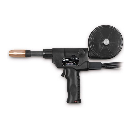
Miller Spoolmatic - Pro 30A Owner's Manual
Welding guns
Hide thumbs
Also See for Spoolmatic - Pro 30A:
- Owner's manual (53 pages) ,
- Technical manual (76 pages) ,
- Owner's manual (32 pages)

Related Manuals for Miller Spoolmatic - Pro 30A


Summary of Contents for Miller Spoolmatic - Pro 30A
- Page 1 OM-264 713B 2014−08 Processes MIG (GMAW) Welding Description Semi-Automatic, Air-Cooled, MIG (GMAW) Welding Gun Spoolmatic - Pro 15A And 30A File: MIG (GMAW) Visit our website at www.MillerWelds.com...
- Page 2 We know you don’t have time to do it any other way. That’s why when Niels Miller first started building arc welders in 1929, he made sure his products offered long-lasting value and superior quality.
-
Page 3: Table Of Contents
TABLE OF CONTENTS SECTION 1 −SAFETY PRECAUTIONS FOR GMAW WELDING GUNS − READ BEFORE USING ..1-1. Symbol Usage ............... . 1-2. -
Page 5: Section 1 −Safety Precautions For Gmaw Welding Guns − Read Before Using
SECTION 1 −SAFETY PRECAUTIONS FOR GMAW WELDING GUNS − READ BEFORE USING SR7 (MIG) 2013-09 Protect yourself and others from injury — read, follow, and save these important safety precautions and operating instructions. 1-1. Symbol Usage DANGER! − Indicates a hazardous situation which, if Indicates special instructions. -
Page 6: Proposition 65 Warnings
NOISE can damage hearing. READ INSTRUCTIONS. D Read and follow all labels and the Owner’s Noise from some processes or equipment can damage hearing. Manual carefully before installing, operating, or servicing unit. Read the safety information at D Check for noise level limits exceeding those the beginning of the manual and in each specified by OSHA. -
Page 7: Utilisation
SECTION 2 − MESURES DE SÉCURITÉ VISANT LES PISTOLETS DE SOUDAGE GMAW − À LIRE AVANT UTILISATION SR7(MIG)_2013−09 fre Pour écarter les risques de blessure pour vous−même et pour autrui — lire, appliquer et ranger en lieu sûr ces consignes relatives aux précautions de sécurité... -
Page 8: Proposition Californienne 65 Avertissements
D Avoir recours à des écrans protecteurs ou à des rideaux pour D Utiliser des bouche-oreilles ou des serre-tête antibruit approuvés si protéger les autres contre les rayonnements les éblouissements le niveau de bruit est élevé. et les étincelles ; prévenir toute personne sur les lieux de ne pas D Avertir les personnes à... - Page 9 Maintenir la tête et le torse aussi loin que possible du matériel du Ne pas souder tout en portant la source de soudage ou le dévidoir. circuit de soudage. En ce qui concerne les implants médicaux : Connecter la pince sur la pièce aussi près que possible de la Les porteurs d’implants doivent d’abord consulter leur médecin avant soudure.
- Page 10 OM-264 713 Page 6...
-
Page 11: Section 3 − Definitions
SECTION 3 − DEFINITIONS 3-1. Additional Safety Symbols And Definitions Some symbols are found only on CE products. Warning! Watch Out! There are possible hazards as shown by the symbols. Safe1 2012−05 3-2. Miscellaneous Symbols And Definitions Primary Voltage Volts Primary Current Amperes Degree Of... -
Page 12: Section 4 − Specifications
SECTION 4 − SPECIFICATIONS 4-1. Gun Specifications Approximate Wire Diameter Cooling Maximum Overall Wire Feed Weld Circuit Rating Weight Range Method Spool Size Dimensions Range 2.9 lb (1.3 kg) Length: 15-3/8 in. Gun Only (390 mm) .030 Thru 1/16 in. 70 To 900 ipm 100 Volts, 200 Amperes, 4 in. -
Page 13: Connecting To 115 Volt Weld Control
5-2. Connecting To 115 Volt Weld Control 115 Volt Weld Control Gas Hose Connect to regulator/flowmeter. Trigger Control Cord Insert plug into receptacle, and tighten threaded collar. Weld Cable Positive (+) Weld Output Terminal In Control Connect weld cable to positive (+) weld output terminal in weld control. -
Page 14: Installing Wire Spool And Threading Welding Wire
5-4. Installing Wire Spool And Threading Welding Wire Pressure Arm Lever To release drive roll pressure, pull back on pressure arm lever. While pulled back, shift to left onto shoulder to lock into place. Canister Inlet Guide Drive Roll Grove Top Cover Thumbscrew (Canister Rotation) -
Page 15: Adjusting Drive Roll And Spool Brake Pressure
5-5. Adjusting Drive Roll And Spool Brake Pressure Top Cover Canister Cover Thumbscrew Loosen thumbscrew and remove cover. Spool Cut welding wire off at contact tip. Retract wire onto spool and secure. Spool Brake Thumbnut Grasp spool in one hand and turn while adjusting spool brake thumb- nut. -
Page 16: Installing Gas Supply
5-7. Installing Gas Supply Obtain gas cylinder and chain to running gear, wall, or other station- ary support so cylinder cannot fall and break off valve. Cylinder Valve Remove cap, stand to side of valve, and open valve slightly. Gas flow blows dust and dirt from valve. -
Page 17: Section 6 − Operation
SECTION 6 − OPERATION 6-1. Gun Controls Trigger Press trigger to energize welding power source contactor (if applicable), start shielding gas flow, and begin wire feed. Wire Speed Control Use control to fine adjust wire feed speed set on wire feeder Weld Speed control. -
Page 18: Shielding Gas
6-3. Shielding Gas Shielding Gas Cylinder Valve Gun Trigger Open valve on cylinder just before welding. Gun trigger turns weld output and gas flow on and off (see Section 6-1). Close valve on cylinder when finished welding. sb5.1 6/92 − S-0621-C / Ref. T0050 SECTION 7 −... -
Page 19: Replacing Canister Inlet Guide
7-1. Replacing Canister Inlet Guide Top Cover Pressure Arm Lever Cut off welding wire where it enters pressure roll assembly area. Nozzle Pull wire out nozzle. Thumbscrew Canister Cover Loosen thumbscrew and remove cover. Wire Spool Spool Brake Thumbnut Loosen thumbnut, retract wire onto spool, secure, and remove spool. -
Page 20: Replacing Head Tube Liner
7-3. Replacing Head Tube Liner Turn Off coolant supply before removing head tube water-cooled gun. The standard head tube liner (yellow) will accommodate wire diameters from 3/64 in. - 1/16 in. wire size. When changing wire size, change gun drive roll. Cover Head Tube Remove head tube from gun. -
Page 21: Changing Gun Contact Tip
7-5. Changing Gun Contact Tip Remove nozzle Nozzle FasTip Unscrew FasTip. Install new FasTip. Ref. 150 437-A 7-6. Gun Drive Assembly Maintenance Lever Arm Remove pressure on wire by pulling lever arm forward. Pull to left to lock into place. Retract wire onto spool. -
Page 22: Troubleshooting
7-7. Troubleshooting Disconnect power before troubleshooting. Trouble Remedy No weld output; gun/feeder does not Secure weld control plug in 115 volts AC receptacle (see weld control Owner’s Manual). work. Place Power switch on welding power source in the On position (see welding power source Owner’s Manual). - Page 23 Notes OM-264 713 Page 19...
-
Page 24: Section 8 − Electrical Diagrams
SECTION 8 − ELECTRICAL DIAGRAMS Ref. M1499 Figure 8-1. Circuit Diagram For Spoolmatic Pro Gun Notes OM-264 713 Page 20... - Page 25 Notes OM-264 713 Page 21...
-
Page 26: Section 9 − Parts List
SECTION 9 − PARTS LIST Hardware is common and not available unless listed. Figure 9-1. Exploded View Of Spoolmatic Pro Gun OM-264 713 Page 22... - Page 27 Item Part Description Quantity Figure 9-1. Exploded View Of Spoolmatic Pro Gun ... . . 257 353 Kit, Handle XR Pistol Pro/Plus ........
- Page 28 Item Diagram Part Description marking Quantity Figure 9-1. Exploded View Of Spoolmatic Pro Gun (Continued) ... . 148 489 Washer, Anti−turn .380 Id ......... . .
- Page 29 Notes OM-264 713 Page 25...
-
Page 30: Section 10 − Parts List Including Consumables
SECTION 10 − PARTS LIST INCLUDING CONSUMABLES Item Number A/C OUTER 1805 (M1366) (230 679) .030−1/16” WIRE COLLARED 4.0” STRAIGHT A/C (255 716) INSULATOR (229 670) (232 284) (230 678) Ref. T0031 Figure 10-1. Consumables Flowchart Item Part Description Quantity Consumables Flowchart Table 10-1. - Page 31 Item Part Description Quantity Consumables Flowchart (Continued) Table 10-2. Heavy Duty FasTipt Contact Tips* ... 206 185 .030 in. (0.8 mm) ........... .
- Page 32 Notes...
- Page 33 Notes...
- Page 34 Notes...
- Page 35 Effective January 1, 2014 (Equipment with a serial number preface of ME or newer) This limited warranty supersedes all previous Miller warranties and is exclusive with no other guarantees or warranties expressed or implied. Warranty Questions? LIMITED WARRANTY − Subject to the terms and conditions below, 6 Months —...
- Page 36 Contact the Delivering Carrier to: File a claim for loss or damage during shipment. For assistance in filing or settling claims, contact your distributor and/or equipment manufacturer’s Transportation Department. ORIGINAL INSTRUCTIONS − PRINTED IN USA 2014 Miller Electric Mfg. Co. 2014−01...
Need help?
Do you have a question about the Spoolmatic - Pro 30A and is the answer not in the manual?
Questions and answers