Table of Contents
Advertisement
Quick Links
Visit our website at
www.MillerWelds.com
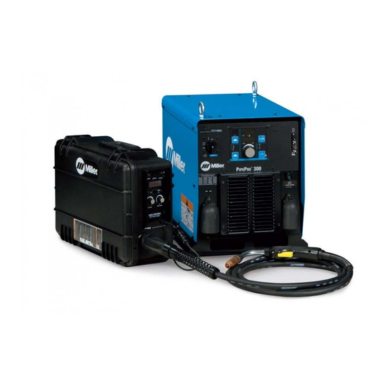
PipePro 300
OM-246 466B
Processes
Stick (SMAW) Welding
MIG (GMAW) Welding
RMD (Modified Short Circuit)
Pulsed MIG (GMAW-P)
Flux Cored (FCAW) Welding
TIG (GTAW) Welding
Multiprocess Welding
Description
Arc Welding Power Source
R
File: Pipe Welding Products
2010−07
Advertisement
Table of Contents

Subscribe to Our Youtube Channel
Related Manuals for Miller PipePro 300


Summary of Contents for Miller PipePro 300
- Page 1 2010−07 Processes Stick (SMAW) Welding MIG (GMAW) Welding RMD (Modified Short Circuit) Pulsed MIG (GMAW-P) Flux Cored (FCAW) Welding TIG (GTAW) Welding Multiprocess Welding Description Arc Welding Power Source PipePro 300 File: Pipe Welding Products Visit our website at www.MillerWelds.com...
- Page 2 We know you don’t have time to do it any other way. That’s why when Niels Miller first started building arc welders in 1929, he made sure his products offered long-lasting value and superior quality.
-
Page 3: Table Of Contents
............4-14. Welding Stainless Steel With And Without Backing Gas Using PipePro 300 . - Page 4 TABLE OF CONTENTS SECTION 5 − MAINTENANCE ..............5-1.
-
Page 5: Section 1 − Safety Precautions - Read Before Using
SECTION 1 − SAFETY PRECAUTIONS - READ BEFORE USING som _2010−03 Protect yourself and others from injury — read and follow these precautions. 1-1. Symbol Usage DANGER! − Indicates a hazardous situation which, if Indicates special instructions. not avoided, will result in death or serious injury. The possible hazards are shown in the adjoining symbols or explained in the text. - Page 6 D Keep your head out of the fumes. Do not breathe the fumes. D Wear oil-free protective garments such as leather gloves, heavy shirt, cuffless trousers, high shoes, and a cap. D If inside, ventilate the area and/or use local forced ventilation at the arc to remove welding fumes and gases.
-
Page 7: Additional Symbols For Installation, Operation, And Maintenance
1-3. Additional Symbols For Installation, Operation, And Maintenance FIRE OR EXPLOSION hazard. MOVING PARTS can injure. D Do not install or place unit on, over, or near D Keep away from moving parts such as fans. combustible surfaces. D Keep all doors, panels, covers, and guards D Do not install unit near flammables. -
Page 8: California Proposition 65 Warnings
1-4. California Proposition 65 Warnings For Gasoline Engines: Welding or cutting equipment produces fumes or gases which contain chemicals known to the State of California to Engine exhaust contains chemicals known to the State of cause birth defects and, in some cases, cancer. (California California to cause cancer, birth defects, or other reproduc- Health &... -
Page 9: Section 2 − Consignes De Sécurité − Lire Avant Utilisation
SECTION 2 − CONSIGNES DE SÉCURITÉ − LIRE AVANT UTILISATION fre_som_2010−03 Se protéger et protéger les autres contre le risque de blessure — lire et respecter ces consignes. 2-1. Symboles utilisés DANGER! − Indique une situation dangereuse qui si on Indique des instructions spécifiques. - Page 10 Il reste une TENSION DC NON NÉGLIGEABLE dans LE SOUDAGE peut provoquer un les sources de soudage onduleur UNE FOIS incendie ou une explosion. l’alimentation coupée. Le soudage effectué sur des conteneurs fermés tels D Arrêter les convertisseurs, débrancher le courant électrique et que des réservoirs, tambours ou des conduites peut décharger les condensateurs d’alimentation selon les instructions provoquer leur éclatement.
-
Page 11: Dangers Supplémentaires En Relation Avec L'installation, Le Fonctionnement Et La Maintenance
ACCUMULATIONS LES BOUTEILLES peuvent exploser risquent de provoquer des blessures si elles sont endommagées. ou même la mort. Des bouteilles de gaz protecteur contiennent du gaz sous haute pression. Si une bouteille est endom- D Fermer l’alimentation du gaz protecteur en cas magée, elle peut exploser. -
Page 12: Proposition Californienne 65 Avertissements
Les PIÈCES MOBILES peuvent RAYONNEMENT HAUTE causer des blessures. FRÉQUENCE (H.F.) risque provoquer des interférences. D Ne pas s’approcher des organes mobiles. D Ne pas s’approcher des points de coincement D Le rayonnement haute fréquence (H.F.) peut tels que des rouleaux de commande. provoquer des interférences avec les équi- pements de radio−navigation et de com- munication, les services de sécurité... -
Page 13: Principales Normes De Sécurité
2-5. Principales normes de sécurité Safety in Welding, Cutting, and Allied Processes, ANSI Standard Z49.1, 25 West 43rd Street, New York, NY 10036 (téléphone : 212-642-4900, de Global Engineering Documents (téléphone : 1-877-413-5184, site site Internet : www.ansi.org). Internet : www.global.ihs.com). Standard for Fire Prevention During Welding, Cutting, and Other Hot Safe Practices for the Preparation of Containers and Piping for Welding Work, NFPA Standard 51B, de National Fire Protection Association,... - Page 14 OM-246 466 Page 10...
-
Page 15: Section 3 − Installation
SECTION 3 − INSTALLATION Appearance of actual unit may vary from unit shown in manual. 3-1. Specifications Amperes Input At Rated Load Output 60 Hz, Amper- Three-Phase Rated Open Input age/Volt- Input Input Welding Circuit Power Output Voltage 208 V 230 V 380 V 400V... -
Page 16: Duty Cycle And Overheating
3-3. Duty Cycle And Overheating Duty Cycle is percentage of 10 minutes that unit can weld at rated load without overheating. If unit overheats, thermostat(s) opens, output stops, and cooling fan runs. Wait fifteen minutes for unit to cool. Reduce amperage or duty cycle before welding. -
Page 17: Serial Number And Rating Label Location
3-4. Serial Number And Rating Label Location The serial number and rating information for this product is located on the back. Use rating label to determine input power requirements and/or rated output. For future reference, write serial number in space provided on back cover of this manual. 3-5. -
Page 18: Proper Ring Terminal Connection To Volt Sense Lead
3-6. Proper Ring Terminal Connection To Volt Sense Lead Front View 2 in. 1/4 in. 3/8 in. 1 in. 59 ft Tools Needed: 208 810 If volt sense lead is cut or broken at end Jacket Cut off shield at end of jacket. with ring terminal, be sure that new ring ter- Inner Core minal is connected as shown. -
Page 19: Connecting To Weld Terminals
3-8. Connecting To Weld Terminals If using an electrode negative (straight polarity) process, the volt sense lead must be connected to the work. Do not place anything between weld cable terminal and copper bar. Tools Needed: 3/4 in. (19 mm) Correct Installation Incorrect Installation 243 893-A / 803 778-A... -
Page 20: Selecting Weld Cable Sizes
**Weld cable size (AWG) is based on either a 4 volts or less drop or a current density of at least 300 circular mils per ampere. ( ) = mm for metric use ***For distances longer than those shown in this guide, call a factory applications rep. at 920-735-4505 (Miller) or 1-800-332-3281 (Hobart) Ref. S-0007-G 2009−08 OM-246 466 Page 16... -
Page 21: Arranging Welding Cables To Reduce Welding Circuit Inductance (Suitcase Feeder)
3-10. Arranging Welding Cables To Reduce Welding Circuit Inductance (Suitcase Feeder) Welding Power Source Electrode Cable Extension Cable (Optional) Work Cable Volt Sense Lead Wire Feeder Workpiece The method used to arrange cables has significant affect welding properties. As an example, RMD welding process can produce high welding circuit inductance depending on cable length and arrangement. -
Page 22: Voltage Sensing Lead And Work Cable Connections For Multiple Welding Arcs (Suitcase Feeder)
3-11. Voltage Sensing Lead And Work Cable Connections For Multiple Welding Arcs (Suitcase Feeder) A. Bad Setup 243 906-A Welding Power Source Workpiece across the workpiece will not be measured correctly for the voltage feedback signal. Electrode Cable This arrangement is a bad setup due to Voltage feedback to the welding power Extension Cable (Optional) sensing leads being directly in the current... - Page 23 B. Ideal Setup 243 908-A Welding Power Source Wire Feeder the welding power sources. The most accurate voltage sensing may not be Electrode Cable Workpiece achieved due to voltage drops in the Extension Cable (Optional) workpiece. This require Work Cable This arrangement is a better setup for compensation in the welding parameters.
-
Page 24: Rear Panel Receptacles And Supplementary Protectors
3-12. Rear Panel Receptacles And Supplementary Protectors 115 V 10 A AC Receptacle RC2 Receptacle supplies single-phase power. Maximum output from RC2 is limited by supplementary protector CB1 to 10 amps. Supplementary Protector CB1 Supplementary Protector CB2 CB1 protects 115 volt receptacle RC2 from overload. -
Page 25: Peripheral Receptacle Functions
3-13. Peripheral Receptacle Functions Function Socket Socket Information Not used. Not used. Circuit common. Not used. Contact closure to F indicates coolant flow switch is closed and recirculating coolant system is Coolant Flow operational. Switch Input Signal Circuit common. Not used. Not used. -
Page 26: Motor Control Receptacle Functions
3-14. Motor Control Receptacle Functions Socket Socket Information Not used. +40 volts dc. Not used. +40 volts dc return. Not used. Not used. Electrode sense. Not used. Not used. Not used. Ref. 803 675-A 3-15. Remote 14 Receptacle Information Socket Socket Information +40 volts dc with respect to socket G. -
Page 27: Electrical Service Guide
3-16. Electrical Service Guide Failure to follow these fuse and circuit breaker recommendations could create an electric shock or fire hazard. These recommendations are for a dedicated branch circuit that applies to the rated output and duty cycle of the welding power source. INCORRECT INPUT POWER can damage this welding power source. -
Page 28: Connecting Input Power
3-17. Connecting Input Power = GND/PE Earth Ground WARNING ELECTRIC SHOCK can kill; SIGNIFICANT DC VOLTAGE exists after removal of input power. S Always wait 5 minutes after power Is turned off before working on unit. S Check input capacitor voltage, and be sure it is near 0 before touching any parts. -
Page 29: Section 4 − Operation
SECTION 4 − OPERATION 4-1. Operational Terms The following is a list of terms and their definitions as they apply to this interface unit: General Terms: Adjust Control knob used to change or set parameters and functions. Amps Indicates average amperage while welding and 3 seconds hold value at end of weld. Arc Adjust Term used to represent arc length adjustments in RMD-Pro programs. -
Page 30: Front Panel Controls (See Section 4-3)
4-2. Front Panel Controls (See Section 4-3) When an LED is lit, it means the related function is active. 200 410 Program Display Press and hold button to see program name. Gas Type LED Custom programs are named using optional Displays the number of the active program. -
Page 31: Front Panel Controls - Continued (See Section 4-2)
4-3. Front Panel Controls - Continued (See Section 4-2) Arc Control LED to show weld amperage or wire feed speed in 14 Volts And Arc Adjust LEDs lower display (the applicable LED under the The lit LED indicates whether voltage or arc The LED lights to indicate the Arc Control lower display lights to indicate which is length is being displayed. -
Page 32: Typical Connection Diagram For Mig (Gmaw) Equipment Using A Suitcase Feeder
4-4. Typical Connection Diagram For MIG (GMAW) Equipment Using A Suitcase Feeder Welding Power Source Attach volt sense lead to work clamp and attach work clamp as close to arc as possible. Negative Volt Sense Cable Connect plug on end of volt sense cable to volt sense receptacle on front of welding power source. -
Page 33: Pipepro 300 Set Up For Mig (Gmaw) Equipment
4-5. PipePro 300 Set Up For MIG (GMAW) Equipment See Table 4-1 for selection choices. Turn welding power source Power switch on (approximately 30 seconds for complete operation). Push Program button. Use the Adjust knob to choose a desired program number from the 1 through 8 selection. -
Page 34: Typical Connection Diagram For Tig (Gtaw) Equipment
4-6. Typical Connection Diagram For TIG (GTAW) Equipment Welding Power Source Interconnect Cable Connect 14-pin socket into remote foot control cable or optional extension cable. Connect 72-pin connector to I/O receptacle RC72 on rear of power source. Connect 10-pin connector into receptacle RC8 on rear of power source. -
Page 35: Pipepro 300 Set Up For Lift Tig (Gtaw) Equipment
Lift TIG cannot have the Volt Sense lead connected to the PipePro 300 when connected for Electrode Negative (straight polarity). Push Setup button again. The display will read PROG LOAD and welding power source is now ready for the welding operation. -
Page 36: Typical Connection Diagram For Stick (Smaw) Equipment
4-8. Typical Connection Diagram For Stick (SMAW) Equipment Welding Power Source Interconnect Cable Connect 14-pin socket into remote foot control cable or optional extension cable. Connect 72-pin connector to I/O receptacle RC72 on rear of power source. Connect 10-pin connector into receptacle RC8 on rear of power source. -
Page 37: Pipepro 300 Set Up For Stick (Smaw) Equipment
If Remote control is selected, connect a remote device using a remote cable adapter (300 248) to connect to an Interconnect Cable and then connect this cable to the PipePro 300. The remote device and the welding power source are now in a master/slave control configuration. The Adjust knob on the welding power source is used to control the maximum amperage that can be set by the remote device. -
Page 38: Isolating Two Processes Using Polarity Reversing/Isolation Control (042 871) Without Hf Unit
4-10. Isolating Two Processes Using Polarity Reversing/Isolation Control (042 871) Without HF Unit Electrode 1 Electrode 2 A Terminal B Terminal C Terminal WIRE FEEDER DRIVE MOTOR POLARITY REVERSING SWITCH #1 E #2 FROM WORK POWER SOURCE E #1 Tools Needed: 13/16 in. -
Page 39: Isolating Three Processes Using Polarity Reversing/Isolation Control (042 871) Without Hf Unit
4-11. Isolating Three Processes Using Polarity Reversing/Isolation Control (042 871) Without HF Unit Electrode 1 Electrode 2 A Terminal Bus Bar B Terminal C Terminal POLARITY REVERSING SWITCH #2 E #2 JUMPER A TO B POLARITY REVERSING SWITCH #1 E #2 STICK FROM E #1... - Page 40 85% Argon, 15% CO 0.045 85% Argon, 15% CO Pulse Inconel INCO 0.045 75% Argon, 25% Helium HE25 *PipePro 300 does not require a gas mixture selection for this process. See wire manufacturer for recommended gas mixture. OM-246 466 Page 36...
- Page 41 Ctrl Remt 300248 required) *PipePro 300 does not require a gas mixture selection for this process. See wire manufacturer for recommended gas mixture. **Wire diameter for self-shielded flux cored wire must not exceed 0.062 in. (1.6 mm). OM-246 466 Page 37...
-
Page 42: Front Panel Switches
4-12. Front Panel Switches Ref. 803 246-B Power Switch Contactor LED WAIT Contactor LED illuminates when weld output is Turns unit On or Off. PLS WAIT is an abbreviation for ”network energized. updating” and means the internal control PDA Port network is powering up. -
Page 43: Basic Parameters For Pipepro 300
4-13. Basic Parameters For PipePro 300 Steel Wire Size Wire Feed Speed Arc Adjust/Trim Arc Control Shielding Gas Process in (mm) IPM (mpm) .035 (0.9) 100-300 w/200 Nominal 47-53 w/50 Nominal 90/10 (2.5-7.7 w/5.1 Nominal) .035 (0.9) 100-300 w/200 Nominal... - Page 44 Steel Wire Size Wire Feed Speed Arc Adjust/Trim Arc Control Shielding Gas Process in (mm) IPM (mpm) .035 (0.9) 120-300 w/200 Nominal 52-57 w/54 Nominal 90/10 (3.0-7.6 w/5.1 Nominal) .035 (0.9) 120-300 w/200 Nominal 52-57 w/54 Nominal 30-35 85/15 (3.0-7.6 w/5.1 Nominal) .040 (1.0) 120-250 w/175 Nominal 52-56 w/54 Nominal...
- Page 45 Stainless Steel Wire Size Wire Feed Speed Arc Adjust/Trim Arc Control Shielding Gas Process in (mm) IPM (mpm) .035 (0.9) 225-500 w/175 Nominal 53-57 w/55 Nominal Tri-H (5.7-12.7 w/4.4 Nominal) .035 (0.9) 225-500 w/175 Nominal 52-57 w/56 Nominal Tri-A (5.7-12.7 w/4.4 Nominal) .035 (0.9) 225-500 w/175 Nominal 48-54 w/53 Nominal...
-
Page 46: Welding Stainless Steel With And Without Backing Gas Using Pipepro 300
7. Always use a tapered nozzle when welding out the root especially with no backing gas to assist in providing adequate shielding gas coverage. Following these guidelines should result in successful welding of stainless steel using the PipePro 300. Contact the nearest factory-authorized Distributor with any questions about this application. -
Page 47: Reset Mode
4-15. Reset Mode Reset mode is not active when Program Lock is enabled. The reset mode allows the operator to reload factory program settings for all eight active programs in the unit. System configuration data will be lost during the Reset operation. Enter reset mode by turning power On and pressing the Program Push Button until the RST NO message is displayed. -
Page 48: Checking Program Revision
4-16. Checking Program Revision To enter the program revision mode, turn on welding power source, and press and hold the Setup push button in until PCM ###X appears on the display (message appears in approximately 15 seconds). Rotate Adjust knob to check the program revision level of each module as follows: PCM (Process Control Module) ###X... - Page 49 SECTION 5 − MAINTENANCE 5-1. Routine Maintenance Maintain more often Disconnect power before maintaining. during severe conditions. n = Check Z = Change ~ = Clean l = Replace Reference * To be done by Factory Authorized Service Agent Every l Unreadable Labels ~ Weld Terminals l Damaged Gas Hose...
- Page 50 SECTION 6 − SAFETY PRECAUTIONS FOR SERVICING Protect yourself and others from injury — read and follow these precautions. 6-1. Symbol Usage OM-246 466A 2010−06 - Date, safety_stm 2010−03 DANGER! − Indicates a hazardous situation which, if Indicates special instructions. not avoided, will result in death or serious injury.
- Page 51 MOVING PARTS can injure. H.F. RADIATION can cause interference. D Keep away from moving parts such as fans. D High-frequency (H.F.) can interfere with radio navigation, safety services, computers, and D Keep away from pinch points such as drive communications equipment. rolls.
- Page 52 SECTION 7 − TROUBLESHOOTING 7-1. Set Value Mode The Set Value mode is a troubleshooting tool Enter the Set Value mode by pressing the be changed in the bottom display. Press the that allows certain command values to be Setup and Arc Control push buttons at the Wire Feed Speed/Amps push button to toggle manually over-ridden.
- Page 53 7-2. Troubleshooting Welding Power Source/Wire Feeder Issues If the welding power source and wire feeder are NOT responding after everything is connected, follow the items listed below before contacting the nearest factory-authorized service agent: Welding power source is plugged in and there is no power after turning on unit. If unit is directly connected to a line disconnect box or plugged into a receptacle from a line disconnect box, be sure that the line disconnect switch or main breaker is in the ON position.
- Page 54 7-3. Diagnostics The following error messages are shown on the upper and lower displays to indicate specific errors. Explanations are in the text below: STUK TEMP LINE STRT Indicates a wire Indicates a Indicates an arc Indicates a ground Indicates a line Indicates an arc stuck error.
- Page 55 7-3. Diagnostics (Continued) OVER UNIT COMM WAIT Indicates an over Indicates a CRC Indicates a network average current error. PCM bus error. communication error. OVER AVG UNIT COMM NET WAIT • The over average error indicates that • The unit communication error indicates •...
- Page 56 7-4. Removing Cover and Measuring Input Capacitor Voltage Turn Off welding power source, and disconnect in- put power. Significant DC voltage can Tools Needed: remain on capacitors after unit is Off. Always check the voltage as shown to be sure 5/16 in.
- Page 57 7-5. Process Control Module PC4 Diagnostic LEDs Process Control Module PC4 Diagnostic LEDs are visible inside unit, located on PC4 mounted on the top tray. Refer to Section 7-6 for information on diagnostic LEDs. Reinstall cover after checking diagnostic LEDs. LED1 LED2 LED3...
- Page 58 7-7. User Interface Module PC7 Diagnostic LEDs LED1 LED2 218 559-A / 804 756-A User Interface Module PC7 Reinstall cover after checking diagnostic Dip switches are used to identify each circuit board on the internal network. Dip LEDs. Diagnostic LEDs are visible inside unit, switch settings are different for each circuit located on PC7 mounted behind the front board.
- Page 59 7-9. Automation Interface Module PC9 Diagnostic LEDs LED11 LED13 LED25 LED28 LED12 LED14 LED27 LED31 LED30 LED1 LED2 LED3 LED4 LED5 LED6 LED7 LED8 LED9 LED10 LED32 LED33 LED15 LED20 LED19 LED18 LED16 LED21 LED22 LED23 LED24 LED26 LED29 LED17 216 958-A / 243 896-A Automation Interface Module PC9 Reinstall cover after checking diagnostic...
- Page 60 7-10. Diagnostic LEDs On Automation Interface Module PC9 Status Diagnosis Input signal On from robot for jog advance Input signal Off from robot for no jog advance Input signal On from robot to energize contactor Input signal Off from robot to not energize contactor Input signal On remote program A selected Input signal Off remote program A not selected Input signal On remote program C selected...
- Page 61 Input signal on for aux. relay energized Input signal off for aux. relay energized Input signal on touch sensor touch detected Input signal off touch sensor touch not detected * Indicates that the signal is used on the PipePro 300. OM-246 466 Page 57...
- Page 62 7-11. Network And Module Status LEDs Network Status LEDs The following are network status LEDs: LED1 on the UIM circuit board LED4 on the WFM and PCM circuit boards LED30 on the AIM circuit board. Status Diagnosis Both LEDs Off The circuit board is not on-line with the network or there is no power applied to the circuit board.
- Page 63 Notes OM-246 466 Page 59...
- Page 64 SECTION 8 − ELECTRICAL DIAGRAMS Figure 8-1. Circuit Diagram For Welding Power Source OM-246 466 Page 60...
- Page 65 243 024-B OM-246 466 Page 61...
- Page 66 SECTION 9 − PARTS LIST Hardware is common and not available unless listed. 4 − Fig 9-3 6 − Fig 9-4 5 − Fig 9-2 14 − Fig 9-5 Ref. 249 011-A Figure 9-1. Main Assembly OM-246 466 Page 62...
- Page 67 Item Dia. Part Mkgs. Description Quantity Figure 9-1. Main Assembly ....210492 . . . Cover, Top ........... .
- Page 68 Hardware is common and not available unless listed. 20 21 802 955-A Figure 9-2. Windtunnel Assembly LH And RH OM-246 466 Page 64...
- Page 69 Item Dia. Part Mkgs. Description Quantity Figure 9-2. Windtunnel Assembly LH And RH (Fig 9-1 Item 6) ....214597 . . . Windtunnel, LH w/Components (including).
- Page 70 Hardware is common and not available unless listed. Ref. 802 916-B Figure 9-3. Top Tray Assembly Item Dia. Part Mkgs. Description Quantity Figure 9-3. Top Tray Assembly (Fig 9-1 Item 4) ..PC12 ..209676 .
- Page 71 Hardware is common and not available unless listed. 803 681-B Figure 9-4. Rear Panel Assembly Item Dia. Part Mkgs. Description Quantity Figure 9-4. Rear Panel Assembly (Fig 9-1 Item 8) ... . . 221279 .
- Page 72 Hardware is common and not available unless listed. Ref. 803 682-B Figure 9-5. Front Panel Assembly Item Dia. Part Mkgs. Description Quantity Figure 9-5. Front Panel Assembly (Fig 9-1 Item 14) ....207456 .
- Page 73 Table 9-1. The WFCM board will appear on the display for earlier versions of program. This board is not used in the PipePro 300 so it can be ignored in this case. Once the board program revisions are identified, use Table 9-1 to select the proper replacement board part number(s).
- Page 74 Notes...
- Page 75 Effective January 1, 2010 (Equipment with a serial number preface of MA or newer) This limited warranty supersedes all previous Miller warranties and is exclusive with no other Warranty Questions? guarantees or warranties expressed or implied. LIMITED WARRANTY − Subject to the terms and conditions 90 Days —...
- Page 76 Contact the Delivering Carrier to: File a claim for loss or damage during shipment. For assistance in filing or settling claims, contact your distributor and/or equipment manufacturer’s Transportation Department. © ORIGINAL INSTRUCTIONS − PRINTED IN USA 2010 Miller Electric Mfg. Co. 2010−01...
Need help?
Do you have a question about the PipePro 300 and is the answer not in the manual?
Questions and answers