
Related Manuals for Miller Passport 180


Summary of Contents for Miller Passport 180
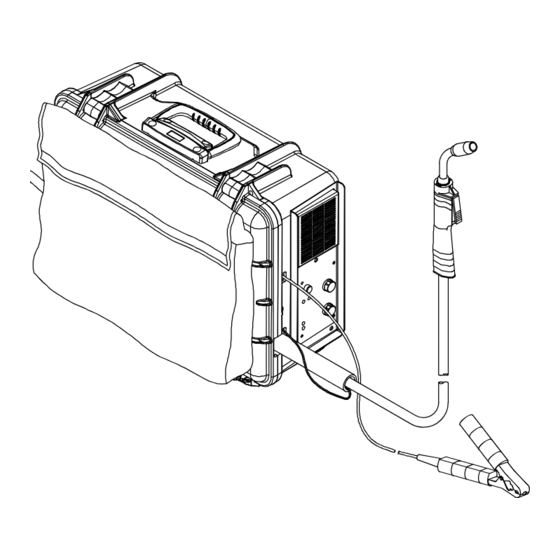
- Page 1 OM-1328 220 073C August 2004 Processes MIG (GMAW) Welding Flux Cored (FCAW) Welding Description Arc Welding Power Source And Wire Feeder Passport 180 And M-10 Gun Visit our website at www.MillerWelds.com...
- Page 2 We know you don’t have time to do it any other way. That’s why when Niels Miller first started building arc welders in 1929, he made sure his products offered long-lasting value and superior quality.
-
Page 3: Table Of Contents
TABLE OF CONTENTS SECTION 1 − SAFETY PRECAUTIONS - READ BEFORE USING ........1-1. - Page 4 TABLE OF CONTENTS SECTION 8 − MIG WELDING (GMAW) GUIDELINES ..........8-1.
-
Page 5: Section 1 − Safety Precautions - Read Before Using
SECTION 1 − SAFETY PRECAUTIONS - READ BEFORE USING som _8/03 1-1. Symbol Usage Means Warning! Watch Out! There are possible hazards with this procedure! The possible hazards are shown in the adjoining symbols. This group of symbols means Warning! Watch Out! possible Y Marks a special safety message. - Page 6 ARC RAYS can burn eyes and skin. BUILDUP OF GAS can injure or kill. D Shut off shielding gas supply when not in use. Arc rays from the welding process produce intense visible and invisible (ultraviolet and infrared) rays D Always ventilate confined spaces or use that can burn eyes and skin.
-
Page 7: Additional Symbols For Installation, Operation, And Maintenance
1-3. Additional Symbols For Installation, Operation, And Maintenance FIRE OR EXPLOSION hazard. MOVING PARTS can cause injury. D Do not install or place unit on, over, or near D Keep away from moving parts such as fans. combustible surfaces. D Keep all doors, panels, covers, and guards D Do not install unit near flammables. -
Page 8: Principal Safety Standards
1-5. Principal Safety Standards Safety in Welding, Cutting, and Allied Processes, ANSI Standard Z49.1, Boulevard, Rexdale, Ontario, Canada (phone: from American Welding Society, 550 N.W. LeJeune Rd, Miami FL 33126 800−463−6727 or in Toronto 416−747−4044, website: www.csa−in- (phone: 305-443-9353, website: www.aws.org). ternational.org). -
Page 9: Section 2 − Consignes De Sécurité − À Lire Avant Utilisation
SECTION 2 − CONSIGNES DE SÉCURITÉ − À LIRE AVANT UTILISATION som_fre 8/03 2-1. Signification des symboles Signifie « Mise en garde. Faire preuve de vigilance. » Cette procédure présente des risques identifiés par les symboles adjacents aux directives. Ce groupe de symboles signifie « Mise en garde. Faire preuve de vigi- lance. - Page 10 LES RAYONS DE L’ARC peuvent cau- LES ACCUMULATIONS DE GAZ peu- ser des brûlures oculaires et cuta- vent causer des blessures ou même nées. la mort. Le rayonnement de l’arc génère des rayons visibles et D Couper l’alimentation en gaz protecteur en cas de invisibles intenses (ultraviolets et infrarouges) suscep- non utilisation.
-
Page 11: Autres Symboles Relatifs À L'installation, Au Fonctionnement Et À L'entretien De L'appareil
2-3. Autres symboles relatifs à l’installation, au fonctionnement et à l’entretien de l’appareil. Risque D’INCENDIE OU D’EXPLO- LES ORGANES MOBILES peuvent SION causer des blessures. D Ne pas placer l’appareil sur une surface inflam- D Se tenir à l’écart des organes mobiles comme les mable, ni au−dessus ou à... -
Page 12: Principales Normes De Sécurité
2-4. Principales normes de sécurité Safety in Welding, Cutting, and Allied Processes, norme ANSI Z49.1, Rexdale, Rexdale (Ontario) Canada M9W 1R3 (téléphone : (800) de l’American Welding Society, 550 N.W. LeJeune Rd, Miami FL 33126 463−6727 ou à Toronto : (416) 747−4044, site Web : www.csa−interna- (téléphone : (305) 443−9353, site Web : www.aws.org). -
Page 13: Section 3 − Specifications
SECTION 3 − SPECIFICATIONS 3-1. Specifications Amperes Input Rated Maximum Input at Rated Load Weight Overall Welding Open-Circuit Amperage Range Voltage W/ Gun Dimensions Output, 60 Hz, Output Voltage DC Single-Phase 110 A @ 19.5 Volts DC, 20% Duty Cycle 30 −... -
Page 14: Duty Cycle And Overheating
3-3. Duty Cycle And Overheating Duty Cycle is percentage of 10 minutes that unit can weld at rated load without overheating. 115 VAC DUTY CYCLE If unit overheats, thermostat(s) opens, output stops, and cooling fan runs. Wait fifteen minutes for unit to cool. -
Page 15: Section 4 − Installation
SECTION 4 − INSTALLATION 4-1. Installing Work Clamp Insulating Sleeves Work Cable From Unit Slide one insulating sleeve over work cable before connecting to clamp. Work Clamp Screw Tools Needed: Work Clamp Tabs Bend tabs around work cable. Slide insulating sleeves over 3/8, 7/16 in... -
Page 16: Process/Polarity Table
4-3. Process/Polarity Table Cable Connections Process Process Polarity Polarity Cable To Gun Cable To Work GMAW − Solid wire with shield- DCEP − Reverse polarity Connect to positive (+) out- Connect to negative (−) output ing gas put terminal terminal FCAW −... -
Page 17: External Shielding Gas Supply
4-6. External Shielding Gas Supply Shielding Gas Connector The shielding gas connector allows connecting an external shielding gas supply to the unit. Internal/External Transfer Switch The Internal/External Transfer switch allows changing between the internal or external shielding gas supply. Place switch in the External Gas Supply position. -
Page 18: Electrical Service Guide For 230 Vac
4-7. Electrical Service Guide For 230 VAC Input Voltage Input Amperes At Rated Output Max Recommended Standard Fuse Or Circuit Breaker Rating In Amperes Circuit Breaker , Time-Delay Normal Operating Min Input Conductor Size In AWG Max Recommended Input Conductor Length In Feet (Meters) (20) Min Grounding Conductor Size In AWG Reference: 1999 National Electrical Code (NEC) -
Page 19: Selecting A Location And Connecting Input Power For 115 Vac Model
4-9. Selecting A Location And Connecting Input Power For 115 VAC Model Y Do Not cut off power cord connector and attempt to hard wire the power cord. The power cord connector and plugs are designed to work with pre-installed outlet receptacles. -
Page 20: Installing And Threading Welding Wire
4-10. Installing And Threading Welding Wire Installing Wire And Adjusting Hub Tension: Hold wire tightly to keep Retaining Nut it from unraveling. Hub Tension Adjustment Screw Remove retaining ring, and install spool so hub pin fits spool hole. Re- install retaining nut. Adjust tension screw so only a slight force is needed to turn spool. -
Page 21: Section 5 − Operation
Process Switch Pressing switch will change inductance to fit material type and operator’s preference. Power Switch Mild Stainless Steel Steel (CRISP) (SOFT) ARC CONTROL MILLER ELECTRIC MFG. CO., APPLETON, WI. USA Rear View 218 503-B / 803 809-A OM-1328 Page 17... -
Page 22: Weld Parameter Chart
5-2. Weld Parameter Chart OM-1328 Page 18... - Page 23 220 579-A OM-1328 Page 19...
-
Page 24: Section 6 − Maintenance &Troubleshooting
SECTION 6 − MAINTENANCE &TROUBLESHOOTING 6-1. Routine Maintenance Y Disconnect power before maintaining. 3 Months Replace Repair or Clean unreadable replace tighten weld labels. cracked terminals. weld cable. 6 Months Blow out or vacuum inside. During heavy service, clean monthly. 6-2. -
Page 25: Replacing Gun Contact Tip
6-3. Replacing Gun Contact Tip Y Turn power before replacing contact tip. Nozzle Contact Tip Cut off welding wire at contact tip. Remove nozzle. Remove contact tip and install new contact tip. Reinstall nozzle. Tools Needed: Ref. 802 399-A OM-1328 Page 21... -
Page 26: Cleaning Or Replacing Gun Liner
6-4. Cleaning Or Replacing Gun Liner Tools Needed: Y Disconnect gun from unit. 8 mm / 10 mm Head Tube Remove nozzle, contact tip, adapter, gas diffuser, and wire outlet guide. 8 mm 10 mm Remove liner. Lay gun cable out straight before installing new liner. -
Page 27: Replacing Switch And/Or Head Tube
6-5. Replacing Switch And/Or Head Tube Y Turn Off welding power source /wire feeder and disconnect gun. Remove handle locking nut. Slide handle. Remove switch housing. Install new switch and connect leads (polarity is not important). Reas- semble in reverse order. If replacing head tube, continue to end of figure. -
Page 28: Section 7 − Electrical Diagram
SECTION 7 − ELECTRICAL DIAGRAM Figure 7-1. Circuit Diagram OM-1328 Page 24... - Page 29 219 992-C OM-1328 Page 25...
-
Page 30: Section 8 − Mig Welding (Gmaw) Guidelines
SECTION 8 − MIG WELDING (GMAW) GUIDELINES 8-1. Typical MIG Process Connections Y Weld current can damage electronic parts in vehicles. This unit can operate for either the internal or Disconnect both battery cables before welding on a an external shielding gas supply. vehicle. -
Page 31: Typical Mig Process Control Settings
8-2. Typical MIG Process Control Settings NOTE These settings are guidelines only. Material and wire type, joint design, fitup, position, shielding gas, etc. affect settings. Test welds to be sure they comply to specifications. Material thickness determines weld 1/8 or parameters. -
Page 32: Holding And Positioning Welding Gun
8-3. Holding And Positioning Welding Gun NOTE Welding wire is energized when gun trigger is pressed. Before lowering helmet and pressing trigger, be sure wire is no more than 1/2 in (13 mm) past end of nozzle, and tip of wire is positioned correctly on seam. Hold Gun and Control Gun Trigger Workpiece... -
Page 33: Conditions That Affect Weld Bead Shape
8-4. Conditions That Affect Weld Bead Shape NOTE Weld bead shape depends on gun angle, direction of travel, electrode extension (stickout), travel speed, thickness of base metal, wire feed speed (weld current), and voltage. ° Push ° Perpendicular Drag GUN ANGLES AND WELD BEAD PROFILES Short Normal Long... -
Page 34: Gun Movement During Welding
8-5. Gun Movement During Welding NOTE Normally, a single stringer bead is satisfactory for most narrow groove weld joints; however, for wide groove weld joints or bridging across gaps, a weave bead or multiple stringer beads works better. Stringer Bead − Steady Movement Along Seam Weave Bead −... -
Page 35: Troubleshooting − Excessive Spatter
8-8. Troubleshooting − Excessive Spatter Excessive Spatter − scattering of molten metal particles that cool to solid form near weld bead. S-0636 Possible Causes Corrective Actions Wire feed speed too high. Select lower wire feed speed. Voltage too high. Select lower voltage range. Electrode extension (stickout) too long. -
Page 36: Troubleshooting − Excessive Penetration
8-10. Troubleshooting − Excessive Penetration Excessive Penetration − weld metal melting through base metal and hanging underneath weld. Excessive Penetration Good Penetration S-0639 Possible Causes Corrective Actions Excessive heat input. Select lower voltage range and reduce wire feed speed. Increase travel speed. Wrong polarity. -
Page 37: Troubleshooting − Burn-Through
8-13. Troubleshooting − Burn-Through Burn-Through − weld metal melting completely through base metal resulting in holes where no metal remains. S-0640 Possible Causes Corrective Actions Excessive heat input. Select lower voltage range and reduce wire feed speed. Increase and/or maintain steady travel speed. Wrong polarity. -
Page 38: Common Mig Shielding Gases
8-16. Common MIG Shielding Gases This is a general chart for common gases and where they are used. Many different combinations (mixtures) of shielding gases have been developed over the years. The most commonly used shielding gases are listed in the following table. - Page 39 Notes OM-1328 Page 35...
-
Page 40: Section 9 − Parts List
SECTION 9 − PARTS LIST Hardware is common and not available unless listed. 803 813-A Figure 9-1. Main Assembly OM-1328 Page 36... - Page 41 ....218 503 LABEL, nameplate MILLER PASSPORT 180 ..... .
- Page 42 Item Dia. Part Mkgs. Description Quantity Figure 9-1. Main Assembly (Continued) ....193 144 INSULATOR, output stud .........
- Page 43 203 565 Figure 9-2. Wire Feed Drive Assembly Item Dia. Part Mkgs. Description Quantity 203 565 Figure 9-2. Wire Feed Drive Assembly ....202 500 HOUSING, plastic drive motor .
- Page 44 802 388-A Figure 9-3. M-10 Gun OM-1328 Page 40...
- Page 45 Item Part Description Quantity Figure 9-3. M-10 Gun ....169 715 NOZZLE, slip type .500 orf flush ....... . . ♦087 299 .
- Page 46 Notes...
- Page 47 Effective January 1, 2003 (Equipment with a serial number preface of “LC” or newer) This limited warranty supersedes all previous Miller warranties and is exclusive with no other Warranty Questions? guarantees or warranties expressed or implied. Call LIMITED WARRANTY − Subject to the terms and conditions Induction Heating Coils and Blankets below, Miller Electric Mfg.
- Page 48 Distributor Address City State For Service Call 1-800-4-A-Miller or see our website at www.MillerWelds.com to locate a DISTRIBUTOR or SERVICE AGENCY near you. Always provide Model Name and Serial/Style Number. Contact your Distributor for: Welding Supplies and Consumables Options and Accessories...
Need help?
Do you have a question about the Passport 180 and is the answer not in the manual?
Questions and answers