SMA DATA MANAGER M Operating Manual
Hide thumbs
Also See for DATA MANAGER M:
- Operating manual (58 pages) ,
- Technical information (22 pages) ,
- Operating manual (84 pages)
Table of Contents
Advertisement
Quick Links
Advertisement
Table of Contents

Related Manuals for SMA DATA MANAGER M


Summary of Contents for SMA DATA MANAGER M
- Page 1 Operating manual SMA DATA MANAGER M ENGLISH EDMM-10-BE-en-27 | Version 2.7...
- Page 2 Important information SMA Solar Technology AG Important information Depending on availability, the product is or is not equipped with Wi-Fi functionality. The reason for this is the currently problematic semiconductor supply, caused by the COVID-19 pandemic. If the product is not equipped with Wi-Fi functionality, please use the standard Ethernet communication interface included for commissioning, configuration and integrating the product into a network.
- Page 3 Legal Provisions Legal Provisions The information contained in these documents is the property of SMA Solar Technology AG. No part of this document may be reproduced, stored in a retrieval system, or transmitted, in any form or by any means, be it electronic, mechanical, photographic, magnetic or otherwise, without the prior written permission of SMA Solar Technology AG.
- Page 4 Legal Provisions SMA Solar Technology AG Copyright © 2023 SMA Solar Technology AG. All rights reserved. EDMM-10-BE-en-27 Operating manual...
-
Page 5: Table Of Contents
Preparing the Connection Cable................29 Connecting Signal Source to Digital Input ............... 29 Connecting RS485 Devices..................31 Connecting the network..................... 33 Connecting the Voltage Supply ................34 Replacing SMA Com Gateway with RS485 Devices..........36 Commissioning ................. 38 Operating manual EDMM-10-BE-en-27... - Page 6 8.13 Fallback Behavior....................... 56 Firmware Update..............57 Updating the Product Firmware ................57 Updating the Firmware of Connected SMA Products ..........58 10 Troubleshooting ............... 60 11 Decommissioning the Product..........62 12 Technical Data ................63 13 Accessories ................65 14 Contact ..................
-
Page 7: Information On This Document
You will find the latest version of this document and further information on the product in PDF format and as eManual at www.SMA-Solar.com. You can also call up the eManual via the user interface of the product. Illustrations in this document are reduced to the essential information and may deviate from the real product. -
Page 8: Symbols In The Document
1 Information on this Document SMA Solar Technology AG NOTICE Indicates a situation which, if not avoided, can result in property damage. Symbols in the Document Icon Explanation Information that is important for a specific topic or goal, but is not safety-rele-... -
Page 9: Additional Information
System Controller" "WAGO-I/O-SYSTEM 750 with SMA DATA MANAGER M" Installation Manual "SMA DATA MANAGER M / SMA DATA MANAGER M Lite - Stor- Technical Information age of active power limitation and reactive power setpoint" "SMA DATA MANAGER M / SMA DATA MANAGER L - Fault ride- Technical Information through (FRT) behavior"... -
Page 10: Safety
SMA Data Manager M. This includes energy generators and loads, I/O systems and energy meters. The SMA Data Manager M is suited for systems with a maximum total PV or battery power of 2.5 MVA. In the process, the SMA Data Manager M is supporting communication with up to 50 devices such as PV inverters, battery inverters, energy meters and I/O systems. - Page 11 NOTICE Manipulation of system data in networks You can connect the supported SMA products to the Internet. When connected to the Internet, there is a risk that unauthorized users can access and manipulate the data of your system. • Set up a firewall.
- Page 12 • SMA Solar Technology AG recommends using an Internet flat rate with a monthly data volume of at least 3 GB for systems with up to 50 SMA products. • SMA Solar Technology AG recommends a data transfer rate of at least 10 Mbit/s for flat- rate surfing.
-
Page 13: Supported Products
If the data communication between the Data Manager and SMA products connected via SMA Speedwire is interrupted, the data will be retrieved subsequently for the time of the interruption. Data is retrieved with a maximum interruption period of 7 days. Existing data of newly connected SMA products will not be transmitted until the Data Manager is commissioned. - Page 14 Sensors (via connected SMA inverters): The following sensors that are connected to an SMA inverter are supported (for connection options see the inverter manual): • Irradiation sensors •...
- Page 15 • 1x EEBUS compatible charging station for electric vehicles (e.g. Audi e-tron charging system connect). The optional licensed function SMA Charge S is required for this. • 10 x SMA EV Charger Business (20 charging points) via Modbus TCP Operating manual...
-
Page 16: Scope Of Delivery
3 Scope of Delivery SMA Solar Technology AG Scope of Delivery Check the scope of delivery for completeness and any externally visible damage. Contact your distributor if the scope of delivery is incomplete or damaged. Figure 1: Components included in the scope of delivery... -
Page 17: Product Overview
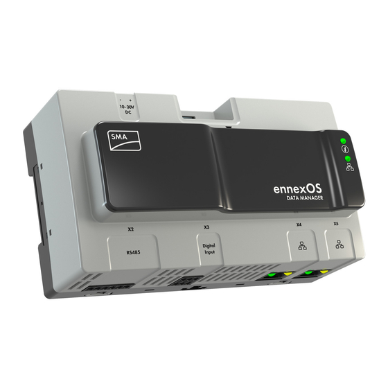
SMA Solar Technology AG 4 Product Overview Product Overview Product Description Figure 2: Design of the product Position Designation Press-out brackets for wall mounting Jack for connecting the RS485 devices Jack for the connection of digital signals Network ports with status LEDs for connecting to the network Type labels The product has two type labels. -
Page 18: Symbols On The Product
4 Product Overview SMA Solar Technology AG Position Designation System LED The system LED, together with the COM LED, indicates the operating state of the product (see Section 4.4, page 19). Function button USB 2.0 ports for manual updates Jack for connection of the voltage supply Also see: •... -
Page 19: Function Button
SMA Solar Technology AG 4 Product Overview Icon Explanation RCM (Regulatory Compliance Mark) The product complies with the requirements of the applicable Australian stan- dards. This equipment contains specified radio equipment that has been certified to the Technical Regulation Conformity Certification under the Radio Law. - Page 20 4 Product Overview SMA Solar Technology AG System LED COM LED Explanation No power supply or no boot up procedure. Glowing orange Glowing orange Boot up procedure started. Flashing green User interface is being loaded. Glowing green Glowing orange Communication is being started.
-
Page 21: Sunny Portal
The colors of the network port LEDs and what each color indicates are not standardized The colors used by SMA Solar Technology AG for the Link LED and the Activity LED and what each color indicates may be different to those used in third-party products. - Page 22 4 Product Overview SMA Solar Technology AG For more information on the current and future functions, see the product page at www.SMA- Solar.com (e.g. detailed descriptions of function or information on parameterization). User interface for configuration and monitoring The product is equipped as standard with an integrated webserver, which provides a user interface for configuring and monitoring the product.
- Page 23 FTP protocol to the FTP server without encryption. SMA Smart Connected SMA Smart Connected is the free monitoring of the product via the SMA Sunny Portal. Thanks to SMA Smart Connected, the operator and qualified person will be informed automatically and proactively about product events that occur.
- Page 24 4 Product Overview SMA Solar Technology AG SMA Smart Connected is activated during registration in Sunny Portal. In order to use SMA Smart Connected, it is necessary that the product is permanently connected to Sunny Portal and the data of the operator and qualified person is stored in Sunny Portal and up-to-date.
- Page 25 4 Product Overview SMA Charge S The product has the licensed function SMA Charge S. With SMA Charge S, electric vehicles (currently only Audi e-tron charging system connect) can be charged via the EEBUS interface. In this process, the electric vehicle is charged preferentially when the system produces sufficient solar power or the grid power is particularly favorable.
-
Page 26: Mounting
5 Mounting SMA Solar Technology AG Mounting Requirements for Mounting Requirements for the mounting location: WARNING Danger to life due to fire or explosion Despite careful construction, electrical devices can cause fires. This can result in death or serious injury. -
Page 27: Mounting The Product
SMA Solar Technology AG 5 Mounting Dimensions for mounting: 108 mm (4.25 in) ennexOS DATA MANAGER 162 mm (6.38 in) Figure 4: Dimensions for wall mounting (Dimensions in mm (in)) Recommended clearances: ☐ A clearance of 50 mm (2 in) must be observed above and below to other objects. - Page 28 5 Mounting SMA Solar Technology AG Procedure: 1. Place the product onto the DIN rail from above and hook it into place. ☑ The product snaps audibly into place. 2. Ensure that the product is securely in place. Mounting the Product on the Wall 1.
-
Page 29: Connection
Jack for connecting the RS485 devices Jack for the connection of digital signals Network port with status LEDs for connecting to the SMA Speedwire network Network port with status LEDs for connecting to the SMA Speedwire network Preparing the Connection Cable Always proceed as follows to prepare each connection cable for connection to multipole plugs. - Page 30 Voltage supply output With the fast-stop function, depending on the set inverter operating mode, inverters can be disconnected from the utility grid or enter into standby operation. For further information on SMA products with fast-stop function see manual of the SMA products.
-
Page 31: Connecting Rs485 Devices
SMA Solar Technology AG 6 Connection Circuitry overview: DATA MANAGER Ripple control receiver Fast-Stop Figure 7: Connection of a Ripple Control Receiver 1. Connect the connection cable to the digital signal source (see the manual from manufacturer). 2. Connect the connection cable to the supplied six-pole plug. For this, unlock the required terminal positions using a suitable tool and plug the conductors into these terminal positions. - Page 32 6 Connection SMA Solar Technology AG Plug assignment: Plug Position Assignment Data+ (D+) Not assigned Ground (GND) Data- (D-) Line termination (optional) Line termination (optional) Requirements: ☐ The same baud rate (1200 baud, 9600 baud or 19200 baud) must be set in all RS485 devices.
-
Page 33: Connecting The Network
SMA Solar Technology AG 6 Connection 7. If the product is at the end of the RS485 bus, install a jumper wire as a line terminator between pin 5 and pin 6 on the six-pole plug. 8. Plug the six-pole plug into the port X2 on the product. -
Page 34: Connecting The Voltage Supply
6 Connection SMA Solar Technology AG Procedure: 1. Plug the RJ45 plug of the network cable into the network port X4 or X5 until the RJ45 plug snaps into place. The assignment of the network cables to the ports is not relevant, as the ports constitute a switch function. - Page 35 SMA Solar Technology AG 6 Connection ☐ The cable must have at least two insulated conductors ☐ Maximum cable length: 3 m (9.8 ft) Plug assignment: Plug Position Assignment Input voltage 10 V DC to 30 V DC Ground (GND) Procedure: 1. Mount the power supply unit (see the manufacturer manual).
-
Page 36: Replacing Sma Com Gateway With Rs485 Devices
☑ The product starts operation (see Section 7, page 38). Replacing SMA Com Gateway with RS485 Devices The product can be used in existing systems with RS485 devices to include the system into the SMA infrastructure. The RS485 devices are included via RS485 interface of the product. The product replaces an existing SMA Com Gateway in the system. - Page 37 8. Connect all plugs to the product (see Section 6.1, page 29). 9. Commission the product (see Section 7.3, page 40). 10. If the SMA Com Gateway has been removed from a system with an existing SMA Data Manager, delete all connected devices via the SMA Data Manager's user interface and add them again.
-
Page 38: Commissioning
Fi access point is then activated for approx. 30 minutes. Once this period has expired, the Wi-Fi access point is deactivated automatically. 2. Search for Wi-Fi networks with your end device. 3. Select the SSID of the Data Manager https://SMA[serial number] in the list with the found WiFi networks. 4. Enter the Wi-Fi (WPA2-PSK) password. -
Page 39: Establishing A Connection Via Ethernet In The Local Network
• Data transmission: Port 443 (https/TLS) / ldm-devapi.sunnyportal.com • User interface: Port 443 (https/TLS) / ennexos.sunnyportal.com • SMA Webconnect 1.5 and SMA SPOT: Port 9524 (TCP) / wco.sunnyportal.com Requirements: ☐ The product must be connected to the local network via a network cable (e.g. via a router). -
Page 40: Commissioning The Product
7 Commissioning SMA Solar Technology AG ☐ The respective latest version of one of the following web browsers must be installed on the smart device: Chrome, Edge, Firefox or Safari. ☐ JavaScript must be enabled in the web browser of the smart device. -
Page 41: Registering In Sunny Portal
SMA Solar Technology AG 7 Commissioning Restart at different system time An NTP server must be available in the local network or via the Internet. If there is no NTP server available, the time set in the web browser is used as system time. If the difference between the time in the web browser and the system time is more than one minute, the time is synchronized and the product restarted. - Page 42 7 Commissioning SMA Solar Technology AG Procedure: 1. Call up the Internet address https://ennexOS.SunnyPortal.com in the web browser. 2. Register as a new user in Sunny Portal or log into Sunny Portal as an existing user. 3. Create a new system or add product to an existing system.
- Page 43 SMA Solar Technology AG 7 Commissioning Add product to an existing system Procedure: 1. Log into Sunny Portal. 2. Select system. 3. Select the menu Configuration. 4. Select [Device management] in the context menu. 5. Select the button. ☑ The system setup assistant opens.
-
Page 44: Operation
SMA Solar Technology AG Operation Design of the User Interface The user interface of the SMA product (e.g. SMA Data Manager) and the user interface of Sunny Portal are uniform. The product is configured and commissioned on site via the user interface of the product. -
Page 45: User Groups And User Rights
SMA Solar Technology AG 8 Operation Position Designation Description System information Displays the following information: • System time • IP Address • Firmware version • Serial number • Licenses • Redirecting to help pages Content area Displays the dashboard or content of the selected menu... - Page 46 8 Operation SMA Solar Technology AG Rights User group Administrator Installer User Creating and configuring system − − − groups Displaying system monitoring − − − Configuring system monitoring − − − Displaying configuration of system − − − monitoring Displaying user rights −...
-
Page 47: Configuring Limitation Of Active Power Feed-In
In the event of a communication failure between the product and the inverter, the inverter is reduced to an output power of 0% during fallback). For more information see the inverter manual at www.SMA-Solar.com. Requirements: ☐ The configuration for the active power limitation must be agreed upon with the responsible grid operator. -
Page 48: Configuring Reactive Power As A Function Of Grid Voltage
8 Operation SMA Solar Technology AG ☐ There must be an appropriate energy meter installed at the grid-connection point within the system. Procedure: 1. Log into the user interface of the Data Manager. 2. Select the menu item Grid management service in the menu Configuration. -
Page 49: Configuring Modbus Devices
SMA Solar Technology AG 8 Operation Requirements: ☐ There must be an appropriate energy meter installed at the grid-connection point within the system. Procedure: 1. Log into the user interface of the Data Manager. 2. Select the menu item Grid management service in the menu Configuration. -
Page 50: Configuring A System With Several Data Managers
8 Operation SMA Solar Technology AG 6. Select Create a new Modbus profile. 7. Fill out the entry fields and select [Save]. Registering a New Modbus Device and Assigning a Modbus Profile Requirement: ☐ The Modbus devices must be in operation and connected to the Data Manager. -
Page 51: Speedwire Encryption Of The System Communication
Speedwire encryption is used to encrypt system communication between all compatible Speedwire devices. In order to be able to use the Speedwire encryption in the system, all connected Speedwire devices, apart from the SMA Energy Meter, must support the SMA Speedwire Encrypted Communication function. -
Page 52: Switching Digital Outputs Based On Thresholds
4. Select SMA Speedwire devices and confirm with [Next]. ☑ All SMA Speedwire devices in the systems are searched for and displayed. 5. Enable SMA Speedwire encryption and select [Continue]. 6. Assign a new system password and select [Save]. -
Page 53: Activate Licensed Functions
The licensed functions are activated in the product's user interface. Requirements: ☐ The required licensed function is included in the product or has been purchased in the SMA online store under www.SMA-Onlineshop.com. ☐ The activation code received by e-mail is available. -
Page 54: Creating And Importing A Backup File
As soon as the product and all devices are in operation and your system is optimally configured, SMA Solar Technology AG recommends creating a backup file. If you replace your product or reset your existing product to the default settings, the backup file can be used to transfer configuration information. -
Page 55: Configuring Sunny Tripower Core2
☐ All devices in the local network must be in operation and connected to the product via an Internet router. ☐ The inverters must have the current firmware version in each case (see the inverter product page of the PV inverter at www.SMA-Solar.com). ☐ The country data set each valid must be set. Procedure: 1. -
Page 56: Fallback Behavior
Fallback behavior in reactive power mode The fallback behaviors for reactive power mode can be set more detailed than for active power mode (see technical information "SMA GRID GUARD 10.0 - Grid Management Services via Inverter and System Controller" at www.SMA-Solar.com). -
Page 57: Firmware Update
SMA Solar Technology AG 9 Firmware Update Firmware Update Updating the Product Firmware There are 2 ways to update the product firmware: • Enabling Automatic Firmware Update (recommended) • Updating the Firmware at the product via USB Flash Drive Enabling Automatic Firmware Update (recommended) •... -
Page 58: Updating The Firmware Of Connected Sma Products
Updating the firmware at the Data Manager via USB flash drive Firmware updates despite disabled automatic firmware update The firmware update of the USB flash drive is installed on connected SMA products even if the automatic firmware update function is disabled in the parameters. - Page 59 SMA Solar Technology AG 9 Firmware Update 5. In the Event monitor menu on the Data Manager user interface, check whether the firmware has been updated successfully. 6. Once the firmware has been successfully updated, pull the USB flash drive out of the Data Manager USB port.
-
Page 60: Troubleshooting
• Ensure that no more than permissible devices are in the system. The network configuration of the local network is incorrect. • Ensure that the network configuration is correct. SMA Solar Technology AG recommends automatic network configuration. The reaction time of some devices exceeds the device search time. - Page 61 • The firmware version must be later than the firmware version date via USB flash drive. installed on the SMA product. Ensure that you have downloaded the correct firmware version for your SMA product and update the firmware again.
-
Page 62: Decommissioning The Product
11 Decommissioning the Product SMA Solar Technology AG 11 Decommissioning the Product WARNING Danger to life due to electric shock Lethal voltages are present at the connection point of the utility grid. • Disconnect the connection point from the utility grid using the separator (e.g. miniature circuit breaker). -
Page 63: Technical Data
SunSpec Modbus devices Max. 20 devices I/O systems and meters Ethernet, 10/100 Mbit/s, Modbus TCP RS485 devices Modbus RTU (1200 baud, 9600 baud or 19200 baud) / SMA Data1 (1200 baud and 19200 baud) Connections Voltage supply 2-pole connection, MINI COMBICON Network (LAN) 2 x RJ45 switched, 10BaseT / 100BaseT 1 x USB 2.0, type A... - Page 64 12 Technical Data SMA Solar Technology AG Digital inputs Quantity 4 + 1 fast stop Input voltage 24 V DC Maximum cable length 30 m (98 ft) Equipment Warranty 2 years Certificates and approvals www.SMA-Solar.com EDMM-10-BE-en-27 Operating manual...
-
Page 65: Accessories
GmbH & Co. KG (2ETH, 1RS232/485) Not permitted in all countries (e.g. Japan). For information on whether an accessory is permitted in your country, visit the website of the SMA subsidiary of your country at www.SMA-Solar.com or contact your distributor. -
Page 66: Contact
14 Contact SMA Solar Technology AG 14 Contact If you have technical problems with our products, please contact the SMA Service Line. The following data is required in order to provide you with the necessary assistance: • Device type • Serial number •... -
Page 67: Eu Declaration Of Conformity
(L 174/88, June 8, 2011) and 2015/863/EU (L 137/10, March 31, 2015) (RoHS) SMA Solar Technology AG confirms herewith that the products described in this document are in compliance with the fundamental requirements and other relevant provisions of the aforementioned directives. More information on the availability of the entire declaration of conformity can be found at https://www.sma.de/en/ce-ukca. -
Page 68: Declaration Of Conformity
• The Restriction of the Use of Certain Hazardous Substances in Electrical and Electronic Equipment Regulations 2012 (SI 2012/3032) SMA Solar Technology AG confirms herewith that the products described in this document are in compliance with the fundamental requirements and other relevant provisions of the above- mentioned regulations. -
Page 69: Compliance Information
• Connect the equipment into an outlet on a circuit different from that to which the receiver is connected. • Consult the dealer or an experienced radio/TV technician for help. Changes or modifications made to this equipment not expressly approved by SMA Solar Technology AG may void the FCC authorization to operate this equipment. RF Exposure Statement Radiofrequency Radiation Exposure Information: This equipment complies with FCC radiation limits set forth for an uncontrolled environment. - Page 70 www.SMA-Solar.com...
Need help?
Do you have a question about the DATA MANAGER M and is the answer not in the manual?
Questions and answers