SMA DATA MANAGER L Operating Manual
Hide thumbs
Also See for DATA MANAGER L:
- Operating manual (60 pages) ,
- Technical information (22 pages)
Table of Contents
Advertisement
Quick Links
Advertisement
Table of Contents

Subscribe to Our Youtube Channel
Related Manuals for SMA DATA MANAGER L


Summary of Contents for SMA DATA MANAGER L
- Page 1 Operating manual SMA DATA MANAGER L ENGLISH EDML-10-BE-en-13 | Version 1.3...
- Page 2 SMA Solar Technology AG Legal Provisions The information contained in these documents is the property of SMA Solar Technology AG. No part of this document may be reproduced, stored in a retrieval system, or transmitted, in any form or by any means, be it electronic, mechanical, photographic, magnetic or otherwise, without the prior written permission of SMA Solar Technology AG.
-
Page 3: Table Of Contents
SMA Solar Technology AG Table of Contents Table of Contents Information on this Document..........Validity ........................Target Group......................Content and Structure of this Document ..............Levels of warning messages ..................Symbols in the Document ..................Typographical Elements in the Document.............. - Page 4 8.11 Deleting the Admin Account..................50 Firmware Update..............51 Updating the Product Firmware ................51 Updating the Firmware of Connected SMA Products ..........51 10 Troubleshooting ............... 53 11 Decommissioning the Product..........55 12 Technical Data ................57 13 Accessories ................59 14 Contact ..................
-
Page 5: Information On This Document
You will find the latest version of this document and further information on the product in PDF format and as eManual at www.SMA-Solar.com. You can also call up the eManual via the user interface of the product. Illustrations in this document are reduced to the essential information and may deviate from the real product. -
Page 6: Symbols In The Document
• Placeholder for variable • Parameter WCtlHz.Hz# components (e.g., parameter names) Designations in the Document Complete designation Designation in this document SMA Data Manager L Data Manager, product Additional Information For more information, please go to www.SMA-Solar.com. EDML-10-BE-en-13 Operating manual... - Page 7 "SMA DATA MANAGER M / SMA DATA MANAGER M Lite - Stor- Technical Information age of active power limitation and reactive power setpoint" "SMA DATA MANAGER M / SMA DATA MANAGER L - Fault ride- Technical Information through (FRT) behavior"...
-
Page 8: Safety
This document does not replace any regional, state, provincial, federal or national laws, regulations or standards that apply to the installation, electrical safety and use of the product. SMA Solar Technology AG assumes no responsibility for the compliance or non-compliance with such laws or codes in connection with the installation of the product. - Page 9 SMA Solar Technology AG 2 Safety DANGER Danger to life due to electric shock from touching an ungrounded product in the event of an error A product that is not grounded may be energized in the event of an error. Touching an ungrounded product results in death or serious injury due to electric shock in the event of an error.
- Page 10 NOTICE Manipulation of system data in networks You can connect the supported SMA products to the Internet. When connected to the Internet, there is a risk that unauthorized users can access and manipulate the data of your system. • Set up a firewall.
-
Page 11: Supported Products
• Sunny Portal powered by ennexOS • 1 SMA Inverter Manager with 1 Sunny Tripower Storage 60 • 1 SMA Inverter Manager with up to 42 Sunny Tripower 60 / Sunny Highpower Peak1 • SMA Hybrid Controller • SMA Data Manager M... - Page 12 • PFC200-BUNDLE of WAGO Kontakttechnik GmbH & Co. KG (see Section 13, page 59) Predefined SMA Modbus profiles The external I/O systems are controlled via Modbus profiles. A selection of predefined SMA Modbus profiles is available via the user interface and is regularly updated. In addition, user- defined Modbus profiles can be created, but they are only executed every 1000 ms.
-
Page 13: Scope Of Delivery
Figure 1: Components included in the scope of delivery Position Quantity Designation SMA Data Manager L Mounting plate for mounting on the DIN rail (TH 35-7.5) DIN rail mounting bracket for mounting on the DIN rail (TH 35-7.5) Wall mounting brackets for mounting on a wall... -
Page 14: Product Overview
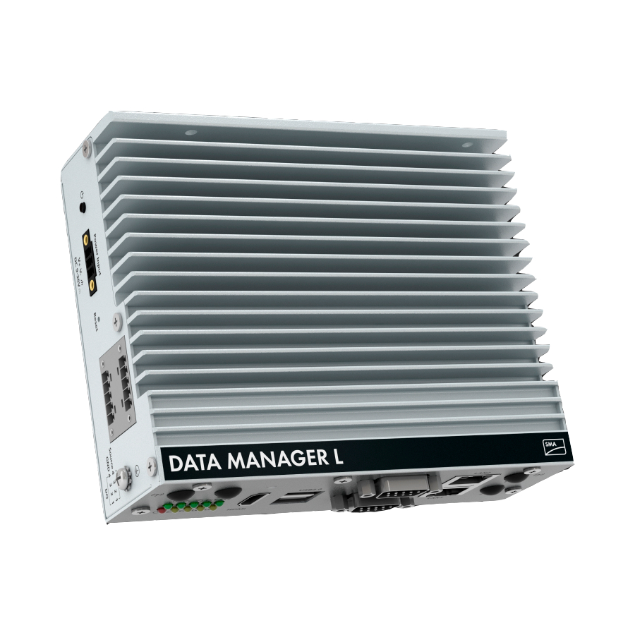
4 Product Overview SMA Solar Technology AG Product Overview Product Description P o w e r In p u t R e s e Figure 2: Design of the product Position Designation Operation button Starts the product Terminal for the voltage supply... -
Page 15: Symbols On The Product
SMA Solar Technology AG 4 Product Overview Position Designation Labels with internet address, registration ID (RID), identification key (PIC), de- vice key and MAC addresses of the Ethernet interfaces Type label The type label clearly identifies the product. The type label must remain per- manently attached to the product. -
Page 16: Led Signals
4 Product Overview SMA Solar Technology AG Icon Explanation Grounding conductor This symbol indicates the position for connecting a grounding conductor. Ground This symbol indicates the position for the connection to ground. WEEE designation Do not dispose of the product together with the household waste but in accor- dance with the disposal regulations for electronic waste applicable at the in- stallation site. -
Page 17: Sunny Portal
The colors of the network port LEDs and what each color indicates are not standardized The colors used by SMA Solar Technology AG for the Link LED and the Activity LED and what each color indicates may be different to those used in third-party products. - Page 18 (not part of the scope of delivery). The Modbus interface is deactivated by default and must be configured as needed. The Modbus interface of the supported SMA products is designed for industrial use – via SCADA systems, for example – and has the following tasks: •...
- Page 19 When specifications at the point of interconnection are actively controlled, this product enables the limitation the active power feed-in for the connected SMA inverters and of third-party inverters to 0% as long as these are connected via SunSpec Modbus and support this function.
- Page 20 4 Product Overview SMA Solar Technology AG Direct selling A direct marketer can use the product for remotely controlling the system via the built-in direct marketing interface. In this process, control signals of the direct marketer are transferred to the system.
-
Page 21: Mounting
SMA Solar Technology AG 5 Mounting Mounting Requirements for Mounting Requirements for the mounting location: WARNING Danger to life due to fire or explosion Despite careful construction, electrical devices can cause fires. This can result in death or serious injury. - Page 22 5 Mounting SMA Solar Technology AG Dimensions for mounting: 150 (5.91) 10.2 (0.4) 178 (7.01) Figure 3: Dimensions for wall mounting (Dimensions in mm (in)) Recommended clearances: If you maintain the recommended clearances, adequate heat dissipation will be ensured. Thus, you will prevent power reduction due to excessive temperature.
-
Page 23: Mounting The Product On The Din Rail
SMA Solar Technology AG 5 Mounting (2.8) (2.8) Figure 4: Recommended clearances (dimensions in mm (in)) Mounting the Product on the DIN Rail There are two options for mounting the product on the DIN rail: • Mounting the product with the back to the DIN rail •... - Page 24 5 Mounting SMA Solar Technology AG 2. Attach the DIN rail bracket to the mounting plate using six of the supplied screws. 3. Position the product onto the DIN rail from above and press on the bottom. ☑ The product snaps audibly into place.
-
Page 25: Mounting The Product On The Wall
SMA Solar Technology AG 5 Mounting 2. Position the product onto the DIN rail from above and press on the bottom. ☑ The product snaps audibly into place. 3. Ensure that the product is securely in place. Mounting the Product on the Wall Additionally required mounting material (not included in the scope of delivery): ☐... - Page 26 5 Mounting SMA Solar Technology AG 5. Insert the supplied screws through the holes and tighten. Use the washers if necessary. 6. Ensure that the product is securely in place. EDML-10-BE-en-13 Operating manual...
-
Page 27: Connection
SMA Solar Technology AG 6 Connection Connection Overview of the Connection Area U S B 2 P 2 R L A N S -2 3 U S B 3 2 / 4 2 P o w e r In U S B 2... -
Page 28: Connecting Signal Source To Digital Input
6 Connection SMA Solar Technology AG 2. Strip off 6 mm (0.24 in) of the conductor insulation from each of the required connection cable conductors. 3. Trim unneeded insulated conductors of the connection cable flush with the cable sheath. 4. If needed, push 1 bootlace ferrule onto 1 stripped insulated conductor as far as it will go and crimp using a crimping tool. -
Page 29: Connecting Rs485 Devices
RS485 devices via Modbus RTU. Additionally required mounting material (not included in the scope of delivery): ☐ RS232-RS485 adapter galvanic isolation (e.g. the TCC-100I-T from Moxa) For information on SMA products with fast-stop function see manual of the SMA products. Operating manual EDML-10-BE-en-13... -
Page 30: Connecting The Network
6 Connection SMA Solar Technology AG ☐ Serial RS232 extension cord with 1 DB-9 socket (9 pin contacts, D-sub) and 1 DB-9 plug (9 pin contacts, D-sub) Connector on the Position Assignment device 1 2 3 4 5 6 7 8 9 Procedure: 1. - Page 31 ☐ UV-resistant for outdoor use. Connect the network communication with internal nodes: SMA Solar Technology AG recommends using the network port LAN1 for the network communication with internal nodes (e.g. inverter and energy meter). Network port LAN1 is preconfigured with the static IP address 172.16.1.22.
-
Page 32: Connecting The Voltage Supply
SMA Solar Technology AG Connect the network communication with external nodes SMA Solar Technology AG recommends using the network port LAN2 for the network communication with external nodes (e.g. SCADA system, Sunny Portal). Network port LAN2 is preconfigured with the static IP address 192.168.100.22. - Page 33 SMA Solar Technology AG 6 Connection • 1 ring terminal lug M4 for grounding cable Requirements for the power supply unit: • Short-circuit current: < 8 A • Nominal output power: 18 W • DC output voltage: 9 V to 36 V • Compliance with the requirements on current sources with limited power in accordance with...
- Page 34 6 Connection SMA Solar Technology AG 5. Plug the 3-pole terminal block into the jack Power Input and attach. 6. Connect the AC connection cable to the power supply unit (see the manufacturer manual). WARNING Danger to life due to electric shock Lethal voltages are present at the connection point of the utility grid.
-
Page 35: Commissioning
Web browser signals a security vulnerability After the IP address has been entered, a message might appear indicating that the connection to the user interface of the product is not secure. SMA Solar Technology AG guarantees the security of the user interface. -
Page 36: Commissioning The Product
Web browser signals a security vulnerability After the IP address has been entered, a message might appear indicating that the connection to the user interface of the product is not secure. SMA Solar Technology AG guarantees the security of the user interface. -
Page 37: Registering In Sunny Portal
Sunny Portal. For this, all products of a system must be registered in Sunny Portal. The SMA Data Manager L only supports the Sunny Portal powered by ennexOS. Profiles for data communication Different profiles are available to control the intensity of data communication in the system. The profiles can be edited in the system properties at any time in Sunny Portal to adjust the... - Page 38 7 Commissioning SMA Solar Technology AG ☐ The operation LED must glow green. ☐ An active Internet connection must be established. Procedure: 1. Call up the Internet address https://ennexOS.SunnyPortal.com in the web browser. 2. Register as a new user in Sunny Portal or log into Sunny Portal as an existing user.
- Page 39 SMA Solar Technology AG 7 Commissioning 2. Select the menu Configuration. 3. Select [Create system] in the context menu. ☑ The system setup assistant opens. Add product to an existing system Procedure: 1. Log into Sunny Portal. 2. Select system. 3. Select the menu Configuration.
-
Page 40: Operation
SMA Solar Technology AG Operation Design of the User Interface The user interface of the SMA product (e.g. SMA Data Manager) and the user interface of Sunny Portal are uniform. The product is configured and commissioned on site via the user interface of the product. -
Page 41: User Groups And User Rights
SMA Solar Technology AG 8 Operation Position Designation Description System information Displays the following information: • System time • IP Address • Firmware version • Serial number • Licenses • Redirecting to help pages Content area Displays the dashboard or content of the selected menu... - Page 42 8 Operation SMA Solar Technology AG Rights User group Administrator Installer User Creating and configuring system − − − groups Displaying system monitoring − − − Configuring system monitoring − − − Displaying configuration of system − − − monitoring Displaying user rights −...
-
Page 43: Configuring Limitation Of Active Power Feed-In
In the event of a communication failure between the product and the inverter, the inverter is reduced to an output power of 0% during fallback). For more information see the inverter manual at www.SMA-Solar.com. Requirements: ☐ The configuration for the active power limitation must be agreed upon with the responsible grid operator. -
Page 44: Configuring Reactive Power As A Function Of Grid Voltage
8 Operation SMA Solar Technology AG ☐ There must be an appropriate energy meter installed at the grid-connection point within the system. Procedure: 1. Log into the user interface of the Data Manager. 2. Select the menu item Grid management service in the menu Configuration. -
Page 45: Configuring Modbus Devices
SMA Solar Technology AG 8 Operation Requirements: ☐ There must be an appropriate energy meter installed at the grid-connection point within the system. Procedure: 1. Log into the user interface of the Data Manager. 2. Select the menu item Grid management service in the menu Configuration. -
Page 46: Configuring A System With Several Data Managers
8 Operation SMA Solar Technology AG Registering a New Modbus Device and Assigning a Modbus Profile Requirement: ☐ The connected Modbus devices must be configured to send their setpoints in cyclic intervals (maximum cycle time: 1 minute; recommended cycle time: 1 second). -
Page 47: Speedwire Encryption Of The System Communication
Speedwire encryption is used to encrypt system communication between all compatible Speedwire devices. In order to be able to use the Speedwire encryption in the system, all connected Speedwire devices, apart from the SMA Energy Meter, must support the SMA Speedwire Encrypted Communication function. -
Page 48: Switching Digital Outputs Based On Thresholds
8 Operation SMA Solar Technology AG 5. Enable SMA Speedwire encryption and select [Continue]. 6. Assign a new system password and select [Save]. Switching Digital Outputs Based on Thresholds The digital outputs of connected I/O systems can be switched depending on measured values or states. -
Page 49: Creating And Importing A Backup File
As soon as the product and all devices are in operation and your system is optimally configured, SMA Solar Technology AG recommends creating a backup file. If you replace your product or reset your existing product to the default settings, the backup file can be used to transfer configuration information. -
Page 50: Resetting The Product
8 Operation SMA Solar Technology AG Procedure: 1. Select [Start restoration] on the login page of the user interface. ☑ The installation assistant will open. 2. Follow the installation assistant steps and, at the appropriate point, select the previously saved Ibd file. -
Page 51: Firmware Update
Updating the Firmware of Connected SMA Products Firmware update for connected SMA inverters When updating the firmware of connected SMA inverters, there are different procedures for string inverts with SMA Speedwire communication and central inverters with Modbus communication. - Page 52 4. Plug the USB flash drive into a Data Manager USB port. ☑ The firmware of the connected SMA products will be updated. The firmware update installs each SMA product at night and restarts at sunrise. This only affects the grid feed-in minimally.
-
Page 53: Troubleshooting
• Ensure that no more than permissible devices are in the system. The network configuration of the local network is incorrect. • Ensure that the network configuration is correct. SMA Solar Technology AG recommends automatic network configuration. The Data Manager user in- The firmware has been updated to a newer version. - Page 54 • The firmware version must be later than the firmware version date via USB flash drive. installed on the SMA product. Ensure that you have downloaded the correct firmware version for your SMA product and update the firmware again.
-
Page 55: Decommissioning The Product
SMA Solar Technology AG 11 Decommissioning the Product 11 Decommissioning the Product WARNING Danger to life due to electric shock Lethal voltages are present at the connection point of the utility grid. This can result in death or serious injury. - Page 56 11 Decommissioning the Product SMA Solar Technology AG 7. Set the released lock of the DIN rail bracket back to the starting position. To do this, use a suitable tool to press against the clamp in the opening of the lock.
-
Page 57: Technical Data
SMA Solar Technology AG 12 Technical Data 12 Technical Data Communication SMA devices Max. 200 devices • incl. I/O systems and power analyzers Max. 10 devices (e.g. Ethernet, Modbus TCP) Connections Voltage supply 3-pole terminal Network (LAN) 2 x 10/100/1000 Mbps (RJ45) - Page 58 12 Technical Data SMA Solar Technology AG Equipment Intel® Atom™ processor (Quad Core, 1.91 GHz) Data storage Solid State Disk (SSD), 128 GB Warranty 63 months from date of delivery (see SMA limited factory warranty) Certificates and approvals www.SMA-Solar.com EDML-10-BE-en-13 Operating manual...
-
Page 59: Accessories
GmbH & Co. KG (8DI, 8DO, 4AI, 4AO, 4RTD) Not permitted in all countries. For information on whether an accessory is permitted in your country, visit the website of the SMA subsidiary of your country at www.SMA-Solar.com or contact your distributor. Operating manual EDML-10-BE-en-13... -
Page 60: Contact
14 Contact SMA Solar Technology AG 14 Contact If you have technical problems with our products, please contact the SMA Service Line. The following data is required in order to provide you with the necessary assistance: • Device type • Serial number •... -
Page 61: Eu Declaration Of Conformity
(L 174/88, June 8, 2011) and 2015/863/EU (L 137/10, March 31, 2015) (RoHS) SMA Solar Technology AG confirms herewith that the products described in this document are in compliance with the fundamental requirements and other relevant provisions of the above- mentioned directives. The entire EU Declaration of Conformity can be found at www.SMA- Solar.com. -
Page 62: Declaration Of Conformity
• The Restriction of the Use of Certain Hazardous Substances in Electrical and Electronic Equipment Regulations 2012 (SI 2012/3032) SMA Solar Technology AG confirms herewith that the products described in this document are in compliance with the fundamental requirements and other relevant provisions of the above- mentioned regulations. -
Page 63: Compliance Information
Changes or modifications made to this equipment not expressly approved by SMA Solar Technology AG may void the FCC authorization to operate this equipment. - Page 64 www.SMA-Solar.com...
Need help?
Do you have a question about the DATA MANAGER L and is the answer not in the manual?
Questions and answers