
Related Manuals for SMA ennexOS SUNNY PORTAL


Summary of Contents for SMA ennexOS SUNNY PORTAL
- Page 1 Operating manual SMA DATA MANAGER M with SUNNY PORTAL powered by ennexOS x O S e n n e A G E R M A N D A T A S U N N Y B ENGLISH EDMM-10-BE-en-20 | Version 2.0...
- Page 2 SMA Solar Technology AG Legal Provisions The information contained in these documents is the property of SMA Solar Technology AG. No part of this document may be reproduced, stored in a retrieval system, or transmitted, in any form or by any means, be it electronic, mechanical, photographic, magnetic or otherwise, without the prior written permission of SMA Solar Technology AG.
-
Page 3: Table Of Contents
SMA Solar Technology AG Table of Contents Table of Contents Information on this Document..........Validity ........................Target Group......................Content and Structure of this Document ..............Levels of Warning Messages ..................Symbols in the Document ..................Typographies in the Document.................. Designation in the document .................. - Page 4 Configuring a System with several Data Managers..........43 Speedwire Encryption of the System Communication ..........43 Firmware Update ..............45 Updating the Product Firmware ................45 Updating the Firmware of Connected SMA Products ..........46 10 Troubleshooting................ 47 11 Technical Data ................49 12 Accessories ................51 13 Contact ..................
-
Page 5: Information On This Document
You will find the latest version of this document and further information on the product in PDF format and as eManual at www.SMA-Solar.com. You can also call up the eManual via the user interface of the product. Illustrations in this document are reduced to the essential information and may deviate from the real product. -
Page 6: Symbols In The Document
1 Information on this Document SMA Solar Technology AG NOTICE Indicates a situation which, if not avoided, can result in property damage. Symbols in the Document Symbol Explanation Information that is important for a specific topic or goal, but is not safety-rele-... -
Page 7: Additional Information
Additional Information Title and information content Type of information "Direct Marketing Interface" Technical information "SMA Modbus® Interface – SMA DATA MANAGER M" Technical Information "PUBLIC CYBER SECURITY - Guidelines for a Secure PV System Technical information Communication" "RS485 Cabling Plan"... -
Page 8: Safety
Safety Intended Use The SMA Data Manager M is a data logger that acts as a system gateway and energy manager. PV system components and PV systems are integrated together with energy generators and loads into the SMA infrastructure and I/O systems and meters via the Ethernet interface. In the process, the SMA Data Manager M is supporting communication with up to 50 devices such as PV inverters, battery inverters, energy meters and I/O systems. - Page 9 Manipulation of PV system data in Ethernet networks You can connect the supported SMA products to the Internet. When connected to the Internet, there is a risk that unauthorized users can access and manipulate the data of your PV system.
- Page 10 • SMA Solar Technology AG recommends using an Internet flat rate with a monthly data volume of at least 3 GB for systems with up to 50 SMA products. • SMA Solar Technology AG recommends a data transfer rate of at least 10 Mbit/s for flat- rate surfing.
-
Page 11: Supported Products
• Sunny Portal powered by ennexOS • 1 SMA Inverter Manager with 1 Sunny Tripower Storage 60 • 1 SMA Inverter Manager with up to 42 Sunny Tripower 60 / Sunny Highpower Peak1 Supported Products from Other Manufacturers Energy meters: •... - Page 12 2 Safety SMA Solar Technology AG Sensors (via connected SMA inverters): The following sensors that are connected to an SMA inverter are supported (for connection options see the inverter manual): • Irradiation sensors • Anemometers • Temperature sensors Signal receivers and digital and analog signal sources: •...
-
Page 13: Scope Of Delivery
SMA Solar Technology AG 3 Scope of Delivery Scope of Delivery Check the scope of delivery for completeness and any externally visible damage. Contact your distributor if the scope of delivery is incomplete or damaged. Figure 1: Components included in the scope of delivery... -
Page 14: Product Overview
The type label clearly identifies the product. You will require the information on the type label to use the product safely and when seeking customer sup- port from the SMA Service Line. You will find the following information on the type label: •... -
Page 15: Symbols On The Product
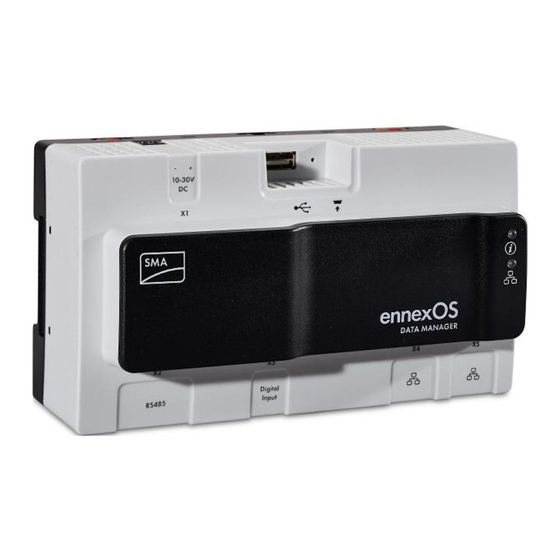
SMA Solar Technology AG 4 Product Overview Position Designation USB port for manual updates Jack for connecting the voltage supply Symbols on the Product Symbol Explanation Function button System LED Ethernet WEEE designation Do not dispose of the product together with the household waste but in accor- dance with the disposal regulations for electronic waste applicable at the in- stallation site. -
Page 16: Function Button
4 Product Overview SMA Solar Technology AG Symbol Explanation ANATEL The product complies with the requirements of the Brazilian standards for telecommunication. Este equipamento opera em caráter secundário, isto é, não tem direito a pro- teção contra interferência prejudicial, mesmo de estações do mesmo tipo, e não pode causar interferência a sistemas operando em caráter primário. - Page 17 The colors of the network port LEDs and what each color indicates are not standardized The colors used by SMA Solar Technology AG for the Link LED and the Activity LED and what each color indicates may be different to those used in third-party products.
-
Page 18: Sunny Portal
The product can be equipped or retrofitted with the following interfaces and functions: The availability of the functions depends on the product version and additional options purchased. For further information on current and future functions, refer to the product page at www.SMA- Solar.com. - Page 19 4 Product Overview SMA Speedwire The product is equipped with SMA Speedwire as standard. SMA Speedwire is a type of communication based on the Ethernet standard. SMA Speedwire is designed for a data transfer rate of 100 Mbps and enables optimum communication between Speedwire devices within systems.
- Page 20 SMA Smart Connected SMA Smart Connected is the free monitoring of the inverter via the SMA Sunny Portal. Thanks to SMA Smart Connected, the PV system operator and qualified person will be informed automatically and proactively about inverter events that occur.
- Page 21 The PV energy is therefore consumed exclusively at the place where it is generated. This product enables the limitation of the active power feed-in of the connected SMA inverters and inverters of other manufacturers, provided these are connected via SunSpec Modbus and support this function, to 0% with active closed-loop control of specifications at the grid-connection point.
-
Page 22: Mounting
5 Mounting SMA Solar Technology AG Mounting Requirements for Mounting Requirements for the Mounting Location: WARNING Danger to life due to fire or explosion Despite careful construction, electrical devices can cause fires. This can result in death or serious injury. -
Page 23: Mounting The Product
SMA Solar Technology AG 5 Mounting Dimensions for wall mounting: 108 mm (4.25 in) ennexOS DATA MANAGER 162 mm (6.38 in) Figure 4: Dimensions for wall mounting (dimensions in mm (in)) Mounting the product There are two options for mounting the product: •... - Page 24 5 Mounting SMA Solar Technology AG Mounting the Product on the Wall 1. Press the four brackets on the back side of the Product out from the inside. ☑ The brackets snap into place. 2. Mark the drill holes using the brackets as a template.
-
Page 25: Connection
Jack for connecting the RS485 devices Jack for the connection of digital signals Network port with status LEDs for connecting to the SMA Speedwire network Network port with status LEDs for connecting to the SMA Speedwire network Preparing the Connection Cable Always proceed as follows to prepare each connection cable for connection to multipole plugs. - Page 26 * With the fast stop function, depending on the set inverter operating mode, inverters can be disconnected from the utility grid or enter into standby operation. For further information on SMA products with fast stop function see manual of the SMA products.
-
Page 27: Connecting Rs485 Devices
SMA Solar Technology AG 6 Connection Circuitry overview: DATA MANAGER Ripple control receiver Fast-Stop Figure 7: Connection of a Ripple Control Receiver Procedure: 1. Connect the connection cable to the digital signal source (see the manual from manufacturer). 2. Connect the connection cable to the supplied six-pole plug. For this, unlock the required terminal positions using a suitable tool and plug the conductors into these terminal positions. - Page 28 6 Connection SMA Solar Technology AG Plug assignment: Plug Position Assignment Data+ (D+) Not assigned Ground (GND) Data- (D-) Line termination (optional) Line termination (optional) Procedure: 1. Dismantle 40 mm of the product end of the RS485 cable. 2. Strip the shielding to the same length as the cable sheath.
-
Page 29: Connecting The Voltage Supply
SMA Solar Technology AG 6 Connection 8. Plug the six-pole plug into the port X2 on the product. Connecting the Voltage Supply WARNING Danger to life due to electric shock Under fault conditions, when working on the power supply circuit there may be dangerous voltages present on the product. - Page 30 6 Connection SMA Solar Technology AG Requirements on the connection cable for connecting the power supply unit to the Data Manager: ☐ Core cross-section: 0.2 mm² to 1.5 mm² (32 AWG to 16 AWG) ☐ The cable must have at least two insulated conductors ☐ Maximum cable length: 3 m (9.8 ft)
- Page 31 SMA Solar Technology AG 6 Connection WARNING Danger to life due to electric shock Lethal voltages are present at the connection point of the utility grid. • Disconnect the connection point from voltage sources and ensure that the connection point is voltage-free.
-
Page 32: Commissioning
WLAN access point is deactivated automatically. 2. Search for WLAN networks with your end device. 3. Select the SSID of the Data Manager SMA[serial number] in the list with the found WLAN networks. 4. Enter the WLAN (WPA2-PSK) password. -
Page 33: Establishing A Connection Via Ethernet In The Local Network
Web browser signals a security vulnerability After the IP address has been entered, a message might appear indicating that the connection to the user interface of the product is not secure. SMA Solar Technology AG guarantees the security of the user interface. -
Page 34: Commissioning The Product
7 Commissioning SMA Solar Technology AG Commissioning the Product Once you have connected the product to the local network, the user interface login page opens. Figure 8: Login page of the user interface Requirements: ☐ All devices in the local network must be in operation and connected to the product via an Internet router. -
Page 35: Registering In Sunny Portal
SMA Solar Technology AG 7 Commissioning • Master and slave configuration • Meter configuration • Grid management services ☑ A successful commissioning is confirmed by a message. Registering in Sunny Portal Once you have carried out the commissioning on the user interface of the product, you can make further system configurations in Sunny Portal. - Page 36 7 Commissioning SMA Solar Technology AG Procedure: 1. Call up the Internet address https://ennexOS.SunnyPortal.com in the web browser. 2. Enter the e-mail address and the Sunny Portal password in the fields User and Password. 3. Select [Login]. Create new PV system The system setup assistant is a step-by-step guide to the processes required for user registration and the registration of your system in Sunny Portal...
-
Page 37: Operation
SMA Solar Technology AG 8 Operation Operation Design of the User Interface Figure 9: Design of the user interface (example) The user interface of the product and the user interface of Sunny Portal are uniform. The product is configured and commissioned on site via the user interface of the product. -
Page 38: User Groups And User Rights
8 Operation SMA Solar Technology AG Position Designation Description Configuration Offers depending on the number of connected devices the following functions: • Device configuration • System configuration Monitoring Displays depending on the selected device the following information on the current level and the superior levels: •... -
Page 39: Configuring Limitation Of Active Power Feed-In
SMA Solar Technology AG 8 Operation Rights User group Administrator Installer User Configuring user rights ✓ − − Configuring notifications ✓ ✓ − Displaying notification configuration ✓ ✓ − Displaying CO² widget ✓ ✓ ✓ Exporting data and parameters ✓... - Page 40 In the event of a communication failure between the product and the inverter, the inverter is reduced to an output power of 0% during fallback). For more information see the inverter manual at www.SMA-Solar.com. Requirements: ☐ The configuration for the active power limitation must be agreed upon with the responsible grid operator.
-
Page 41: Configuring Reactive Power As A Function Of Grid Voltage
SMA Solar Technology AG 8 Operation 10. Enter the value 100 in the field Active power gradient. 11. Enter the total PV array power in the field Total system power. 12. Click on [Save]. Configuring Reactive Power as a Function of Grid... -
Page 42: Configuring Modbus Devices
8 Operation SMA Solar Technology AG Configuring Modbus Devices Connected Modbus devices can be used, for example, as energy meters for generation and consumption data at the grid-connection point or for energy monitoring. For this, predefined Modbus profiles, user-created Modbus profiles or the SunSpec Modbus profile must be used. The Modbus profiles will then be assigned to the Modbus devices. -
Page 43: Configuring A System With Several Data Managers
Speedwire encryption is used to encrypt system communication between all compatible Speedwire devices. In order to be able to use the Speedwire encryption in the system, all connected Speedwire devices, apart from the SMA Energy Meter, must support the SMA Speedwire Encrypted Communication function. - Page 44 2. Select the Device registration menu item in the Configuration menu. 3. Select the button Configuration in the SMA Speedwire devices row. ☑ All SMA Speedwire devices in the systems are searched for and displayed. 4. Enable SMA Speedwire encryption and select [Continue].
-
Page 45: Firmware Update
SMA Solar Technology AG 9 Firmware Update Firmware Update Updating the Product Firmware There are two ways to update the product firmware: • Enabling Automatic Firmware Update (recommended) • Updating the Firmware at the product via USB Flash Drive Enabling Automatic Firmware Update (recommended) •... -
Page 46: Updating The Firmware Of Connected Sma Products
☐ USB flash drive at least in the version 2.0 ☐ The Data Manager must be in operation. ☐ The Data Manager must be connected to the connected SMA products via the local network. ☐ The connected SMA products must be in operation. -
Page 47: Troubleshooting
• Ensure that no more than permissible devices are in the system. The network configuration of the local network is incorrect. • Ensure that the network configuration is correct. SMA Solar Technology AG recommends automatic network configuration. The Data Manager user in- The firmware has been updated to a newer version. - Page 48 • The firmware version must be later than the firmware version date via USB flash drive. installed on the SMA product. Ensure that you have downloaded the correct firmware version for your SMA product and update the firmware again.
-
Page 49: Technical Data
SMA Solar Technology AG 11 Technical Data 11 Technical Data Communication SMA devices Max. 50 devices, Speedwire, 100 Mbit/s I/O systems and meters Ethernet, 10/100 Mbit/s, Modbus TCP RS485 devices Modbus RTU / 1200 baud to 19200 baud Connections Voltage supply... - Page 50 11 Technical Data SMA Solar Technology AG Input voltage 24 V Maximum cable length 30 m (98 ft) Equipment Warranty 2 years Certificates and approvals www.SMA-Solar.com EDMM-10-BE-en-20 Operating manual...
-
Page 51: Accessories
GmbH & Co. KG (2ETH, 1RS232/485) * Not permitted in all countries (e.g., Japan). For information on whether an accessory is permitted in your country, visit the website of your country's SMA subsidiary company at www.SMA-Solar.com or contact your distributor. -
Page 52: Contact
13 Contact SMA Solar Technology AG 13 Contact If you have technical problems with our products, please contact the SMA Service Line. The following data is required in order to provide you with the necessary assistance: • Device type • Serial number •... - Page 53 Toll free for Australia: 1800 SMA AUS SMA Online Service Center: (1800 762 287) www.SMA-Service.com International: +61 2 9491 4200 United Arab SMA Middle East LLC India SMA Solar India Pvt. Ltd. Emirates Abu Dhabi Mumbai +971 2234 6177 +91 22 61713888 SMA Online Service Center: www.SMA-Service.com ไทย Service Partner for String inverter: 대한민국...
- Page 54 13 Contact SMA Solar Technology AG United States SMA Solar Technology Toll free for USA and US Territories America LLC +1 877-MY-SMATech (+1 877-697-6283) Rocklin, CA International: +1 916 625-0870 Canada SMA Solar Technology Toll free for Canada / Sans frais pour le Canada : Canada Inc.
-
Page 55: Eu Declaration Of Conformity
(L 174/88, June 8, 2011) and 2015/863/EU (L 137/10, March 31, 2015) (RoHS) SMA Solar Technology AG confirms herewith that the products described in this document are in compliance with the fundamental requirements and other relevant provisions of the above- mentioned directives. The entire EU Declaration of Conformity can be found at www.SMA- Solar.com. -
Page 56: Compliance Information
• Connect the equipment into an outlet on a circuit different from that to which the receiver is connected. • Consult the dealer or an experienced radio/TV technician for help. Changes or modifications made to this equipment not expressly approved by SMA Solar Technology AG may void the FCC authorization to operate this equipment. RF Exposure Statement Radiofrequency Radiation Exposure Information: This equipment complies with FCC radiation limits set forth for an uncontrolled environment. - Page 58 www.SMA-Solar.com...
Need help?
Do you have a question about the ennexOS SUNNY PORTAL and is the answer not in the manual?
Questions and answers