
Related Manuals for Chipsee PPC-A53-070


Summary of Contents for Chipsee PPC-A53-070
- Page 1 Industrial PC PPC-A53-070 PN: CS10600-IMX8MP-070P Content can change at anytime, check documentation website for latest information. www.chipsee.com...
-
Page 2: Table Of Contents
Contents 1. PPC-A53-070 1.1. Product Overview 1.2. Ordering Options 1.2.1. Operating System 1.2.2. Optional Features 1.3. Hardware Features 1.4. Power Input 1.5. Touch Screen 1.6. Connectivity 1.6.1. RS232/RS485/CAN 1.6.2. GPIO Port 1.6.3. USB Connectors 1.6.4. LAN Connectors 1.6.5. WiFi & BT Module 1.6.6. -
Page 3: Ppc-A53-070
PPC-A53-070 PPC-A53-070 Front View Rear View Chipsee Page 3 of 22... -
Page 4: Product Overview
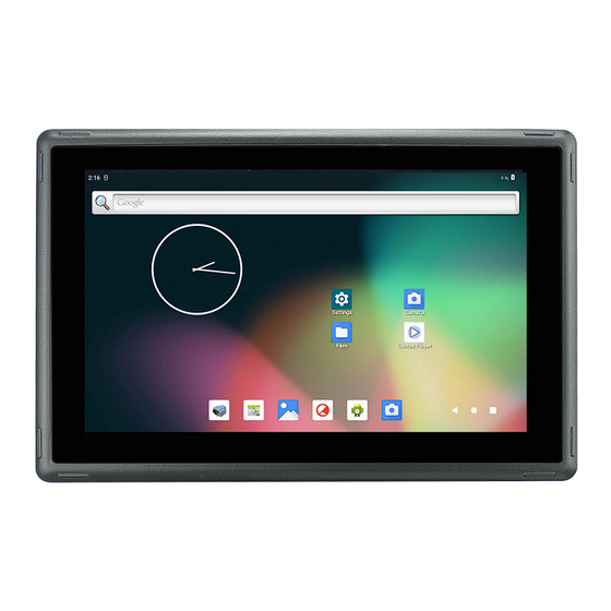
Side View 2 Product Overview ® The Cortex -A53 series PPC-A53-070 (PN: CS10600-IMX8MP-070P) is a high-quality industrial panel PC. It features a 7” 5-point capacitive touch screen with a resolution of 1024 x 600 pixels and a brightness of 400 cd/m . -
Page 5: Ordering Options
Installation on an industrial cabinet • Integration with the existing equipment The PPC-A53-070 Industrial Panel PC is based around the powerful i.MX8MP System on Chip (SoC), powered by the NXP i.MX8MP low-power processor which integrates a quad-core ® Cortex -A53 1.6GHz processor. -
Page 6: Optional Features
Software Documentation section provides a detailed instruction on how to install different OSes on your own. However, bear in mind that Chipsee can’t take the responsibility of inadequate installation procedure. If you “brick” your device, please contact Chipsee Technical Support at support@chipsee.com... -
Page 7: Power Input
Power Input The PPC-A53-070 Industrial Panel PC can be powered by a wide range of input voltages: From 6V to 36V DC. The power input connector is a 3-pin, 3.81mm terminal. The polarity and the pinout is shown in the figure below. - Page 8 PPC-A53-070 Power Input Power Input Note that the “+” sign represents the positive power input, it is printed at the casing and as a silk-screen on a PCB of the embedded version. The “-” terminal is shorted to the ground.
-
Page 9: Touch Screen
Use a high-quality Power Adapter Unit (PSU) with low EMR. You can also provide power from a battery. Make sure that the PPC-A53-070 Power Input connector (pin 3) is properly connected to the Power System Ground to provide sufficient EMI shielding and eliminate the problem entirely. -
Page 10: Rs232/Rs485/Can
PPC-A53-070 RS232/RS485/CAN RS232/RS485/CAN The serial communication interfaces (RS485, RS232, and CAN) are routed to a 16-pin 3.81mm terminal, as illustrated on the figure below. RS232, RS485 and CAN This product has 3 x CPU UART, 2 x USB UART by default, 6 x UART channels at most. The default configuration is 2 x RS232 and 3 x RS485, including 1 RS232 debug port. -
Page 11: Gpio Port
The 120Ω match resistor for the CAN bus is NOT mounted by default. GPIO Port The PPC-A53-070 Industrial Panel PC has a 10 Pin 3.81mm GPIO Connector, as shown in the figure below. The table below gives details about the definition of every Pin. - Page 12 PPC-A53-070 GPIO Port GPIO GPIO Pin Definition: Pin Number Definition Pin 1 Isolated Power Input3 Pin 2 Isolated Ground Input Pin 3 OUT1 Pin 4 OUT2 Pin 5 OUT3 Pin 6 OUT4 Pin 7 Pin 8 Pin 9 Pin 10 Table 83 GPIO Connector Pin-out If the isolation is not a requirement, it is possible to use a non-isolated PSU instead.
-
Page 13: Usb Connectors
PPC-A53-070 USB Connectors Isolated GPIO reduced schematic Attention • The GPIO has been Opt-Isolated and it uses the 24V Logic by default. • The 4 output channels can drive at most 500mA current on each channel. USB Connectors There are 2 x USB HOST and 1 x USB DEVICE (for flashing OS) ports onboard: 1 x USB 2.0 HOST, 1 x USB 3.0 HOST, 1 x USB Type-C , as shown in the figures below. - Page 14 PPC-A53-070 USB Connectors USB 2.0 HOST Port (embedded / enclosed PC version) USB 3.0 HOST Port (embedded / enclosed PC version) USB Type-C Port (embedded / enclosed PC version) Warning Be careful not to touch surrounding electronic components accidentally while plugging USB devices into the embedded IPC version.
-
Page 15: Lan Connectors
WiFi/BT module which supports BT/BLE 2.1/3.0/4.2, as well as 802.11ac/abgn 433Mbps 2.4/5.8 GHz Wireless LAN (WLAN). Figure 388: RTL8821CS WiFi/BT Module The PPC-A53-070 includes an SMA connector for an external WiFi/BT antenna, as illustrated in the figure below. Chipsee Page 15 of 22... -
Page 16: 4G/Lte Module
WiFi+BT Antenna SMA 4G/LTE Module The PPC-A53-070 Industrial Panel PC is equipped with a mini-PCIe connector that can connect a 4G/LTE module. The customer will also need a SIM Card Holder and a 4G/LTE Antenna Connector to ensure 4G/LTE works on the PPC-A53-070. SIM card does NOT support hot plug. -
Page 17: Tf Card Slot
TF Card Slot The PPC-A53-070 Industrial Panel PC features 1 x TF Card (micro SD) slot. TF Card can address up to 128GB of storage. TF (micro SD) Card Slot ... - Page 18 PPC-A53-070 Audio Connectors Audio Connector (enclosed PC version) The miniature 2W embedded speaker is handy for audio reproduction, the small buzzer can play alarm/notification sounds. 2W Micro Speaker and Buzzer Attention By plugging in the headphone cable, the internal speaker will be disabled automatically.
-
Page 19: Hdmi Connector
HDMI Connector PROG Button The PPC-A53-070 Industrial Panel PC has one button on the board marked as PROG, as shown in the figure below. It controls how the device will be booted. To boot from SD card, press and hold the PROG button, then connect the power supply, after a few seconds, you can see the system boot from SD card, then you may release the button. -
Page 20: Mounting Procedure
PPC-A53-070 Mounting Procedure PROG Button Mounting Procedure You can mount PPC-A53-070 with VESA mounting: 75 x 75 mm, 4 x M4 (6mm) screws. You can also mount PPC-A53-070 with panel mounting method. Attention Please make sure the display is not exposed to high pressure when mounting into an enclosure. -
Page 21: 3D Model
PPC-A53-070 3D Model Dimensions (PPC-A53-070) 3D Model PPC-A53-070 3D model can be viewed in the online doc in a web browser, if you are reading from the PDF version, please visit the online doc. Chipsee Page 21 of 22... -
Page 22: Disclaimer
If you cannot find the solution you’re looking for, feel free to contact us. Please email Chipsee Technical Support at support@chipsee.com, providing all relevant information. We value your queries and suggestions and are committed to providing you with the assistance you require.
Need help?
Do you have a question about the PPC-A53-070 and is the answer not in the manual?
Questions and answers