Table of Contents
Advertisement
Quick Links
INSTALLATION INSTRUCTIONS
&
MANUAL FOR MAINTENANCE
VIEW BELL
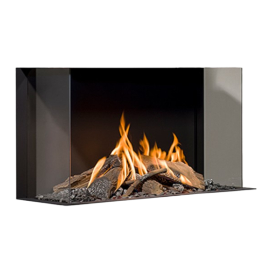
YORK 3 CF/LF
Gas fi res with closed combustion system
Bellfi res wishes you many cosy evenings with your new Bellfi res gas fi re
This document is an essential part of your gas fi re.
Read it carefully before installation and maintenance of the
gas fi re and keep it in a safe place!
Serial number:
Production date:
Advertisement
Table of Contents

Related Manuals for Bellfires VIEW BELL YORK 3 CF


Summary of Contents for Bellfires VIEW BELL YORK 3 CF
- Page 1 INSTALLATION INSTRUCTIONS & MANUAL FOR MAINTENANCE VIEW BELL YORK 3 CF/LF Gas fi res with closed combustion system Bellfi res wishes you many cosy evenings with your new Bellfi res gas fi re This document is an essential part of your gas fi re. Read it carefully before installation and maintenance of the gas fi...
- Page 3 Bellfi res English BELLFIRES GAS FIRE WITH CLOSED COMBUSTION SYSTEM: View Bell York 3 CF (Centre Fire) (VWBYK3 CF) View Bell York 3 LF (Line Fire) (VWBYK3 LF) Installation instructions...
- Page 4 1. INSTALLATION INSTRUCTIONS & MANUAL FOR MAINTENANCE AVAILABLE COMPONENTS CONCENTRIC FLUE-SYSTEMS FOR BELLFIRES GAS FIRES WITH CLOSED COMBUSTION SYSTEM 3. INSTRUCTIONS FOR USE & MANUAL DAILY MAINTENANCE 4. ‘PREMIUM FIRE’ SUPPLEMENT INSTALLATION INSTRUCTIONS & MAINTENANCE MANUAL (If the appliance is equipped with a ‘PREMIUM FIRE’...
-
Page 5: Table Of Contents
Bellfi res English CONTENTS Page 1. INSTALLATION INSTRUCTIONS .............. 2. MAINTENANCE ..................3. FAULTS ...................... 4. DISMANTLING / ASSEMBLING OF THE GLASS ........5. DIAGRAM ELECTRICITY AND GAS ............6. DIMENSIONS .................... 7. TECHNICAL DETAILS/REGULATIONS ............ 8. REPLACEMENT PARTS LIST ..............9. - Page 6 Bellfi res English Installation instructions...
-
Page 7: Installation Instructions
Bellfi res English INSTALLATION INSTRUCTIONS 1.1 GENERAL The gas fi re must be positioned and connected as a “room sealed system” (balance fl ue) appliance by a “Gas Safe Register” registered gas installation engineer in accordance with the following installation instructions, nationally and locally applicable regulations (see “Technical Details/ Regulations”... - Page 8 The permitted components for these systems are listed in instructions enclosed: AVAILABLE COMPONENTS CONCENTRIC FLUE-SYSTEMS FOR BELLFIRES GAS FIRES WITH CLOSED COMBUSTION SYSTEM. The guarantee on the appliance lapses if it is installed, fully or partially, with other components or a different fl...
- Page 9 Bellfi res English 1.3 INCLUDED Set documentation - Installation instructions & Manual for maintenance - Instructions for Concentric Components - Instructions for use & Manual daily maintenance Attributes - Ceramic log set, or marble pebbles white or marble pebbles grey N.B.
- Page 10 Ontop (Metaloterm US) concentric fl ue system(*) 3..Jeremias/STB - H-TWIN concentric fl ue system(*) 3..Jeremias - TWIN-GAS concentric fl ue system(*) (*) Please refer to the instructions enclosed: CONCENTRIC COMPONENTS SUITABLE FOR THE INSTALLATION OF A BELLFIRES GAS FIRE WITH CLOSED COMBUSTION Installation instructions...
- Page 11 Bellfi res English PREPARATION FOR INSTALLATION The following preparation must be carried out before the gas fi re can be installed. 1.5.1 Instructions for positioning the outlet 1.5.1.1 Positioning the outlet for correct operation: Roof-mounted outlet: >0.5 m Figure 1: Roof-mounted outlet This must be positioned at least 0.5 m from the roof edge;...
- Page 12 Bellfi res English 1.5.1.2. Positioning the outlet to avoid affecting the surrounding area All listed “distances” in this section are no more than guidelines. For the exact minimum “distances”, please consult your national and local directives. “Distance” = minimum distance required for positioning of the outlet to avoid adverse effects with respect to: A.
- Page 13 Bellfi res English Wall-mounted outlet: To avoid adverse effects Distance: outlet - A, B or C At walls in buildings with staggered Not permitted if A, B, or C are located heights. above the outlet. On a wall - general. (*) Above the outlet: >2 m Below the outlet:...
- Page 14 Bellfi res English GENERAL SERVICES 1.6.1 The Fume Channel/Combustion Air Intake The combined fume channel and combustion air intake requires one of the following concentric fl ue system confi gurations. Important: Due to the high temperature of the outer walls (approx.
- Page 15 Bellfi res English RIGID CONCENTRIC FLUE Ø100 mm - Ø150 mm SYSTEM CONNECTION POSSIBILITIES Appliance: Concentric fl ue connection Ø100-Ø150 mm or Ø130-Ø200 mm 10, 11, 12, 13 (100) Item descriptions: see 1.6.2 Assemble restriction plate: Appliance: Distance Y Concentric Concentric (min.-max.) connection...
- Page 16 Bellfi res English 14, 15 10, 11, 12, 13 (100) Item descriptions: see 1.6.2 Assemble restriction plate: Appliance: Distance Y Distance X (*) Distance Y Concentric Concentric (min.-max.) (min.-max.) (min.-max.) connection connection appliance appliance Ø100-Ø150 mm Ø130-Ø200 mm View Bell Width: 1.0 - 11.0 m 0 - 3.0 m...
- Page 17 Bellfi res English FLEXIBLE CONCENTRIC FLUE Ø100 mm - Ø150 mm SYSTEM CONNECTION POSSIBILITIES Appliance: Concentric fl ue connection Ø100-Ø150 mm or Ø130-Ø200 mm 10, 11, 12, 13 (100) Item descriptions: see 1.6.2 Assemble restriction plate: Appliance: Distance Y Concentric Concentric (min.-max.) connection...
- Page 18 Bellfi res English > 45° 10, 11, 12, 13 (100) Item descriptions: see 1.6.2 Assemble restriction plate: Appliance: Distance Y (*) Distance X (*) Distance Y Concentric Concentric (min.-max.) (min.-max.) (min.-max.) connection connection appliance appliance Ø100-Ø150 mm Ø130-Ø200 mm View Bell Width: 1.0 - 11.0 m 0 - 3.0 m...
- Page 19 Bellfi res English (100) Item descriptions: see 1.6.2 Assemble restriction plate: Appliance: Distance Y Concentric Concentric (min.-max.) connection connection appliance appliance Ø100-Ø150 mm Ø130-Ø200 mm Width: Width: 2.0 - 4.0 m B = 30 mm B = 65 mm View Bell York 3 Width: Width: 4.0 - 12.0 m...
- Page 20 Bellfi res English > 45° (100) Item descriptions: see 1.6.2 Assemble restriction plate: Appliance: Distance Y (*) Distance X (*) Distance Y Concentric Concentric (min.-max.) (min.-max.) (min.-max.) connection connection on appliance is on appliance is Ø100-Ø150 mm Ø130-Ø200 mm View Bell Width: 1.0 - 11.0 m 0 - 3.0 m...
- Page 21 Bellfi res English RIGID CONCENTRIC FLUE Ø100 mm - Ø150 mm SYSTEM CONNECTION POSSIBILITIES and with wall outlet Ø100 mm - Ø150 mm Appliance: Concentric fl ue connection Ø100-Ø150 mm or Ø130-Ø200 mm Wall 10, 11, 13 Termination Position (100) Item descriptions: see 1.6.2 Assemble restriction plate:...
- Page 22 Bellfi res English RIGID CONCENTRIC FLUE Ø130 mm - Ø200 mm SYSTEM CONNECTION POSSIBILITIES and with wall outlet Ø100 mm - Ø150 mm Appliance: Concentric fl ue connection Ø130-Ø200 mm Wall Termination 110, 111, 113 Position Item descriptions: see 1.6.2 Assemble restriction plate: Appliance: Distance Y...
- Page 23 Bellfi res English RIGID CONCENTRIC FLUE Ø130 mm - Ø200 mm SYSTEM CONNECTION POSSIBILITIES and with wall outlet Ø100 mm - Ø150 mm Appliance: Concentric fl ue connection Ø130-Ø200 mm Wall Termination 110, 111, 113 Position Item descriptions: see 1.6.2 Assemble restriction plate: Appliance: Distance Y...
- Page 24 Bellfi res English RIGID CONCENTRIC FLUE Ø130 mm - Ø200 mm SYSTEM CONNECTION POSSIBILITIES and with wall outlet Ø100 mm - Ø150 mm Appliance: Concentric fl ue connection Ø130-Ø200 mm Wall 110, 111, Termination Position 110, 113 110, 111, 113 Item descriptions: see 1.6.2 Assemble restriction plate:...
- Page 25 Bellfi res English RIGID CONCENTRIC FLUE Ø130 mm - Ø200 mm SYSTEM CONNECTION POSSIBILITIES and with wall outlet Ø130 mm - Ø200 mm Appliance: Concentric fl ue connection Ø130-Ø200 mm Wall Termination 110, 111, 113 Position Item descriptions: see 1.6.2 Assemble restriction plate: Appliance: Distance Y...
- Page 26 For the suitable and available components for concentric chimney systems, please consult the instruction book: “AVAILABLE COMPONENTS CONCENTRIC FLUE-SYSTEMS FOR BELLFIRES GAS FIRES WITH CLOSED COMBUSTION SYSTEM” • The room-sealed gas appliances have been approved in combination with the components of the concentric fl ue systems listed in the instruction book: ‘AVAILABLE COMPONENTS...
- Page 27 Bellfi res English 1.6.3 Gas connection Operation (gas regulator block (and receiver)) outside the appliance (in the operating unit): The gas connection is situated where the operating unit is built in near to the appliance. Use only gas piping with a minimum diameter of 1/2” and a shut-off valve. 1.6.4 Operating unit If the appliance is fi...
- Page 28 Bellfi res English Never position the appliance directly against the rear wall, but always place an nonfl ammable insulation plate, at least 12 mm thick, between the appliance and the rear wall, with free space on either side of 2 cm. (Total ± 5 cm.) The rear wall must be made of nonfl...
- Page 29 Bellfi res English Figure 16: Appliance installed in ventilated chimney breast Horizontal outlet of the fl ue gas exhaust /combustion air supply via the wall. Fitted with the options / accessories: • convection package (= convection casing and 1x convection set) •...
- Page 30 Bellfi res English Figure 17: Appliance installed in ventilated chimney breast Vertical outlet of the fl ue gas exhaust / combustion air supply via the roof. Fitted without convection package Inlet opening (appliance) convection air Inlet opening (grate) (chimney breast) convection air Natural convection in the chimney breast Outlet opening (grate) (chimney breast) convection air (2x)
- Page 31 Bellfi res English When fi tting the appliance, it can be levelled with the adjustable feet. These adjustable feet can be reached via the openings (4x), after removing the protective covers, in the corners of the fl oor of the combustion chamber. The fl...
- Page 32 Bellfi res English Position the gas supply pipe such that it can be easily mounted after installation. Because the control system is outside the appliance, the gas pipe must lead to where the operating unit (built in), the gas regulator block (and the receiver) assembly are fi...
- Page 33 Bellfi res English 1.7.1 Gas connection operating unit Important: During gas connection, take care not to twist the gas regulator block. Make sure that both the gas regulator block and the supply pipes are not subjected to stresses. The appliance is supplied with a built-in operating unit. Operating unit Frame with door (white)
- Page 34 Bellfi res English Important : Cement and chalk can damage the piping and can, in turn, lead to gas leaks. Disassembly and assembly of pipes and cables: If necessary for mounting, all pipe compression fi ttings and cable connectors can be temporarily disassembled.
- Page 35 Bellfi res English Pilot Gas Adjustment Screw Adjustment Screw (Pierce the housing with Maximum a small screwdriver) Burner pressure Motor-knob 8 Wire connecting Microswitch cable receiver Figure 20: Gas regulator block - Front Adjustment Screw Minimum Burner pressure Inlet Pressure Tap Outlet Pilot light Pressure Tap...
- Page 36 Bellfi res English Thermocouple Thermocouple voltage / current voltage / current Piezo cable OUT - connection (yellow) IN - connection (red) connection Connection 8 wire cable gas regulator block Connection for AUX: external operating Electrical (option) connection for gas valve 6 VDC Adapter “rear burner”...
- Page 37 Bellfi res English 1.7.2 Connecting the concentric fl ue Assemble the concentric fl ue system according to one of the examples in section 1.6.1, fi gure 4 to 14 inclusive. Make sure that all connections are completely gas tight. 1.7.2.1 Mounting the convection package (option) The convection package (option) consists of a convection casing and a convection set.
- Page 38 Bellfi res English Position the two fi tting boxes in the fi replace, at a minimum distance of 30 cm under the ceiling. Mount the other end of the aluminium pipes onto the fi tting boxes. To do this use the hose clamps supplied. When the fi replace is completely fi nished, mount the grilles onto the fi...
- Page 39 Bellfi res English Mantle iron (option). The optional mantle iron is intended for supporting the brickwork above the appliance. The mantle iron must rest on the brickwork on both sides so that upward building is possible. Level the mantle iron with the supplied bar set. Mantle iron in combination with the 10 cm frame (option).
- Page 40 Bellfi res English Fix the mantle iron to the rear wall with the bar set. Place the draw bars at an angle of about 60˚ (between the appliance and the wall). Level the mantle iron with the tension sleeves. 2 mm Ensure that the height between the mantle Keep a clearance of 2 mm between the iron and the underside of the glass is the...
- Page 41 Bellfi res English DO NOT COVER Do not cover the top side of the appliance with (built-in) materials. Once the fi replace has been fi nished, you can now, fi t the frame with the small door to the operating unit. After installation in a new fi...
- Page 42 Bellfi res English 1.7.4 Checking the gas connection After connection of the gas supply, check that all connections are completely gas tight using soapy water or a leak tester. 1.7.5 Positioning the ceramic log set or marble pebbles The appliance is supplied with a “Centre Fire” (CF) or “Line Fire” (LF) double burner: The appliance can be supplied with: •...
- Page 43 Bellfi res English 1.7.5.1 Ceramic log set + chips of wood + embers + vermiculite granules 1 Place the ceramic mat on the burner in such a way that the holes in the mat are in line with the burner openings. 2 Remove the embers carefully from their packaging and spread them evenly over the burner mat and the grate around the burner.
- Page 44 4 Place the logs on the burner: Natural gas-burner Propane / Butane-burner Appliance see fi gure: see fi gure: View Bell York 3 CF/LF Keep the burner orifi ces unblocked 5 Place the chips of wood around the burner. Installation instructions...
- Page 45 Bellfi res English Logs: Log no u Log no v Log no w Log no x Log no y Log no z Log no { Log no | Installation instructions...
- Page 46 Embers must not be placed next to the pilot light burner Keep the burner orifi ces unblocked! Figure 24: Log set View Bell York 3 CF/LF Position natural gas burner Embers must not be placed next to the pilot light burner Keep the burner orifi ces...
- Page 47 2 Spread the pebbles over the whole burner bed (burner and grid around the burner). Make sure that the pilot light remains free. View Bell York 3 CF/LF : see fi gure 26 and 27 IMPORTANT: Open area, in order...
- Page 48 Keep the burner orifi ces unblocked! Figure 27: Marble pebbles View Bell York 3 CF/LF Position natural gas and propane/butane burner Important: • Do not place any marble pebbles in front of the pilot light. Make sure that the pilot light can burn freely over the main burner.
- Page 49 Bellfi res English 1.7.6 Mounting fl ue gas restriction plate Depending on the length and shape of the concentric fl ue system and the chimney construction, you should, if indicated, fi t a restriction plate with a certain width (B) into the ceiling of the combustion chamber.
- Page 50 Bellfi res English The following restriction plates are supplied: Concentric fl ue connection appliance [Ø130 - 200 mm] [Ø100 - 150 mm] Restriction plate: Horizontal wall outlet Roof-mounted outlet Width: B = 30 mm Width: B = 40 mm B = 40 mm Width: B = 50 mm B = 50 mm...
- Page 51 Bellfi res English 1.7.7 Baffl e plate The appliance is factory supplied with a baffl e plate. This baffl e plate is located at the top of the combustion chamber, just before the connection with the concentric fl ue. The baffl e plate only remains on location, if a restriction plate needs to be mounted.
- Page 52 Bellfi res English Figure 30: Situation after removing the baffl e plate (No restriction plate allowed!) Baffl e plate has been removed. (The use of a restriction plate without a baffl e plate is not allowed.) Installation instructions...
- Page 53 Bellfi res English 1.7.8 Check overpressure hatches There are two overpressure hatches in the roof of the combustion chamber (front). Check that the hatches are loose, by lifting a little and carefully letting them come down again. Check if the packing under the hatches is sealed. Left overpressure hatch is in the correct Right overpressure hatch is in the correct position.
- Page 54 Bellfi res English 1.7.9 Checking the appliance following installation After installation, visually check the gas fl ame. When the fi re is ignited, the fl ames should be short and blue/yellow in colour. These fl ames should gradually increase in height and become more yellow.
-
Page 55: Maintenance
Bellfi res English MAINTENANCE 2.1 ANNUAL MAINTENANCE It is essential that the appliance, the complete concentric fl ue system (where possible) and the outlet are cleaned and inspected annually by a recognised fi tter/gas specialist. The safe operation of the appliance will thus remain guaranteed. - Page 56 Bellfi res English • Check the gas inlet-pressure (both when the appliance is off and when it burns at maximum) and the burner pressure. • Check if the overpressure hatches are correctly positioned and check if the packing seals properly under the hatches. •...
-
Page 57: Faults
Bellfi res English FAULTS POSSIBLE REASONS Possible reasons for the gas fi re going out are: • The concentric fl ue system is not installed according to one of the methods detailed in Paragraph 1.6. • An incorrect “fl ue gas restriction plate” is fi tted. •... -
Page 58: Dismantling / Assembling Of The Glass
Bellfi res English DISMANTLING / ASSEMBLING OF THE GLASS 4.1 VIEW BELL YORK 3 HIDDEN DOOR (10 cm frame (4 sided)) Dismantling of the glass: Place paperboard on the chimney breast, under the appliance. This helps prevent damage. • View Bell York 3 •... - Page 59 Bellfi res English • Remove the side panel on the right. • Remove the bottom panel, by pulling it gently to tilt forward and to remove. Prevent damage to the side glasses ! Installation instructions...
- Page 60 Bellfi res English • Unscrew the strip at the front under the • Using a screwdriver, slide the strip a glass. Screws only need a couple of little to the left. turns! • Remove the strip at the front. • Unscrew the long strip at the top a little and leave the strip in place.
- Page 61 Bellfi res English • Lift the glass carefully and pull it • Remove the glass by slanting it forward forwards a little at the bottom. a little at the bottom and taking it out. • The glasses at the sides can be removed in the same way as the front glass. Installation instructions...
- Page 62 Bellfi res English Compression spring position Side glass L/R Side glass compression spring L/R • Make sure that the compression • Side glass compression spring spring (Left and Right) stays in the (Left and Right). correct position. All fastening strips on the top side remain in position! Assembling of the glasses:...
-
Page 63: Diagram Electricity And Gas
Bellfi res English DIAGRAM ELECTRICITY AND GAS Double burner: : Perforation pattern “Centre Fire” double burner. : Perforation pattern “Line Fire” double burner. Gas pipe “Rear burner” “Rear burner” Gas pipe “Front burner” 8 Wire “Front burner” Motor- connecting knob cable Pilot light Thermocouple... -
Page 64: Dimensions
Bellfi res English DIMENSIONS VIEW BELL YORK 3 - Hidden Door Fitted with the option: Convection casing Installation instructions... - Page 65 Bellfi res English VIEW BELL YORK 3 - Hidden Door + 10 cm Frame Installation instructions...
- Page 66 Bellfi res English OPERATING UNIT Installation instructions...
-
Page 67: Technical Details/Regulations
• Gas safety installation and use regulations 1998 plus all relevant safety and building regulations concerning fi re installation • Document J: Combustion appliances and fuel storage systems Model : VIEW BELL YORK 3 CF (Centre Fire) : NATURAL GAS : BUTANE / PROPANE Country : GB;... - Page 68 Bellfi res English Model : VIEW BELL YORK 3 CF (Centre Fire) : NATURAL GAS : BUTANE / PROPANE Country : GB; Great Britain/IE; Ireland : GB; Great Britain/IE; Ireland Batteries remote control - Receiver : 4x 1.5V AA : 4x 1.5V AA - Hand-transmitter : 2x 1.5V AAA...
- Page 69 Bellfi res English Model : VIEW BELL YORK 3 LF (Line Fire) : NATURAL GAS : BUTANE / PROPANE Country : GB; Great Britain/IE; Ireland : GB; Great Britain/IE; Ireland Product identifi cation no : 0063CM3684 : 0063CM3684 Type of appliance under CE-norm Category of appliance natural gas G20 butane/propane G30/G31...
- Page 70 Bellfi res English Model : VIEW BELL YORK 3 LF (Line Fire) : NATURAL GAS : BUTANE / PROPANE Country : GB; Great Britain/IE; Ireland : GB; Great Britain/IE; Ireland Batteries remote control - Receiver : 4x 1.5V AA : 4x 1.5V AA - Hand-transmitter : 2x 1.5V AAA : 2x 1.5V AAA...
-
Page 71: Replacement Parts List
Bellfi res English REPLACEMENT PARTS LIST When requesting service or ordering replacement parts, please quote the model type and serial number. All parts listed in this manual may be ordered from a Bellfi res dealer. Article no Description 335118 Main burner “Centre Fire” 561 x 130 mm Natural gas G20 / Butane/Propane G30/G31 G20: 1x Ø10.0 mm front + 1x Ø10.0 mm rear... - Page 72 Bellfi res English Article no Description 321926 Thermocouple M10 - 1500 mm 333604 Thermocouple interrupter 310908 Pilot light set outer casing, Double fl ame 310909 Packing pilot light set outer casing 310910 Pilot light injector; Natural gas; no 36 310912 Pilot light injector;...
- Page 73 Appliance Log set Marble pebbles Marble pebbles set (white) set (grey) Embers with Vermiculite no 4 Log no Chips of Glow-effect black wood set Anthracite fi ltered 3 pieces Bag: 125 gr. Bag: 50 gr. Bag: 2.5 kg. Bag: 2.5 kg. xxxxxx 301863 332583...
-
Page 74: Disposal Of Packaging And Appliance
Bellfi res English DISPOSING OF PACKAGING AND APPLIANCE The appliance comes in recyclable packaging. This can include: • Cardboard • Wood • Plastic • Paper Such materials must be disposed of responsibly, in line with local regulations. Batteries should be disposed of as chemical waste. Batteries must be disposed of responsibly, in line with local regulations. - Page 76 Your Bellfi res dealer 01 - 200317 - 344486...
Need help?
Do you have a question about the VIEW BELL YORK 3 CF and is the answer not in the manual?
Questions and answers