Table of Contents
Advertisement
Quick Links
Advertisement
Table of Contents

Subscribe to Our Youtube Channel
Related Manuals for emitor COMBOLOOK Color


Summary of Contents for emitor COMBOLOOK Color
- Page 1 COMBOLOOK Color MANUAL...
-
Page 2: Table Of Contents
All information in this publication is based on the latest product information available at the time of printing. Emitor AB reserves the right to make changes at any time without notice and without incurring any obligation. No part of this publication may be reproduced without written permission. -
Page 3: Description
Contents: Contents: Contents: Contents: Page: Page: Page: Page: IIV. TV IIV. TV- - - - Functions (CATV) Functions (CATV) – – – – MAIN MENU MAIN MENU IIV. TV IIV. TV Functions (CATV) Functions (CATV) MAIN MENU MAIN MENU A. Full spectrum, span 13 and SPAN. B. -
Page 4: Operation
The COMBOLOOK COMBOLOOK Color is capable of working with the return-path signals in Cable-TV COMBOLOOK COMBOLOOK networks (5-65 MHz) (according to the EN50083 standard). The TV-part presents the full range spectrum of 2-900 MHz which can be zoomed to smaller segments of bandwidth (min 13 MHz-span). Accuracy (presentation of data): +1dB (at +20 C). -
Page 5: Connection And Power On
The instrument also has a RS232 (computer interface) connector for software revisions and transferring saved signal spectrums to your PC for storage/printing/e- mailing. RS232 Keyboard TV in Main Switch Tuning Knob SAT in Power Plug Audio Tune & Volume B. Connection and “Power On”: B. -
Page 6: Information Spectrum-Mode
Frequency-mode With the COMBOLOOK COMBOLOOK COMBOLOOK COMBOLOOK Color , the cursor-line is moved with the tuning knob. Move the cursor up/down by rotation (clock-wise/counter-clock wise). D. Information displayed on the screen in the Spectrum D. Information displayed on the screen in the Spectrum Mode: Mode: D. -
Page 7: Satv Functions
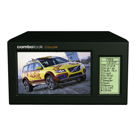
III. SATV Functions III. SATV Functions III. SATV Functions III. SATV Functions - - - - MAIN MENU MAIN MENU MAIN MENU MAIN MENU After the instrument is initially powered “ON”, and “SAT/TV function is selected, you will see the following display: 1. - Page 8 • The monitor displays, in the left upper corner, the so called, constellationdiagramme (QPSK). • To the right of it, four ”lock-parameters” and a time counter (that shows the “lock- time” on a bit-stream”) are shown. These "lock parameters" should be turned On (become white) and the clock should start counting as soon as a Digital transponder is found.
- Page 9 The picture above shows: • The selected channel - - - - in white in white in white. in white • Free to air channels – – – – in green. in green. in green. in green. • Coded channels – – – – in red. in red.
-
Page 10: Analogue Picture
* Press button nr 3 (Picture) to watch * Press button nr 3 (Picture) to watch the selected TV the selected TV- - - - channel channel * Press button nr 3 (Picture) to watch * Press button nr 3 (Picture) to watch the selected TV the selected TV channel... - Page 11 Example: Example: Example: Example: Measuring a specific frequency can be executed while in ”Picture Picture Picture- - - - Mode” Picture Mode” Mode” (dB-value is Mode” shown in the LCD-display). Other functions in the analogue Picture Other functions in the analogue Picture- - - - Mode: Mode: Other functions in the analogue Picture Other functions in the analogue Picture...
-
Page 12: Digital Measurement
TEXT EDITOR: TEXT EDITOR TEXT EDITOR TEXT EDITOR When the “Save” is selected; “TEXT EDITOR” appears on the monitor allowing you to name the memory-position (e.x: CNN). Rotate Knob to select the first letter (e.g.: “G”), then push the knob. Move to the next letter (e.g.: “a”), and so on. - Page 13 that will give the user a reference for the “concentration” of the data-stream. • Four ”lock-parameters” and a time counter (that shows the “lock-time” on a bit- stream”) are shown on the right of the CRT display. When these "lock parameters" are met, the circles on the left of each will fill-in (become white) and the “Lock Timer”...
- Page 14 Note in Digital Mode Digital Mode Digital Mode Digital Mode: • The constellation diagram is like a “shower of hail”. No signal will spread out the noise over the window. The better signal, the more concentrated the ”hailstorms” in the windows. •...
-
Page 15: Full Spectrum Max Zoom In
Text Text Text Text- - - - editor editor editor editor: When the channel (frequency) is saved, the Text-editor appears on the monitor which makes it possible to enter a name for that memory-position (ex. Digital). Use the knob to select the first letter (ex. D) and save it with the control-button. -
Page 16: Pol
• Move the cursor to any desired frequency (peak). Push the # 3 button (Span Min Span Min Span Min Span Min) on the keyboard. The instrument ”zooms in” to maximum for viewing the selected frequency (Span Min = 250 MHz bandwidth). Rotate the LNB so that either the Horizontal Horizontal or Vertical Vertical polarization will be in its... -
Page 17: Beeper
8. Beeper: 8. Beeper: 8. Beeper: 8. Beeper: The instruments variable-pitched tone/ ”beeper”- (signal strength) #7 Notice that the function works with a narrow bandwidth (one transponder) and not with the full bandwidth. To use this function: put the cursor on top of a selected”peak”... - Page 18 Note that 13/18V and 22 kHz on/off may be adjusted while in this mode with the ”0” and “#” buttons. 3. 3. 3. 3. Span Min Span Min Span Min Span Min – – – – Span Max Span Max Span Max Span Max This function is covered under the ”Main Menu”...
-
Page 19: Memory
10. Memory Memory Memory - - - - Storing Spectrum Memory Storing Spectrum Storing Spectrum Storing Spectrum- - - - Pictures Pictures Pictures Pictures. Color All spectrum-pictures may be stored in the COMBOLOOK COMBOLOOK COMBOLOOK COMBOLOOK This is useful for documentation and use in the future for recognition; or identification of a specific signal, through characteristic spectrum display. -
Page 20: Iiv. Tv
IV. TV TV- - - - functions (CATV) functions (CATV) – – – – Main Menu Main Menu IV. IV. functions (CATV) functions (CATV) Main Menu Main Menu only controlled by this button The tuning knob handles a few important functions ( and not via the LCD’s menu system ). -
Page 21: Max Hold
• Tune to any signal-peak and push button # 5 (Center Center Center Center). The instrument will center the cursor position on the selected frequency. • Push button # 3 (Span 900 Span 900) to index back to the original (full full) bandwidth. -
Page 22: Reference Cursor And Signal/Noise Ratio
C. C. C. C. Reference cursor and Signal Reference cursor and Signal Reference cursor and Signal Reference cursor and Signal- - - - to to to to- - - - Noise Ratio. Noise Ratio. Noise Ratio. Noise Ratio. Color The COMBOLOOK is capable of performing measurements of the Signal/Noise/ Picture-Carrier/Audio-Carrier ratio. -
Page 23: Memory
• Tune to the start frequency with the cursor (so the cursor stands in the beginning of the signal/transponder peak). • Push button #1 (Set strt Set strt Set strt) and a new (second) cursor appears on top of the earlier. Set strt •... -
Page 24: Picture, Tv, Text-Tv (Ceefax). ). ). )
To load previously saved data To load previously saved data: To load previously saved data To load previously saved data Main-Menu * Choose ”Memory Memory Memory”, button # 9 in the Memory * Next, select ”Spectrum Spectrum Spectrum” button # 1. Spectrum Memory-position * Locate the... -
Page 25: Attenuation– Automatic And Manual
The LCD screen also display the “TV-mode sub-menus”. Select “Text Text Text- - - - TV” (CEEFAX) Text TV” (CEEFAX) TV” (CEEFAX) TV” (CEEFAX) with button # 1. • If the selected TV-channel is transmitting Text Text- - - - TV (CEEFAX TV (CEEFAX);... -
Page 26: External Video/Audio
Select (using button # 1 thru 3) any of the following three versions Select (using button # 1 thru 3) any of the following three versions: Select (using button # 1 thru 3) any of the following three versions Select (using button # 1 thru 3) any of the following three versions •... -
Page 27: User Span
K. K. K. K. User Span (individual setup of frequency User Span (individual setup of frequency User Span (individual setup of frequency User Span (individual setup of frequency- - - - bands). bands). bands). bands). Color The COMBOLOOK COMBOLOOK COMBOLOOK COMBOLOOK (TV Component) initally powers “ON”... -
Page 28: Set (Personal Setup)
L. L. L. L. Set (Personal Set Set (Personal Set Set (Personal Set- - - - up): Set (Personal Set up): up): up): Color The COMBOLOOK COMBOLOOK may be set-up to individually-defined parameters for specific COMBOLOOK COMBOLOOK measurements. Main-Menu This kind of set-up is performed under the menu (# 6) “SET” SET”... -
Page 29: Maintenance
Button # 5: Button # 5: Button # 5: Button # 5: FM/AM mrkr: FM/AM mrkr: FM/AM mrkr: FM/AM mrkr: Choose between FM or AM marker. FM = Normal spectrum measuring. AM = Peak spectrum-measuring (preferable when measuring TV-signals due to the speed at which calculations are processed. Button # 6: Button # 6: ”SAT/TV”: ”SAT/TV”:... - Page 30 MicroSoft Word Print-outs may be done from a standard PC-printer. Manual for the software is attached with the CD, or may be downloaded from the manufacturer’s website at www.emitor.se For additional technical assistance in the operation of this meter, e-mail: support@emitor.se...
-
Page 31: Technical Specifications
COMBOLOOK COMBOLOOK Color Technical specification. Tech nical specification. COMBOLOOK COMBOLOOK Tech Tech nical specification. nical specification. Input frequency: 5-900 Mhz and 920-2150MHz. Sat-TV min level in: About 35 dBuV (noise). Sat-TV max level in: About 90 dBuV. CATV max input level, picture: 110 dByV.
Need help?
Do you have a question about the COMBOLOOK Color and is the answer not in the manual?
Questions and answers