Table of Contents
Advertisement
Quick Links
Advertisement
Table of Contents

Related Manuals for emitor SATLOOK Micro plus


Summary of Contents for emitor SATLOOK Micro plus
- Page 1 SATLOOK Micro + Owners Manual Version: 2.00...
-
Page 2: Table Of Contents
All information in this publication is based on the latest product information available at the time of printing. Emitor AB reserves the right to make changes at any time without notice and without incurring any obligation. No part of this publication may be reproduced without written permission. -
Page 3: Description
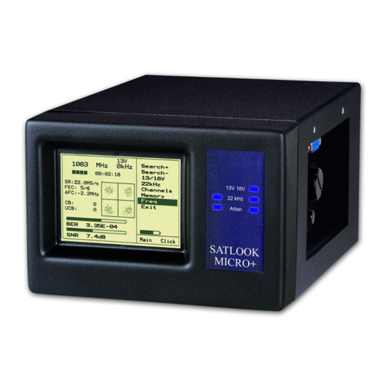
1 Description The SATLOOK MICRO + is a Swedish made SAT-TV instrument. The unit is made for exact alignment and adjustment of satellite-dishes. It is intended for professional use when high accuracy and precise information are needed. It´s easily operated without a lot of unnecessary buttons and knobs. The basic functions are easy to get a hold on and takes only a few minutes to learn. -
Page 4: On - Off
4. External power supply 220V/13.5V 5. 2 x Adaptor F-female/F-female 6. Owner's Manual 7. Program CD 8. Serial cable The instruments connections for coaxial- and power-cables are illustrated in the picture below. The big control knob has functions as e.g. tuning and moving in the meny-system. The two control buttons are used to turn on/off the instrument and to navigate in the menu- system. -
Page 5: Batterycheck
2.3 Batterycheck As the instrument has been stored for some time before transportation it is important to check the battery-condition. To do this, turn the meter on by pressing down the left (red) control button for about a second. When starting the instrument, the LCD and the blue LEDs turns on. The meter starts in Signalmeter-mode. -
Page 6: Beeper
Menu Signal bars Battery Left (red) controlbutton Right (black) controlbutton 3.1.1 Beeper If the loudspeaker (Beeper function) is switched on, it will present higher and higher tones as the signal level is getting better. 3.1.2 13/18V , 22 kHz and DiSEqC It is easy to set up 13/18V, 22 kHz on/off and DiSEqC-signals with help of the control knob and the control buttons. -
Page 7: Attenuator
3.1.4 Attenuator If the incoming signal is so strong that the bargraphs show max-values, reduce the incoming signal with the “Atten”-function. 3.1.5 Maxhold Shows the max-peakes of the signalvalues and will only change when higher values are received (makes it easier to align a dish and find max signal). 3.2 Digital Readout –... -
Page 8: Nit - Network Information Table
When performing Digital installations, please notice: • The constellation diagram is like ”a shower of hail”. No signal will spread out the noise over the window. The better signal, the more concentrated and focused ”hailstorms” in the windows. • SNR. The signal/noise ratio should be as high as possible. A good signal should have at least 8.0 dB S/N-ratio. -
Page 9: Satellite-Identification / Memory Positions/ Transfer Of Transponder Information To Pc
3.4 Satellite-Identification / Memory positions/ Transfer of transponder information to PC SATLOOK Micro + is preset with transponder info for the following satellites: Astra 28 (3 transponders) Astra 19 (3 transponders) Hotbird (3 transponders) Eutelsat 7 (3 transponders) Sirius (3 transponders) Thor (3 transponders) Hellas... -
Page 10: Setup
Press the button “Get data from SATLOOK Micro” and this will start the transfer of data. When the transfer is done it will appear a window on the screen for saving this data in a file on the PC. Disconnect the instrument and connect the SATLOOK Micro + that the transponder information should be transferred to. -
Page 11: Maintenance
4 Maintenance The instrument is equipped with a rechargeable NiMh-battery and it is important that the battery is maintained. Recharging should be done with the enclosed car-adaptor or the external power supply, 12v, 2 Amp, center-pin -plus and chassi -earth. Note, do not use other methods. -
Page 12: Technical Specification
5 Technical specification Input frequency: 920-2150MHz. Input level: 35-100 dBuV. Input/output impedance: 75 Ohm, F-connectors. Measuring method (Analog): - Signal presentation on LCD display in form of thermometer scales. - Pitch-tone, highest tone on loudspeaker. Measuring method (Digital): - BER (bit error rate) - S/N (signal/noise-ratio) - Constellation (QPSK) Max-level:...
Need help?
Do you have a question about the SATLOOK Micro plus and is the answer not in the manual?
Questions and answers