
Related Manuals for DEC VAX 4000 300


Summary of Contents for DEC VAX 4000 300
- Page 1 VAX 4000 Model 300 Operation Order Number EK–336AC–OP–003 Digital Equipment Corporation Maynard, Massachusetts...
- Page 2 The following are trademarks of Digital Equipment Corporation: CompacTape, CX, DDCMP, DEC, DECconnect, DECdirect, DECnet, DECscan, DECserver, DECUS, DECwindows, DELNI, DEMPR, DESQA, DESTA, DSRVB, DSSI, IVAX, KDA, KLESI, KRQ50, MicroVAX, MSCP, Q-bus, Q22-bus, RA, RQDX, RV20, SA, SDI, ThinWire, TK, TMSCP, TQK, TS05, TU, VAX, VAX 4000, VAXcluster, VAX DOCUMENT, VAXELN, VAXlab, VAXserver, VMS, VT, and the DIGITAL logo.
-
Page 3: Table Of Contents
Contents Preface Chapter 1 System Overview Front View and Physical Description ....1–1 1.1.1 BA440 Enclosure ....... . 1–6 1.1.1.1 Mass Storage Shelf . - Page 4 Chapter 2 Operating the System Before You Operate the System ..... . . 2–1 Switch Settings ........2–1 2.2.1 Normal Operation .
- Page 5 3.1.3.6 Removing a Tape Cartridge ..... . 3–27 3.1.3.7 Summary of TK70 Tape Drive Controls and Indicator Lights ........3–29 3.1.4 TLZ04 Tape Drive .
- Page 6 B.3.6 Exiting the DUP Server Utility ..... B–14 Appendix C Backup Procedures Overview of Standalone BACKUP ..... C–1 C.1.1 Installing Standalone BACKUP on the System Disk .
- Page 7 Figures 1–1 VAX 4000 System ........1–2 1–2 Key Positions .
- Page 8 3–16 Inserting the Head Cleaning Cassette ....3–37 B–1 VMS Operating System Requires Unique Unit Numbers for DSSI Devices ........B–4 B–2 Sample DSSI Busses for an Expanded VAX 4000 Model 300...
-
Page 9: Preface
Preface This manual describes how to use VAX 4000 Model 300 timesharing and VAXserver 4000 Model 300 server systems. The hardware and software for each of these systems differs slightly, according to the function of the system. The VAX 4000 is a multiuser system that uses the VMS operating system. - Page 10 Conventions The following conventions are used in this manual: Convention Meaning A symbol denoting a terminal key used in text and examples in this book. For example, indicates that you press the Break key on your terminal Break keypad. indicates that you press the Return key on your terminal Return keypad.
-
Page 11: Chapter 1 System Overview
Chapter 1 System Overview VAX 4000 systems house all components in a BA440 enclosure. This enclosure is a free-standing pedestal that houses the following: • Card cage • System controls • Central processing unit (CPU) module • Memory modules • Communications controller modules •... -
Page 12: Vax 4000 System
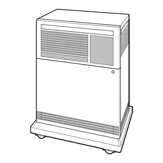
Figure 1–1: VAX 4000 System MLO-004032 A three-position rotary lock allows you to lock both the upper and lower doors, or to lock just the lower door. Opening the upper door allows you to access the controls for the RF-series Integrated Storage Elements (ISEs), tape drive, and the System Control Panel (SCP). -
Page 13: Key Positions
Figure 1–2 shows the three key positions and the controls accessible in each position. Figure 1–2: Key Positions Door Handle Rotary Key Lock Top Key Position: Access to SCP, ISEs, and Tape Drive Controls and Indicators (Upper Door) Middle Key Position: No Access to Controls Bottom Key Position: Access to Power Switch;... -
Page 14: Upper Door Opened
Figure 1–3 shows the system with the upper portion of the door opened. Figure 1–3: Upper Door Opened Top Key Position MLO-004034 1–4 VAX 4000 Model 300 Operation... -
Page 15: Entire Door Opened
Figure 1–4 shows the system with the entire door opened. Figure 1–4: Entire Door Opened Bottom Key Position MLO-004035 The next section describes the BA440 enclosure, which is exposed when you open the entire door. System Overview 1–5... -
Page 16: Ba440 Enclosure
1.1.1 BA440 Enclosure Opening the front door enables you to access the components housed in the BA440 enclosure. Figure 1–5 shows a typical configuration. The BA440 enclosure can contain the following: • Mass storage — TF85, TK70, or TLZ04 tape drive and up to three RF- series Integrated Storage Elements (ISEs), or four RF-series ISEs and no tape drive All VAX 4000 systems contain the following:... -
Page 17: Front View Of The Ba440 Enclosure
Figure 1–5: Front View of the BA440 Enclosure Integrated Storage Elements (ISEs) Tape Drive System Control Panel (SCP) Power Supply Console Module Fans Card Cage MLO-004016 System Overview 1–7... -
Page 18: Mass Storage Shelf
1.1.1.1 Mass Storage Shelf The mass storage shelf extends across the top of the enclosure. The shelf contains a system control panel (SCP), tape drive, and up to three RF-series ISEs (tapeless systems can have up to four RF-series ISEs). Each ISE has its own panel with controls and indicators. - Page 19 return it to the out position. When the Halt button is returned to the out position, the console mode prompt >>> is displayed on the console terminal screen. Now you can enter console commands. If you inadvertently press the Halt button, type ‘‘c ’’...
-
Page 20: Card Cage
1.1.1.2 Card Cage The modules in your system are mounted in a 12-slot card cage under the mass storage shelf, as shown in Figure 1–7. Figure 1–7: Card Cage Slots 12 - 6 Slots 5 - 1 Baud 300___________0 600___________1 1200__________2 2400__________3 4800__________4... - Page 21 • To maintain air flow integrity CAUTION: Do not operate the system without Digital-supplied module covers. The covers are required to protect the equipment and to meet international regulatory standards. Do not substitute other module covers as they may not meet the required specifications. Operating the system without the module covers has the following consequences: •...
-
Page 22: Console Module Controls And Connectors
Figure 1–8: Console Module Controls and Connectors Console Module Power-Up Mode Switch Modified Modular Jack Baud Rate Baud 300___________0 600___________1 Select Switch 1200__________2 Break Enable/ 2400__________3 4800__________4 9600__________5 Disable Switch 19200_________6 38400_________7 Bus 0 Bus Node LED Display Bus 1 ID Plugs Ethernet Connector... - Page 23 Run Mode (in the middle position, indicated by an arrow) is the normal operating setting. Loop Back Test Mode (in the bottom position, indicated by a T in a circle) causes the system to run loopback tests on the console serial line at power-up. This setting requires special loopback connectors and is for Digital Customer Services use only.
-
Page 24: Dssi Connector (Dssi Bus 0)
CPU. These plugs are configured at the factory. For single-host systems, Bus 0 is identified as bus node 6, bus 1 is identified as bus node 7; for dual-host systems, both busses on the first host are identified as bus node 7, and both busses on the second host are identified as bus node 6. -
Page 25: Power Supply Controls And Indicators
Figure 1–9: Connector for DSSI Bus 0 DSSI Bus 0 MLO-004039 1.1.1.5 Power Supply Controls and Indicators To the right of the card cage is the power supply. The power supply provides power to the mass storage devices, the modules installed in the card cage, and the fans. -
Page 26: Power Supply Controls And Indicators
Figure 1–10 shows the controls and indicators on the power supply. Figure 1–10: Power Supply Controls and Indicators Power Switch AC Present Indicator DC OK Indicator Fan Failure Indicator Over Temperature Condition Indicator Power Bus Connectors Power Cable Connector MLO-004040 The controls and indicator lights function as follows: Power switch —... - Page 27 input of the power supply. If the AC Present indicator does not light when the power switch is set to on, refer to your VAX 4000 Troubleshooting and Diagnostics manual. DC OK — When the green DC OK indicator is lit, the power supply voltages are within the correct operating range.
-
Page 28: Fans
signal is passed along, using the secondary in and out connectors as shown in Figure 1–11. The secondary out (SO) connector sends the signal down the power bus for configurations of more than one expander. Figure 1–11: Sample Power Bus Configuration System Expander 1 Expander 2... -
Page 29: Functional Description Of Base System
NOTE: The fan speed control can be set so that the fans will run at their maximum speed. This setting is recommended if you want potentially higher system module reliability, and do not object to the increased fan noise. Contact your Digital service representative to override the fan speed control. Figure 1–12: System Air Circulation MLO-004042 1.2 Functional Description of Base System... -
Page 30: Central Processing Unit (Cpu)
• Network controller • Embedded DSSI host adapters 1.2.1.1 Central Processing Unit (CPU) The central processing unit (CPU) controls the execution of all instructions and processes. The CPU circuits contain the logic, arithmetic, and control functions used by the system. 1.2.1.2 Console Serial Line Unit (SLU) Each system has a serial line unit connecting the console terminal to the system. -
Page 31: Optional Components
1.2.1.5 Embedded DSSI Host Adapters Your system has two Digital Storage Systems Interconnect (DSSI) adapters built into the CPU. The DSSI adapters provide a path to two separate DSSI busses (Bus 0 and Bus 1) through which the CPU can communicate with DSSI devices. - Page 32 input devices when you install software or copy data to your system. You use tape cartridges and tapes as output devices when you copy software or data from your system. You can copy individual files or programs, or you can copy (back up) the contents of an entire fixed disk. Tapes are commonly used to archive data.
-
Page 33: Communications Controllers
• The R215F expander provides space for up to three RF-series ISEs. • The B400X expander provides 11 additional Q-bus slots for a system total of 18 Q-bus slots. The B400X also has space for up to four additional RF-series ISEs or up to three ISEs and a tape drive (TF85, TK70, or TLZ04). - Page 34 NOTE: Printers equipped with a microprocessor (intelligent printers) may require modem control signals to function correctly. Do not attach a printer requiring modem control signals to a controller with no modem support. Check your printer documentation to determine the proper communications interface for your printer.
-
Page 35: Real-Time Controllers
controller function for your system is implemented on the CPU module, but a second network controller, the DESQA Ethernet adapter module, can be added to your system. 1.2.2.5 Real-Time Controllers Real-time controllers interface with devices that monitor or control particular processes, for example, laboratory equipment or manufacturing equipment connected to the system. - Page 36 NOTE: Dual-host capability for VAX 4000 systems is only supported under VMS (Version 5.3–2 and later) when the two systems are configured into the same VAXcluster. The benefits of a dual-host configuration are: • VAXcluster features such as shared data across systems and satellite nodes.
- Page 37 Figure 1–13: Dual-Host Configuration MLO-004043 VAX 4000 Dual-Host Systems provides more information on dual-host configurations. System Overview 1–27...
-
Page 38: Chapter 2 Operating The System
Chapter 2 Operating the System This chapter describes how to operate your VAX 4000 system once the system software has been installed or you have completed startup procedures for factory-installed VMS. 2.1 Before You Operate the System This chapter assumes that your system has been properly installed. Installation includes running the diagnostic software shipped with your system and installing the base operating system, or completing the first time startup procedures for factory-installed VMS. -
Page 39: Special Operation
With breaks disabled, the system automatically boots system software when powered on. NOTE: You can use the console command SET CONTROLP to specify the control character, , rather than , to initiate a break signal. Ctrl/P Break Using the console command, SET HALT REBOOT or SET HALT RESTART_REBOOT, you can set your system to automatically boot software after the system is halted due to pressing Break... -
Page 40: Language Selection Menu
• If you want data on a particular ISE to be write-protected, you must set the Write-Protect switch to in (glows). NOTE: ISEs containing system software and user accounts must remain write-enabled. ISEs containing applications or sensitive data may be write-protected. -
Page 41: Turning On The System
NOTE: If the Power-Up Mode switch is set to Language Inquiry Mode (indicated by the human profile), the system will prompt for the language at each power-up. In addition to the Language Selection Menu, the system may issue a list of bootable devices and prompt you to select a device from the list. If this happens, refer to Section 2.4.1 for more information. - Page 42 Table 2–1 (Cont.): Normal Power-Up Indications Indicator Normal Indication TF85 tape drive indicator lights Orange, yellow, and green lights glow during self-tests. The green light remains on. TK70 tape drive indicator lights Orange, yellow, and green lights glow during self-tests. The green light remains on.
-
Page 43: Booting The System
Figure 2–2: Sample Error Summary KA670-A Vn.n VMB n.n Performing normal system tests. 66..65..64..63..62..61..60..59..58..57..56..55..54..53..52..51.. 50..49..48..47..46..45..44..43..42..41..40..39..38..37..36..35.. 34..33..32..31..30..29..28..27..26..25..24..23..22..21..20..19.. 18..17..16..15..14..13..12..11..10..09..08..07.. ?5F 2 15 FF 0000 0000 02 ; SUBTEST_5F_15, DE_SGEC.LIS P1=00000000 P2=00000002 P3=5839FF00 P4=00000000 P5=00000000 P6=00000000 P7=00000000 P8=00000000 P9=0000080A P10=00000003 r0=00000054 r1=20084019 r2=00008206 r3=00000000 r4=00004210 r5=00000044... -
Page 44: Successful Power-Up And Automatic Boot
Figure 2–3 shows a successful power-up and automatic boot when DIA0 has been selected as the boot device. Figure 2–3: Successful Power-Up and Automatic Boot KA670-A Vn.n, VMB n.n Performing normal system tests. 66..65..64..63..62..61..60..59..58..57..56..55..54..53..52..51.. 50..49..48..47..46..45..44..43..42..41..40..39..38..37..36..35.. 34..33..32..31..30..29..28..27..26..25..24..23..22..21..20..19.. 18..17..16..15..14..13..12..11..10..09..08..07..06..05..04..03.. Tests completed. Loading system software. (BOOT/R5:0 DIA0) -DIA0 1..0.. -
Page 45: Selecting A Bootable Device
device. The next time the system is turned on, it will autoboot from the device you have just selected. NOTE: If you do not enter a device name within 30 seconds, the system attempts to boot from the Ethernet device, EZA0. Figure 2–5: Selecting a Bootable Device KA670-A Vn.n VMB n.n Performing normal system tests. - Page 46 Using the SET BOOT Command To direct the system to boot automatically from a specific device or to change the setting of the default boot device, put the system into console mode and at the >>> prompt, enter ‘‘SET BOOT device-name’’. For example, >>>...
-
Page 47: Sample Show Device Display
DSSI Bus 0 Node 6 (*) DSSI Bus 1 Node 7 (*) UQSSP Tape Controller 0 (774500) -MUA0 (TK70) SCSI Adaptor 0 (761400), SCSI ID 7 -MKA0 (DEC TLZ04 1991(c)DEC) Ethernet Adapter -EZA0 (08-00-2B-06-10-42) Table 2–2: Device Names Device Type... -
Page 48: Booting The System From Console Mode
2.4.2 Booting the System from Console Mode When the Break Enable/Disable switch is set to enable, the system powers on to console mode (indicated by the prompt) after successfully >>> completing its self-tests (assuming you have not defined a halt action using the SET HALT console command). -
Page 49: Using The System
NOTE: To determine the name of the device from which to boot the system, refer to Table 2–2. Software manuals may instruct you to power on with break enabled and to use the BOOT command. 2.5 Using the System Once the system software is loaded, the first display for the system software appears on the console terminal after a few seconds. -
Page 50: Restarting The System
NOTE: You can use the console command SET CONTROLP to specify the control character, , rather than , to initiate a break signal. Ctrl/P Break CAUTION: If you shut off your console terminal while breaks are enabled, the system interprets the action as a break, and the system halts. If you are using a system that is part of a VAXcluster, do not halt, restart, or turn off the system without consulting the cluster manager. -
Page 51: Recovering From An Over Temperature Condition
2.9 Recovering from an Over Temperature Condition If your system’s internal temperature approaches a level that may cause components to overheat, an audible alarm will sound and the Over Temperature Warning indicator on the SCP will flash. If the temperature continues to increase, the system will automatically shut down. -
Page 52: Chapter 3 Operating The System Options
Chapter 3 Operating the System Options This chapter describes how to use options that may already be part of your system, or that you can add to your system. The following types of options are covered: • Mass storage devices and controllers •... -
Page 53: Rf-Series Integrated Storage Elements
3.1.1 RF-Series Integrated Storage Elements Your system may have up to four RF-series ISEs or up to three RF-series ISEs and a tape drive. When your system has multiple ISEs, Digital recommends that you separate them according to function. For example, if your system has two ISEs, you may want to use them as follows: •... -
Page 54: Rf-Series Ise Controls And Indicators
Figure 3–1: RF-Series ISE Controls and Indicators Run/Ready Button Write-Protect Button Bus Node Fault Indicator ID Plug MLO-004044 Each ISE has the following controls and indicators on its front panel. • Bus node ID plug • Fault indicator • Write-Protect button •... -
Page 55: Rf-Series Controls And Indicators
Table 3–1: RF-Series Controls and Indicators Control Position Function Bus Node ID Plug Installed The bus node ID plug identifies the bus node ID number of the ISE to the system and is, by default, the unit number. The ISE bus node ID is factory set to a number 0 through Not Installed The ISE bus node number is undefined. -
Page 56: Changing The Bus Node Id Plugs
3.1.1.2 Changing the Bus Node ID Plugs Spare bus node ID plugs are supplied with your system. Use the spare plugs to renumber your ISEs if you reconfigure your system with an expander, or if you create a dual-host configuration. The bus node ID plugs have prongs on the back that indicate the bus node number (and by default, the unit number) of the ISE. -
Page 57: Tf85 Tape Drive
NOTE: If you change the bus node ID plugs while the system is operating, you must turn off the system and then turn it back on for the new plug positions to take effect. 3.1.2 TF85 Tape Drive The TF85 tape drive is located behind the upper door of the system. To use the drive, move the key to the top position and open the door. -
Page 58: Tf85 Tape Drive
• Write Protected (Orange): A steady orange light shows that the cartridge is write protected. • Tape in Use (Yellow): A steady yellow light shows the tape is loaded. A blinking yellow light shows the tape is in motion. • Use Cleaning Tape (Orange): A steady orange light shows the drive needs cleaning. -
Page 59: Design Of The Drive
3.1.2.1 Design of the Drive The TF85 tape drive operates like a reel-to-reel tape deck. Inside the drive is a take-up reel with a leader attached. Inside the cartridge is a single reel containing the magnetic tape. When you insert the cartridge and push in the handle, the leader in the drive automatically couples with the leader in the cartridge, and the tape winds onto the take-up reel. -
Page 60: Write-Protecting A Tape Cartridge
Figure 3–4: Labeling a Tape Cartridge Label Slot MLO-000960 NOTE: Do not write on the tape cartridge or attach labels to the top, bottom, or sides of the cartridge. 3.1.2.3 Write-Protecting a Tape Cartridge Write-protecting a tape cartridge prevents accidental erasure of information stored on the tape. - Page 61 Your system can read information on the tape regardless of the position of the write-protect switch or whether writing is software disabled. However, the system cannot write data to the tape when the write-protect switch is set to the write-protect position, or when writing is software disabled. When you use a cartridge to install software, make sure the cartridge is write protected.
-
Page 62: Tape Cartridge Write-Protect Switch
Figure 3–5: Tape Cartridge Write-Protect Switch Write- Protected Not Write- Protected MLO-000961 • If the cartridge is write protected only by a software command and not the write-protect switch, removing the operating system restriction causes the write-protect indicator to go out. •... -
Page 63: Tape Cartridge Handling And Storage Guidelines
When you use a CompacTape III cartridge to make a backup copy of files, make sure the orange write-protect indicator on the TF85 is off. If the indicator is not off, check for any of the write-protect conditions described above. Change the switch setting and/or operating system restriction as necessary. - Page 64 yellow indicator blinks during unloading, then the green indicator comes on. If the fault is not cleared, the four indicators continue to flash. Do not attempt to use the tape drive or to remove the tape cartridge. Call your Digital service representative. Use the following procedure to insert a tape cartridge (see Figure 3–6): 1.
-
Page 65: Inserting A Tape Cartridge
Figure 3–6: Inserting a Tape Cartridge Green Indicator Is On Handle Cartridge Arrow Is Facing Left Yellow Indicator Blinks MLO-006544 3–14 VAX 4000 Model 300 Operation... -
Page 66: Removing A Tape Cartridge
3.1.2.6 Removing a Tape Cartridge You must unload a tape before you can remove the cartridge from the tape drive. Use the following procedure (see Figure 3–7): 1. Press the Unload button. You can also issue a software command to unload the cartridge. -
Page 67: Removing A Tape Cartridge
Figure 3–7: Removing a Tape Cartridge Unload Button Yellow Indicator Blinks Green Indicator Is On Handle Cartridge Arrow Is Facing Left Green Indicator Is On MLO-006545 3–16 VAX 4000 Model 300 Operation... -
Page 68: Summary Of Tf85 Tape Drive Controls And Indicators
3.1.2.7 Summary of TF85 Tape Drive Controls and Indicators Table 3–3 summarizes the TF85 tape drive controls. Table 3–4 describes the meaning of the indicators. Table 3–3: TF85 Tape Drive Controls Control Position Function Handle Open Lets you insert or remove a tape after rewind and unload operations are completed. -
Page 69: Cleaning The Tf85 Tape
Table 3–4 (Cont.): TF85 Tape Drive Indicators Write Use Clean- Open Protected Tape in Use ing Tape Handle Condition Blinking Blinking Blinking Blinking A fault is occurring. Press the Unload button to unload the tape cartridge. If the fault is cleared, the yellow indicator blinks while the tape rewinds. -
Page 70: Tk70 Tape Drive Controls
You should use a CompacTape II as an output device to make copies or backups of software or data. The TK70 drive cannot write to a CompacTape II or CompacTape that has been previously written by a TK50 tape drive. TK70 Tape Drive Controls The tape drive has two primary controls: the cartridge insert/release handle (subsequently referred to as the ‘‘handle’’) and the Unload button. -
Page 71: Design Of The Drive
Figure 3–8: TK70 Tape Drive Orange Light Yellow Light Green Light Unload Button Handle MLO-002292 3.1.3.1 Design of the Drive The TK70 tape drive operates like a reel-to-reel tape deck. Inside the drive is a take-up reel with a leader attached. Inside the cartridge is a single reel containing the magnetic tape. -
Page 72: Labeling A Tape Cartridge
3.1.3.2 Labeling a Tape Cartridge When recording data on a cartridge, label its contents. For your convenience, a slot for the label is provided on the front of the cartridge. Write the identification on the label and insert the label in the slot on the front of the cartridge, as shown in Figure 3–9. -
Page 73: Write-Protecting A Tape Cartridge
3.1.3.3 Write-Protecting a Tape Cartridge Write-protecting a tape cartridge prevents accidental erasure of information stored on the tape. You can write-protect a tape cartridge in two ways: • Set the write-protect switch on the cartridge to the write-protect position. • Write-protect the cartridge by using operating system commands described in your system software manuals. -
Page 74: Tape Cartridge Write-Protect Switch
Figure 3–10: Tape Cartridge Write-Protect Switch Write- Protected Not Write- Protected MLO-000961 • If the cartridge is write protected only by a software command and not the write-protect switch, removing the operating system restriction causes the orange light to go out. •... -
Page 75: Tape Cartridge Handling And Storage Guidelines
When you use a CompacTape II cartridge to make a backup copy of files, make sure the orange write-protect light on the TK70 drive is off. If the light is not off, check for any of the write-protect conditions described above. Change the switch setting and/or operating system restriction as necessary. - Page 76 is not cleared, the three lights continue to flash. Do not attempt to use the tape drive or to remove the tape cartridge. Call your Digital service representative. Use the following procedure to insert a tape cartridge (see Figure 3–11): 1.
-
Page 77: Inserting A Tape Cartridge
Figure 3–11: Inserting a Tape Cartridge Green Light Is On Handle Cartridge Arrow Is Facing Left Yellow Light Blinks MLO-002459 3–26 VAX 4000 Model 300 Operation... -
Page 78: Removing A Tape Cartridge
3.1.3.6 Removing a Tape Cartridge You must unload a tape before you can remove the cartridge from the tape drive. Use the following procedure (see Figure 3–12): 1. Press the Unload button. You can also issue a software command to unload the cartridge. -
Page 79: Removing A Tape Cartridge
Figure 3–12: Removing a Tape Cartridge Unload Button Yellow Light Blinks Green Light Is On Handle Cartridge Arrow Is Facing Left Green Light Is On MLO-002460 3–28 VAX 4000 Model 300 Operation... -
Page 80: Summary Of Tk70 Tape Drive Controls And Indicator
3.1.3.7 Summary of TK70 Tape Drive Controls and Indicator Lights Table 3–5 summarizes the TK70 tape drive controls. Table 3–6 describes the meaning of the indicator lights. Table 3–5: TK70 Tape Drive Controls Control Position Function Handle Open Lets you insert or remove a tape after rewind and unload operations are completed. -
Page 81: Tlz04 Tape Drive
3.1.4 TLZ04 Tape Drive The TLZ04 tape drive is located behind the upper door of the system. To use the drive, move the key to the top position and open the door. The TLZ04 tape drive is a backup device that uses digital data storage (DDS) and digital audio tape (DAT) recording technologies. -
Page 82: Tlz04 Tape Drive
TLZ04 Tape Drive Controls and Indicators Figure 3–13 shows the TLZ04 tape drive. Figure 3–13: TLZ04 Tape Drive Unload Drive Indicator Button Tape Indicator Bus Node ID Plug MLO-005538 The Unload button is used to eject the cassette tape. The Tape and Drive indicators show the status of the TLZ04 and can indicate possible error conditions. -
Page 83: Proper Handling Of Cassette Tapes
Table 3–7: TLZ04 Drive Indicators (Normal Conditions) Indicator Color(s) Meaning Tape Indicates status of cassette tape as follows. Solid green Tape loaded. Solid yellow Tape loaded and write protected. Drive Indicates status of TLZ04 drive as follows. Solid green Drive ready/power on. Flashing green Drive active. -
Page 84: Setting The Write-Protect Tab On The Cassette Tape
3.1.4.2 Setting the Write-Protect Tab on the Cassette Tape If you wish to read or copy from a tape, set the write-protect tab on the cassette to write protect. This disables writing to tape, and ensures data integrity. Use a pen (not pencil) to set the write-protect tab (Figure 3–14) to the desired position. -
Page 85: Inserting A Cassette Tape Into The Drive
Figure 3–14: Setting the Write-Protect Tab on the Cassette Tape Write- Protected Not Write- Protected MLO-005329 3.1.4.3 Inserting a Cassette Tape into the Drive Insert the TLZ04 cassette tape into the drive with the cassette’s write- protect tab at the top, as shown in Figure 3–15. 3–34 VAX 4000 Model 300 Operation... -
Page 86: System Software
Figure 3–15: Inserting a Cassette Tape into the Drive This fig. was rotated with QA trilb MLO-005331 3.1.4.4 System Software System software allows you to execute commands to read and write data to the cassette tape. Your operating system documentation describes specific commands that allow you to do the following: •... -
Page 87: Cleaning The Heads
3.1.4.5 Cleaning the Heads Statistics show that over ninety percent of drive-related problems are associated with the media. Therefore, Digital Equipment Corporation strongly recommends that you follow the instructions for handling cassette tapes and cleaning the heads of the drive. This section shows you how to perform TLZ04 head cleaning. -
Page 88: Rv20 Optical Disk Subsystem
Figure 3–16: Inserting the Head Cleaning Cassette This fig. was rotated with QA trilb MLO-005332 3.1.5 RV20 Optical Disk Subsystem If your system includes an RV20 Optical Disk Subsystem, refer to the RV20 Optical Disk Subsystem Owner’s Manual for instructions on how to operate the device. -
Page 89: Rrd40-Series Compact Disc Drive Subsystem
3.1.6 RRD40-Series Compact Disc Drive Subsystem If your system includes an RRD40-series Compact Disc Drive Subsystem, refer to its user’s guide for instructions on operating the device. 3.1.7 TSV05 Tape Drive If your system includes a TSV05 tape drive, refer to the TSV05 Tape Transport System User’s Guide for instructions on how to operate the device. -
Page 90: Asynchronous Controllers Without Modem Support
6. Use the arrow keys to select the Global Set-Up option and press Enter 7. Select the option Comm Port. 8. If the port in the Current Setting column is selected for RS–232, press to select the DEC–423 port. Enter 9. Press to return to the Set-Up Directory screen. Select Operating the System Options 3–39... -
Page 91: Asynchronous Controllers With Modem Support
See your system software manuals for details. 3.2.2 Synchronous Controllers The following synchronous controllers are available for your VAX 4000 system: • DIV32—DEC Integrated Services Digital Network (ISDN) controller • DPV11—Single-line programmable controller • DSV11—Dual-line controller 3–40 VAX 4000 Model 300 Operation... -
Page 92: Network Controllers
• KMV1A—Programmable communications interface, Q-bus controller Before using a synchronous controller you must verify the following: • The system you want to communicate with has an appropriate synchronous controller. Synchronous communications require a synchronous controller on both the transmitting and receiving system. •... -
Page 93: Real-Time Options
2. Make sure the Ethernet cable is properly connected to the network. A transceiver cable can be connected in one of the following ways: • To an H4000 or H4005 transceiver located on a traditional Ethernet • To a local network interconnect (DELNI), which can be connected to a larger Ethernet or can serve to connect up to eight systems in a local area network A ThinWire cable can be connected as follows:... -
Page 94: Printer Options
• AAV11–S—Digital-to-analog converter with DMA capability • ADV11–S—Analog-to-digital converter with DMA capability • KWV11–S—Programmable clock that can count from one to five frequencies • AXV11—Input/output circuit board for analog devices • ADQ32—Analog-to-digital converter with DMA capability Before using a real-time controller, make sure the devices connected to the controller are properly set up. -
Page 95: Appendix A Related Documentation
Appendix A Related Documentation Document Order Number Hardware Documentation KA670 CPU System Maintenance EK–347AB–MG KA670 CPU Module Technical Manual EK–KA670–TM RF31/RF72 Integrated Storage Element User’s Guide EK–RF72D–UG TSV05 Tape Transport System User’s Guide EK–TSV05–UG Software Documentation Overview of VMS Documentation AA–LA95A–TE VMS VAXcluster Manual AA–LA27A–TE... -
Page 96: Dssi Devices Parameters
Appendix B Programming Parameters for DSSI Devices This appendix describes the console mode procedures for setting and examining parameters for DSSI devices. NOTE: Before you reprogram DSSI devices, you should have a good understanding of DSSI architecture and VAXcluster software operation. If you do not have that understanding, you should read the VMS manuals listed in Appendix A or call your Digital service representative. - Page 97 NOTE: Each of the above parameters, with the exception of the Bus Node ID, are programmed and examined using the console-based Diagnostic and Utility Program (DUP) driver utility. The Bus Node ID is physically determined by the numbered bus node ID plug that inserts into the device’s front panel.
-
Page 98: How Vms Uses The Dssi Device Parameters
The SYSTEMID parameter provides a number that uniquely identifies the device to the operating system. This parameter may need to be modified only when replacing a device. Only Customer Services representatives and qualified self-maintenance customers can remove devices. B.2 How VMS Uses the DSSI Device Parameters This section describes how the operating system uses the parameters to form unique identifiers for each device. -
Page 99: Examining And Setting Dssi Device Parameters
Figure B–1: VMS Operating System Requires Unique Unit Numbers for DSSI Devices Nonzero Allocation Class Allocation Class=0 (Example: ALLCLASS=1) TFDR1$MIA0 $1$MIA0 Duplicate 1 R7CZZC$DIA1 $1$DIA1 Duplicate 2 R7ALUC$DIA2 $1$DIA2 Duplicate 3 R7EB3C$DIA3 $1$DIA3 R7IDFC$DIA0 $1$DIA0 R7IBZC$DIA1 $1$DIA1 R7IKJC$DIA2 $1$DIA2 R7ID3C$DIA3 $1$DIA3 R7XA4C$DIA4 $1$DIA4... -
Page 100: Sample Dssi Busses For An Expanded Vax 4000 Model
Figure B–2 shows sample DSSI busses and bus node IDs for an expanded VAX 4000 Model 300 system. NOTE: Your system need not have the maximum number of devices, as do the examples in this appendix. Figure B–2: Sample DSSI Busses for an Expanded VAX 4000 Model 300 System System Expander... - Page 101 b. Set the Power switch for each unit (both hosts for a dual-host system, and any expanders for expanded systems) to on (1). Wait for the system to display the console prompt ( >>> 2. To display the DSSI devices on embedded DSSI busses, enter SHOW DSSI at the console prompt.
- Page 102 Example B–1: SHOW DSSI Display (Embedded DSSI) >>>SHOW DSSI DSSI Bus 0 Node 0 (TFDR1) -MIA0 (TF85) DSSI Bus 0 Node 1 (R7ALUC) -DIA1 (RF31) DSSI Bus 0 Node 2 (R7EB3C) -DIA2 (RF31) DSSI Bus 0 Node 3 (R7EB22) -DIA3 (RF31) DSSI Bus 0 Node 6 (*) DSSI Bus 1 Node 0 (SNEEZY) -DIB0 (RF31)
-
Page 103: Entering The Dup Driver Utility
Example B–2 shows a sample KFQSA-based DSSI bus. Example B–2: SHOW UQSSP Display (KFQSA-Based DSSI) >>>SHOW UQSSP UQSSP Disk Controller 0 (772150) -DUA0 (RF31) UQSSP Disk Controller 1 (760334) -DUB1 (RF31) UQSSP Disk Controller 2 (760340) -DUC2 (RF31) UQSSP Disk Controller 3 (760322) -DUD3 (RF31) UQSSP Tape Controller 0 (774500) -MUA0 (TK70) -
Page 104: Setting Allocation Class
In Example B–3, is entered to start the SET HOST/DUP/DSSI/BUS:1 0 PARAMS DUP server for the ISE at node 0 of embedded DSSI bus 1. In Example B–4, is entered to start the DUP server for SET HOST/DUP/UQSSP/DISK 0 PARAMS the ISE at controller 0 of a KFQSA-based DSSI bus. -
Page 105: Setting Unit Number
Example B–5 shows the steps for examining and changing the allocation class for a specified device. In the example, the allocation class is changed from an allocation class of 0 to an allocation class of 2. Example B–5: Setting Allocation Class for a Specified Device PARAMS>SHOW ALLCLASS Parameter Current... - Page 106 Example B–6: Setting a Unit Number for a Specified Device PARAMS>SHOW UNITNUM Parameter Current Default Type Radix --------- ---------------- ---------------- -------- ----- UNITNUM Word PARAMS>SET UNITNUM 10 PARAMS>SET FORCEUNI 0 PARAMS>SHOW UNITNUM Parameter Current Default Type Radix --------- ---------------- ---------------- -------- ----- UNITNUM...
-
Page 107: Attaching A Unit Number Label To The Device Front Panel
Figure B–3: Attaching a Unit Number Label to the Device Front Panel Attach Unit Number Label TF85 Attach Unit Number Label MLO-006579 B–12 VAX 4000 Model 300 Operation... -
Page 108: Setting Node Name
B.3.4 Setting Node Name After entering the DUP driver utility for a specified device, you can examine and set the node name for the device as follows: 1. At the prompt, enter to check the node name of PARAMS> SHOW NODENAME the ISE to which you are currently connected. - Page 109 Example B–8 shows the steps for changing the system ID of a specified device from the factory-supplied system ID to 1402193310841 (the system ID for the replacement device is programmed to match that of the original). Example B–8: Changing a System ID for a Specified Device PARAMS>SHOW SYSTEMID Parameter Current...
- Page 110 Example B–9: Exiting the DUP Driver Utility for a Specified Device PARAMS>WRITE Changes require controller initialization, ok? [Y/(N)] Y Stopping DUP server... >>> NOTE: You must repeat the procedures in this chapter for each device for which you want to change parameters. Example B–10 shows the embedded DSSI busses after the unit numbers for the devices on bus 0 have been changed from 0, 1, 2, and 3 to 10, 11, 12, and 13.
- Page 111 Example B–11: SHOW UQSSP Display (KFQSA-Based DSSI) >>>SHOW UQSSP UQSSP Disk Controller 0 (772150) -DUA20 (RF31) UQSSP Disk Controller 1 (760334) -DUB21 (RF31) UQSSP Disk Controller 2 (760340) -DUC22 (RF31) UQSSP Disk Controller 3 (760322) -DUD23 (RF31) UQSSP Tape Controller 0 (774500) -MUA0 (TK70) B–16 VAX 4000 Model 300 Operation...
- Page 112 Appendix C Backup Procedures This appendix describes the following procedures: • Installing and booting standalone BACKUP on the system disk • Installing and booting standalone BACKUP on a TK50 tape cartridge • Backing up and restoring the system disk C.1 Overview of Standalone BACKUP The Backup utility lets you create and restore backup copies of files, directories, and user disks.
- Page 113 C.1.1 Installing Standalone BACKUP on the System Disk You can install standalone BACKUP in any available root directory on the system disk from [SYS1] to [SYSE]. However, Digital has established [SYSE] as the standard directory for standalone BACKUP. To install standalone BACKUP in [SYSE] on the system disk, use the following procedure: 1.
- Page 114 >>>B/E0000000 DIA0 Return 4. Standalone BACKUP displays a message similar to the following: VAX/VMS Version V5.4-n Major version id = n Minor version id = n 5. A few minutes later the procedure asks for the date and the time. Enter the date and time, using the 24-hour clock format;...
- Page 115 1. Obtain a blank tape cartridge. Write the name on the paper label. For example, you would use the name S/A BKUP V5.4–n TK50 to build a Version 5.4–n kit. Insert the label into the label slot. 2. Write-enable the tape cartridge. 3.
-
Page 116: System
12. Write-protect the tape cartridge and store it in a safe place. C.1.4 Booting Standalone BACKUP from a Tape Cartridge If the system disk containing standalone BACKUP should become unusable, you can boot standalone BACKUP from a tape cartridge. Booting standalone BACKUP from a tape cartridge takes approximately 20 minutes. -
Page 117: Standalone Backup Qualifiers
Available device MUA0: device type TK70 Available device DIA0: device type RF31 8. When standalone BACKUP finishes booting, it displays an identifica- tion message followed by the dollar-sign prompt ($): %BACKUP-I-IDENT, stand-alone BACKUP V5.4--n; the date is 19-APR-1991 13:00:00.00 9. Remove the tape cartridge containing standalone BACKUP from the tape cartridge drive. - Page 118 Table C–1: Standalone BACKUP Qualifiers Qualifier Function /IMAGE Allows you to create a functionally equivalent copy of the entire system disk /PHYSICAL Copies, saves, restores, or compares the entire system disk in terms of logical blocks, ignoring any file structure For a complete description of the Backup utility and its qualifiers, see the VMS Backup Utility Manual.
- Page 119 • is the volume label of the tape cartridge in the tape volume_label drive. If the tape has been initialized already, use the same volume label that was assigned by the INITIALIZE command. If the tape has not been initialized, you can assign a volume label at this time. The volume label cannot have more than six characters.
- Page 120 e. When you are ready to continue, enter Y (for Yes) and press Return. The procedure displays the following message: %BACKUP-I-STARTVERIFY, starting verification pass Each time the procedure displays a mount request, follow steps a through e. 8. When the procedure is finished, the system displays the following message: %BACKUP-I-PROCDONE, operation completed.
- Page 121 2. Boot standalone BACKUP as described in Section C.1.2 or Section C.1.4. 3. If you have a backup tape cartridge, make sure it is write protected. Insert it in the drive. 4. Enter the BACKUP command in one of the following formats: $ BACKUP/IMAGE/VERIFY source_drive: target_drive: Return $ BACKUP/IMAGE/VERIFY source_drive:-...
- Page 122 7. When the procedure is finished, the system displays the following message: %BACKUP-I-PROCDONE, operation completed. Processing finished at 19-APR-1991 15:00:00.00 If you do not want to perform another standalone BACKUP operation, use the console to halt the system. If you do not want to perform another standalone BACKUP operation, ensure the standalone application volume is online and ready.
- Page 123 Appendix D Removing Unwanted VMS Files D.1 Using VMSTAILOR Read this appendix if you want to remove the VMS operating system and DECwindows files that you do not need from the system disk. For example, if you are not running DECnet–VAX, you do not need the network support files.
- Page 124 For example, suppose you do not need the VMS Version 5.0 MAIL utility and you run VMSTAILOR to remove those files. Later on, if you decide you want to use mail, you can run VMSTAILOR to return the MAIL files to the system disk.
- Page 125 Glossary Application program A program designed to meet specific user needs, such as a program that monitors a manufacturing process. Allocation class The allocation class is used by the VMS operating system to derive a common lock resource name for multiple access paths to the same device. Backplane 1.
- Page 126 Bootable medium A fixed disk or magnetic tape containing software (such as an operating system) that the bootstrap program can load into the system memory. Boot node The management center for the cluster and its major resource provider. Bootstrap A program that you start when you turn on the system. The bootstrap loads software contained on a fixed disk or magnetic tape cartridge into memory.
- Page 127 Computer system A combination of computer hardware, software, and external devices that performs specific operations or tasks. Console terminal The terminal you use when installing software and running diagnostic programs. Controller A component that regulates the operation of one or more peripheral devices. Controllers are often called interface units.
- Page 128 Default A value or setting that in most cases is normal or expected. Device The general name for any entity connected to a system that is capable of receiving, storing, or transmitting data. Device name The name by which a device or controller is identified within a system. You use the device name to refer to that device when communicating with the system.
- Page 129 Firmware Software instructions stored in a fixed form, usually in read-only memory (ROM). In a VAX 4000 system, the power-up self-tests and bootstrap program are firmware. Formatted data Data laid out in a particular pattern to conform to a predetermined structure.
- Page 130 Light-emitting diode. An LED on the console module displays a hexadecimal countdown during the power-up sequence. Load 1. To move software, usually from a peripheral device into memory. 2. To place a disk in a disk drive, or tape in a tape drive. Longword A group of 32 bits, equal to two words or four bytes.
- Page 131 Operating system A collection of programs that controls the overall operation of a computer and performs such tasks as: • Assigning places in memory to programs and data • Processing requests, scheduling jobs • Controlling the operation of input and output devices Output device A device by means of which data can be extracted from a computer system, for example, a printer.
- Page 132 Read-only memory (ROM) A memory that does not allow modification of its contents. The computer can use data in a ROM but cannot change it. Reboot To restart a computer system. Pressing the Reset button reboots the system. Record A set of related data that a program can treat as a unit. A file consists of a number of records.
- Page 133 System A combination of computer hardware and software and external devices that performs specific processing operations. System Disk The disk or ISE that holds VMS factory-installed software. System management Tasks performed by the operating system to control the overall operation of the computer system.
- Page 134 Index Card cage (Cont.) slots, number of, 1–10 Air circulation, 1–18 Cartridge release handle, 3–6, 3–19 ALLCLASS, B–2 Cassette tape setting, B–9 handling of, 3–32 Autobooting the system, 2–6 Central processing unit (CPU) function, 1–20 Circuit breaker function, 1–16 Backing up system disk location, 1–16 using standalone BACKUP, C–7 operation, 1–16...
- Page 135 CXY08 (Cont.) Halting the system (Cont.) communications controller, 1–24 description, 2–12 DC OK light Indicator lights function, 1–16 on TF85 tape drive, 3–7 on power supply, 1–15, 1–16 on TK70 tape drive, 3–19 system, 1–8 Inserting a tape cartridge, 3–12, DECW$TAILOR 3–24 using, D–2...
- Page 136 Mass storage (Cont.) Power-up self-tests (Cont.) devices, 1–21, 3–6, 3–18 description, 2–5 options, 3–1 Printers subsystems, 1–22 use of, 3–43 Mass storage devices RF-series ISEs, 3–2 Mass storage shelf Qualifiers description, 1–8 standalone BACKUP, C–6 Modems function, 1–23 using, 3–40 Removable media Module cover function, 1–21...
- Page 137 Standalone BACKUP (Cont.) TK70 tape cartridge (Cont.) overview, C–1 labeling, 3–21 qualifiers, C–6 write-protecting, 3–22 storage media, C–1 TK70 tape drive use, C–1 access to, 3–18 Switch settings, 2–1 controls, 3–19 normal operation, 2–1 indicator lights, 3–19 special operation, 2–2 loading, 3–20 System components location, 1–8...
- Page 138 Write-enabling a storage element, 3–3 Write-protecting a storage element, 3–3 a TF85 tape cartridge, 3–9 a TK70 tape cartridge, 3–22 Write-protect switch on a TF85 tape cartridge, 3–10 on a TK50/70 tape cartridge, 3–22 Index–5...
Need help?
Do you have a question about the VAX 4000 300 and is the answer not in the manual?
Questions and answers