
Related Manuals for DEC 4000 600 series


Summary of Contents for DEC 4000 600 series
- Page 1 DEC 4000 Model 600 Series Owner’s Guide Order Number: EK–KN430–OP. A01 Digital Equipment Corporation Maynard, Massachusetts...
- Page 2 The following are trademarks of Digital Equipment Corporation: Alpha AXP, AXP, CompacTape, DEC, DECchip, DECdirect, DECnet, OpenVMS AXP, RRD42, RZ, ThinWire, TZ, VAX, VAXsimPLUS, VMS, VMScluster, VT, the AXP logo, and the DIGITAL logo.
- Page 3 DEC 4000 AXP (all configurations with RF/RZ73, RZ26 drives) acoustics — declared values per ISO 9296 and ISO 7779 (June 22, 1992): , dBA (Bystander Positions) Idle Operating Current values for specific configurations are available from Digital representatives. 1 B = 10 dBA.
-
Page 5: Table Of Contents
........... . . 1 Getting Started Introducing the DEC 4000 AXP Server ....1–1 The New Arrival . - Page 6 Power Down the System ......1–21 Monitor Self-Test Results ......1–21 Help .
- Page 7 Synopsis ......... 3–7 Description .
- Page 8 Boot Flags Settings for OpenVMS AXP Systems ..4–10 Boot Flags Settings for DEC OSF/1 AXP Systems ..4–12 Your System’s Current Default Boot Flags ....
- Page 9 Before You Operate Mass Storage Devices ....5–2 Operating DEC 4000 AXP Devices ..... 5–4 Operating RZ- and RF-Series Disk Drives .
- Page 10 TLZ06 Lights ........5–20 Operating the TZ85 Tape Drive .
- Page 11 Mass Storage Devices ....... 6–6 External Mass Storage Devices ..... . . 6–7 Network Devices .
- Page 12 System Features ........7–2 What Makes It a DEC 4000 AXP System? ....7–2 Alpha AXP Architecture .
- Page 13 Remove System Doors ......8–4 Move the System ........8–6 Antistatic Wrist Strap .
- Page 14 Examples 1–1 Booting OpenVMS AXP System Software Screen ..1–16 Booting DEC OSF/1 AXP System Software Screen ..1–2 1–16 5–1 Setting Hardware Write-Protection Through Firmware ..
- Page 15 6–33 7–1 DEC 4000 AXP System Architecture ....7–5 Accessories Box ........
- Page 16 6–1 6–8 7–1 DEC 4000 AXP Subsystems ......7–4 9–1 How to Identify a Problem ......
-
Page 17: Preface
• Prepare your site so that it meets the requirements described in the DEC 4000 Model 600 Series Site Preparation Checklist. • Install the system at your site. If you have not . . . - Page 18 The following two keys will help you identify and locate these documents more easily. • On the front page of this guide, a map shows you the DEC 4000 AXP information products that are available. • The last page of each chapter shows you where to find more...
- Page 19 Lowercase letters in commands indicate that commands can be entered in uppercase or lowercase. In some illustrations, small drawings of the DEC 4000 AXP system appear in the left margin. Shaded areas help you locate components on the front or back of the system.
-
Page 21: Getting Started
Getting Started Introducing the DEC 4000 AXP Server The New Arrival Congratulations on the purchase of your new DEC 4000 AXP system! The DEC 4000 AXP system is a high-performance superserver for multi-user environments. Getting Started 1–1... -
Page 22: In This Chapter
To open the doors, use one of two identical keys that comes in a plastic bag taped to the top of the Accessories Box that ships with your DEC 4000 AXP system. You can use either key to unlock both the front and rear doors. Figure 1–1 shows the location of the keys in your system shipment. -
Page 23: Location Of System Keys
Components and Controls Figure 1–1 Location of System Keys MLO-008861 Getting Started 1–3... -
Page 24: Unlocking The System Door
Components and Controls Opening To open the front or rear door, unlock the door and pull the System Doors upper right edge toward you as shown in Figure 1–2. Figure 1–2 Unlocking the System Door MLO-007712 1–4 Getting Started... -
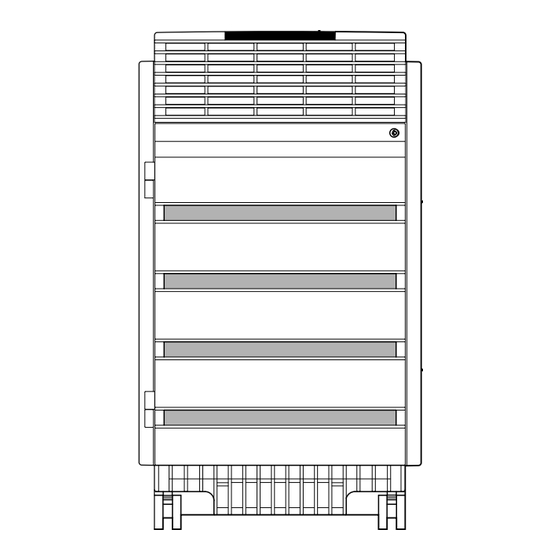
Page 25: Components: Front Of System
Components and Controls Figure 1–3 shows the components on the front of the system. Components: Front of System Figure 1–3 Front Components Air Plenum DC On/Off Switch Operator Control Panel Cable Guide Base Unit, Contains Fans 3 and 4 Fixed-Media Mass Storage Compartments Removable-Media Mass Storage Compartment MLO-007714 Getting Started 1–5... - Page 26 Components and Controls Figure 1–4 shows the operator control panel on the front of the Operator Control Panel system. Figure 1–4 Operator Control Panel DC On/Off Switch DC Power Light Self-Test Status Lights Reset Halt MLO-008872 For information about mass storage controls, refer to device- specific information in Chapter 5 of this guide.
-
Page 27: Components: Rear Of System
Components and Controls Figure 1–5 shows the major components at the rear of the Components: Rear of System system. Figure 1–5 Rear Components Serial and Model Number Label AC Circuit Breaker Cable Guide Base Unit, Contains Fans 1 and 2 Card Cage Power Subsystem MLO-007715... - Page 28 Components and Controls Figure 1–6 shows the module locations, lights, switches, and Card Cage connectors on the card cage at the rear of the system. Figure 1–6 Card Cage Futurebus+ Option Fault (Amber) Futurebus+ Option OK (Green) Console Terminal Port Console Terminal Ground Lug Auxilliary Serial Port ThinWire Fuse OK...
- Page 29 Components and Controls Power Figure 1–7 shows the lights, switches, and connectors on the Subsystem power supply at the rear of the system. Figure 1–7 Power Subsystem AC Circuit Breaker FEU Failure FEU OK DC3 Failure DC3 OK DC5 Failure DC5 OK Main Out Secondary In...
-
Page 30: System Operation: Overview
System Operation: Overview System Operation: Overview Two Levels of The system can run in one of two environments: Operation • Console mode • Operating system mode In console mode, the system and the console terminal operate Console Mode under the control of the console subsystem. All user input is passed to the console subsystem. -
Page 31: Starting The System
Starting the System Starting the System Before You You start a system by bringing it from a powered-down state Start the to the point at which the operating system login banner is System displayed on the console terminal. Before starting the system, you should be familiar with system components, lights, and controls. - Page 32 Starting the System • Local printer (optional) • Storage expander boxes (optional) • Standalone external devices (optional) Refer to the device’s installation instructions for information about powering up that device. Power Up the Power up your system as follows: System Step Action Find the AC circuit breaker at the rear of the system.
-
Page 33: System Power-Up Self-Test Screen
The screen shows the status and result of the self-tests. Figure 1–8 System Power-Up Self-Test Screen 17:33:56 Tuesday, January 26, 1993 Digital Equipment Corporation DEC 4000 AXP (tm) \ Executing Power-Up Diagnostics Memory Storage Net Futurebus+ 1 0 1 2 3... -
Page 34: Sample Power-Up Configuration Screen
Starting the System Figure 1–9 Sample Power-Up Configuration Screen CPU 0 DECchip 21064 PALcode Xn.nn, Firmware Tn.n-nnnn CPU 1 Memory 0 Memory 1 Memory 2 B2002-DA 128 MB Memory 3 Ethernet 0 Address 08-00-2B-2A-D6-97 Ethernet 1 Address 08-00-2B-2A-D6-A6 ID 0 ID 1 ID 2 ID 3... - Page 35 Starting the System For information about setting environment variables and the values to which environment variables have been preset, refer to What Variables Can I Set? in Chapter 4. Boot operating system software as follows: Boot Operating System Software Step Action Enter boot or b at the console prompt.
-
Page 36: Booting Openvms Axp System Software Screen
STDRV-I-STARTUP, VMS startup begun at 22-OCT-1992 15:21:00.13 %SET-I-NEWAUDSERV, identification of new audit server process is 00000027 %%%%%%%%%%% OPCOM 22-OCT-1992 15:21:21.83 %%%%%%%%%%% Example 1–2 shows a system booting DEC OSF/1 AXP software. Example 1–2 Booting DEC OSF/1 AXP System Software Screen (boot dka0.0.0.0.0 -flags 0) block 0 of dka0.0.0.0.0 is a valid boot block... -
Page 37: Using The Operator Control Panel
You shut down the system by performing the operating system software shutdown procedure. Refer to your operating system documentation. You can use the switches and buttons on the DEC 4000 AXP Overview control panel to do the following: •... -
Page 38: Invoke Console Mode
Using the Operator Control Panel Use Figure 1–10 to locate the controls that are identified in the procedures on the following pages. Figure 1–10 Operator Control Panel DC On/Off Switch DC Power Light Self-Test Status Lights Reset Halt MLO-008872 You may want to invoke console mode in order to set Invoke Console environment variables or to enter other console commands. - Page 39 Using the Operator Control Panel Invoke console mode as follows: Step Action Press the Halt button on the front of the system to the in position or do one of the following: • If the tta0_halts environment variable is set to 4 or 6, enter on the console terminal Break...
- Page 40 Using the Operator Control Panel Reset the Pressing the Reset button (shown in Figure 1–10) resets the System system. The system aborts all current processes, initializes, and performs startup self-tests. When the system is in console mode or in operating system mode, you use the Reset button, as a last resort, to reset the system if it hangs.
-
Page 41: Reset The System
Using the Operator Control Panel Power Down You use the DC on/off switch (shown in Figure 1–10) in the System conjunction with the AC circuit breaker to power down the system. Note You rarely need to power down the system. You may be able to accomplish your task by pressing the Reset button (See Reset the System, earlier in this chapter.) For maximum reliability, Digital recommends that you... -
Page 42: Help
In operating system mode: If you are running OpenVMS AXP, enter HELP at the DCL prompt If you are running DEC OSF/1 AXP, enter and the command for which you wish to receive information. • For information about other documentation that is available for your system, refer to the ‘‘information map’’... -
Page 43: References
References The following table describes where to find additional introductory information. Task Document Prepare the system site DEC 4000 Model 600 Series Site Preparation Checklist Install the system DEC 4000 Model 600 Series Quick Installation Install operating system Operating system software... -
Page 45: Console Subsystem
What Is the This chapter focuses on the console subsystem. The console Console subsystem provides the DEC 4000 AXP user interface when Subsystem? operating system software is not running or is halted. For example, you will use the console subsystem: •... -
Page 46: Components Of The Console Subsystem
Components of the Console Subsystem Components of the Console Subsystem Figure 2–1 identifies the components of the console subsystem. Console Subsystem • Console program — Software that executes when operating system software is not executing; provides the user interface, interprets and executes user commands. When the console program is executing, the system is running in console mode. - Page 47 Components of the Console Subsystem Figure 2–1 Console Subsystem d i i g t a l Data Test Talk Loop SD RD CD TR SI SCHOLAR Plus MLO-008871 Console Subsystem 2–3...
-
Page 48: Running The Console Program: Invoking Console Mode
Running the Console Program: Invoking Console Mode Running the Console Program: Invoking Console Mode You can invoke console mode on the system through the following Overview devices: • Console terminal • Remote access device: either a device connected to the auxiliary serial port on your system’s I/O module or a device that is on the same Ethernet segment as the system. -
Page 49: From The Auxiliary Serial Port
From Across Another way to access your system from a remote site is through the Ethernet the Ethernet. You can connect to your DEC 4000 AXP system from any device that is on the same Ethernet segment, or local area network. -
Page 50: Console Mode User Interface
Figure 2–2 shows the keyboard characters that are supported in Characters console mode. Some DEC 4000 AXP systems come with a VT420 terminal and keyboard. However, you can enter the following keyboard characters in console mode, regardless of your terminal type. -
Page 51: Supported Keys On A Vt420 Keyboard
Console Mode User Interface Callout Function < Deletes the last character you entered. < With a hardcopy terminal, is echoed with \ followed by the character being deleted. If you delete several characters consecutively, the system echoes with \ , the deleted characters, followed by another \ at the end of the series. -
Page 52: Control Characters
Console Mode User Interface Enter control characters by holding down the key labeled Ctrl Control Characters while pressing another key. You can enter the following control characters in console mode: Character Function Toggles between insertion and overstrike mode so Ctrl/A you can edit text on the current command line. -
Page 53: Console Commands
Console Commands What Are the Console Commands? In This Chapter The previous chapter describes the console subsystem. This chapter covers the console commands. Levels of There are two levels of console commands: Commands • Basic • Comprehensive Basic Most of the time, you will use the basic console commands. All of Commands the basic console commands are described in alphabetical order in this chapter. -
Page 54: Comprehensive Commands
Using these commands requires detailed Commands knowledge of your system. Do not use these commands without fully understanding the effect they can have on your DEC 4000 AXP system. To see a list of the comprehensive commands, enter help at the console prompt. -
Page 55: Entering Console Commands
The DEC 4000 AXP system features new console commands. New Console Commands Most of the DEC 4000 AXP console commands are similar, but not identical to, the console commands supported on VAX systems. (See Table 3–2.) If you are familiar with VAX console commands, familiarize yourself with the new commands before proceeding. - Page 56 Entering Console Commands How to Display commands instruct the system to display help show Output One information. When information fills more than one screen, the Page at a Time information scrolls until all information has been displayed. To make the system output easier to read, you can use the command to display the output one screen at a time.
-
Page 57: Synopsis
boot boot Bootstrap the system. Synopsis boot [-flags [longword,]longword] [-halt] [boot_device] Description Initializes the processor, loads a program image from the specified boot device, and transfers control to that image. If you specify a list of devices, a bootstrap is attempted from each device in order. -
Page 58: Flags
Ethernet port, eza0. Boot flag settings are 0 and 1. >>> boot -flags 0,1 dka0,eza0 In the next example, an DEC OSF/1 AXP system boots from the SCSI disk, dka0, using boot flag setting i. >>> boot -flags i dka0 In the next example, the system boots from the SCSI disk, dka0, but remains in console mode. -
Page 59: Cdp
Configure DSSI parameters. Synopsis cdp [-{a,i,n,o,u}] [-sn] [-sa allclass] [-su unitnum] [dssi_device] Description command allows you to modify DSSI device parameters from the console terminal without connecting to a node’s DUP server. The parameters that are modified are the DUP task parameters: NODENAME, ALLCLASS, and UNITNUM. - Page 60 Flag Description Sets the node name (NODENAME) for all DSSI devices in the system to either RFhscn or TFhscn, where h is the device hose number (0), s is the device slot number (0), c is the device channel number (0..3), and n is the device node ID number (0..6).
- Page 61 In the next example, the system sets the starting unit number for the first dua device in the system to the number 10. In increasing increments of 1, each subsequent dua device is also assigned a new unit number. >>> cdp dua* -su 10 pua0.0.0.0.0 ALPHA0 0411214901371...
-
Page 62: Examples
continue continue Resume program execution on the specified processor. Synopsis continue Description Continues execution on the specified processor, or the primary processor if a processor is not specified. The processor begins executing instructions at the address that is currently in the program counter. -
Page 63: Date
date date Display or modify the current date and time. Synopsis date [yyyymmddhhmm.ss] Description Displays or modifies the current time and date. If you do not specify any arguments, the current date and time are displayed. If you specify arguments, modifies the arguments that you date specify in the time-of-year (TOY) clock. -
Page 64: Examples
date Examples In the following example, the system is commanded to display the current date and time. >>> date 23:29:10 Monday, May 11, 1992 In the next example, the year, month, date, hour, and minute are set on the system. >>>... -
Page 65: Help Or Man
• If you enter the help argument after the command, the help command displays general information about the DEC help 4000 AXP system’s console commands and online help. Parameters Parameter Description command . . . -
Page 66: Init
init init Initialize the system. Synopsis init Description Initializes the system. The system performs a software reset and executes the power-up self-tests. Entering the command is nearly equivalent to pressing init the Reset button. The difference is that part of memory is not retested when you enter the command. -
Page 67: Man
help Console Commands 3–15... -
Page 68: Set
Set or modify the value of an environment variable. Synopsis set [-default] envar val Description Sets or modifies the value of an environment variable. Environment variables are used to pass configuration information between the console and the operating system. Parameters Parameter Description envar... - Page 69 Sets additional parameters to be passed to system software. When using OpenVMS AXP software, these parameters are the system root number and boot flags. When using DEC OSF/1 AXP software, this parameter is boot flag. The default setting is null. language Sets the language in which system software and layered products will be displayed.
-
Page 70: Examples
Variable Description tta0_halts Sets the ability to halt the system from the console terminal keyboard by pressing Ctrl/P . Possible settings are 0: Ctrl/P and Break are disabled; 2: Ctrl/P is enabled; 4: Break is enabled; 6 Ctrl/P and Break Break enabled. -
Page 71: Set Host
set host set host Connect the console program to the MSCP DUP server on a Synopsis DSSI device. set host -dup [-task task_name] device Description Connects the console program to another DUP server on a DSSI device. In the syntax, device is the name of the device to attach to the console program. - Page 72 set host Examples The following example shows how to connect to the MSCP DUP server on a device. >>> show device du dud0.0.0.3.0 R2YQYA$DIA0 RF72 >>> set host -dup dud0 starting DIRECT on pud0.0.0.3.0 (R2YQYA) Copyright (C) 1990 Digital Equipment Corporation PRFMON V1.0 D 2-NOV-1990 10:30:58 DKCOPY V1.0 D 2-NOV-1990 10:30:58 DRVEXR V2.0 D 2-NOV-1990 10:30:58...
-
Page 73: Show
show show Display an environment variable value or other information. Synopsis show [envar] [{config,device,memory,pal,version}] Description Displays the current value (or setting) for an environment variable that you specify. Alternatively, displays other information about the system, according to the parameters that you enter on the command line. - Page 74 show Environment Variable Description Variables auto_action Displays the console action following an error, halt, or power-up: either halt, boot, or restart. bootdef_dev Displays the device or device list from which bootstrapping is attempted. boot_osflags Displays the additional parameters to be passed to system software.
- Page 75 show Examples In the following example, the system displays the version of the console program that is installed on the system. The console program version is V3.0-1. >>> show version version V3.0-1 Sep 20 1992 00:28:54 >>> In the next example, the default system power-up action is displayed.
- Page 76 test test Tests the system. Synopsis test Description Performs a test on the entire system, excepting tape drives. When the tests are successfully completed, the message ‘‘tests done’’ is displayed. If any of the tests fail, a failure message is displayed.
-
Page 77: Reference
Error in read of 0 bytes at location 0005D200 from device dkd200.2.0.3.0 *** End of Error *** tests done >>> References The following table describes where to find additional information about the console commands. Task Document Enter comprehensive console DEC 4000 AXP Model 600 Series commands Technical Manual Console Commands 3–25... -
Page 79: Chapter Description
Variable? An environment variable is a firmware parameter that you can access from console mode. The DEC 4000 AXP console program includes multiple environment variables. The setting of these firmware parameters affects the way the system powers up and boots operating system software. -
Page 80: Overview: Do I Need To Set Environment Variables
Overview: Do I Need to Set Environment Variables? Overview: Do I Need to Set Environment Variables? Although it is not essential to set environment variables, setting Deciding to Set Environment environment variables can simplify the operation of your system. Variables You set environment variables from console mode. - Page 81 Overview: Do I Need to Set Environment Variables? Table 4–1 Environment Variables Variable Function Factory Setting auto_action Specifies what action the console should Halt take any time the system is powered up, crashes, or the Reset button is pressed. bootdef_dev Specifies the default boot device to the System device on which system.
-
Page 82: Before You Begin
Before You Begin Before You Begin Preliminary Before changing any environment variables, you should have Actions done the following: • Placed your system at the console prompt. If your system is not displaying the >>> prompt, refer to Invoke Console Mode in Chapter 1. •... -
Page 83: Your System's Current Startup Action
Changing the Default Startup Action (auto_action) To display your system’s current default startup action, enter the Your System’s Current Startup following: Action >>> show auto_action Return The system responds with a display similar to the following: auto_action boot In this example, the default startup action is boot. Setting the default startup action to halt will cause your system Choosing ‘‘Halt’’... -
Page 84: Set The Default Startup Action
Changing the Default Startup Action (auto_action) To set the default startup action, complete the following steps: Set the Default Startup Action Step Action Are you choosing the boot or the restart startup action? • No. Proceed to the next step. •... -
Page 85: Setting Or Changing The Default Boot Device (Bootdef_Dev)
Setting or Changing the Default Boot Device (bootdef_dev) Setting or Changing the Default Boot Device (bootdef_dev) Default Boot The boot device is the device from which the bootstrap system Device software is acquired. In most cases, the default boot device has been identified on your system as the device on which Factory Installed Software (FIS) was loaded. -
Page 86: Preliminary Considerations
Setting or Changing the Default Boot Device (bootdef_dev) For instance, to try booting software from SCSI devices: >>> boot dka0 boot dka0.1.0.2.0 -flags 0 block 0 of dka0.1.0.2.0 is not a valid boot block bootstrap failure >>> >>>boot dka1 boot dka1.1.0.2.0 -flags 0 booting system software... - Page 87 Setting or Changing the Default Boot Device (bootdef_dev) Set or change the default boot device as follows: Set or Change the Default Boot Device Step Action Determine the device or devices that you wish to set as the default. If a default boot device has not been set and you do not know your system’s boot device, see the previous section Which One Is the Boot Device? Set the environment variable by entering the...
-
Page 88: Setting Boot Flags (Boot_Osflags)
Setting Boot Flags (boot_osflags) Setting Boot Flags (boot_osflags) What Are Boot Boot flags contain information that is read and used by the Flags? operating system during a system bootstrap procedure. Boot flags may be passed to the operating system either on the command line with the -flags option (see boot in Chapter 3) boot or by setting the boot_osflags environment variable as described... - Page 89 Setting Boot Flags (boot_osflags) Boot Flag Settings Possible boot flags settings and their meanings for OpenVMS AXP systems are: Flag Setting Bit Number Meaning Bootstrap conversationally (enables you to modify SYSGEN parameters in SYSBOOT). Map XDELTA to running system. Stop at initial system breakpoint. Perform diagnostic bootstrap.
-
Page 90: Your System's Current Default Boot Flags
Setting Boot Flags (boot_osflags) Boot Flags The DEC OSF/1 AXP operating system takes only one boot flag Settings for argument: the boot flag. DEC OSF/1 Possible boot flag settings and their meanings for DEC OSF/1 AXP Systems AXP systems are:... -
Page 91: Set Boot Flags
>>> set boot_osflags 1 In DEC OSF/1 AXP, to set the boot flags to autoboot, enter the following: >>> set boot_osflags a Set another environment variable or reboot the system. -
Page 92: Setting The Language (Language)
Setting the Language (language) Setting the Language (language) Do I Need The DEC 4000 AXP system ships from the factory with a default to Set the language setting that determines the language that the system Language? will display on the console terminal. -
Page 93: Changing The Baud Rate (Tta0_Baud And Tta1_Baud)
Setting the Language (language) To set the language that the system displays on output devices, Change the Language do the following: Step Action Determine the code number for the language you want system output devices to display. Enter the following: >>>... -
Page 94: Displaying The Current Baud Rates
Changing the Baud Rate (tta0_baud and tta1_baud) Displaying the The default setting for both tta0_baud and tta1_baud is 9600. Current Baud Displaying the Console Terminal Port Baud Rate Rates To display your console terminal port’s baud rate, enter the following: >>>... - Page 95 Changing the Baud Rate (tta0_baud and tta1_baud) Change a baud rate as follows: Change the Baud Rate Step Action Determine the baud rate to which you must set the console terminal or auxiliary serial port. The possible settings are: 1200 2400 4800 9600...
-
Page 96: Why Enable Halt Key Functions
Enabling Halt Key Functions (tta0_halts and tta1_halts) Enabling Halt Key Functions (tta0_halts and tta1_halts) Why Enable To invoke console mode (halt the system), you must press the Halt Key Halt button on the system. Alternatively, you can invoke console Functions? mode from a terminal keyboard. -
Page 97: When You Have Finished Setting Variables
Enabling Halt Key Functions (tta0_halts and tta1_halts) Displaying Your Auxiliary Serial Device’s Halt Key Settings To display current halt key settings for the device connected to the auxiliary serial port, enter the following: >>> show tta1_halts Return tta1_halts In this example, tta1_halts is set to 0: Ctrl/P and Break disabled. -
Page 99: Operating Mass Storage Devices
Operating Mass Storage Devices Chapter Description Overview Mass storage devices are drives that are used to store large amounts of data for extended periods. The DEC 4000 AXP system uses both DSSI and SCSI mass storage devices to store data. In This Chapter This chapter covers the following information: •... -
Page 100: Dec 4000 Axp Mass Storage Devices And Compartments
DEC 4000 AXP Mass Storage Devices and Compartments DEC 4000 AXP Mass Storage Devices and Compartments Identifying Mass storage devices are located in five compartments inside Mass Storage your system as shown in Figure 5–1. Four compartments are Compartments reserved for fixed-media drives ( – ); these drives include RZ-series and RF-series drives. -
Page 101: Storage Compartments
Operating DEC 4000 AXP Mass Storage Devices Figure 5–1 Storage Compartments Fixed-Media Mass Storage Compartments Removable-Media Mass Storage Compartment MLO-009360 Operating Mass Storage Devices 5–3... -
Page 102: Operating Dec 4000 Axp Devices
The remaining sections of this chapter describe how to operate Operating DEC 4000 AXP each DEC 4000 AXP mass storage device. Table 5–1 describes the devices that are available for use with the DEC 4000 AXP Devices system: Table 5–1 Devices Supported by the DEC 4000 AXP... -
Page 103: Operating Rz- And Rf-Series Disk Drives
Operating RZ- and RF-Series Disk Drives Operating RZ- and RF-Series Disk Drives RZ- and RZ- and RF-series drives are fixed-media disk drives that store RF-Series up to 2 gigabytes of information on a disk that remains fixed Description inside the drive. RZ-series drives are SCSI compatible; RF-series drives are DSSI compatible. -
Page 104: Front Panels For Rz-Series (Scsi) Disk Drives
Operating RZ- and RF-Series Disk Drives Figure 5–2 Front Panels for RZ-Series (SCSI) Disk Drives Fast SCSI 3.5-Inch SCSI 5.25-Inch SCSI MLO-009368 Fault light (amber) Local disk converter OK light Online light SCSI terminator 5–6 Operating Mass Storage Devices... -
Page 105: Rz- And Rf-Series Fault Light
Operating RZ- and RF-Series Disk Drives Figure 5–3 Front Panels for RF-Series (DSSI) Disk Drives 3.5-Inch DSSI 5.25-Inch DSSI MLO-009369 Fault light (amber) Local disk converter OK light Online light DSSI terminator Write-Protect button Run/Ready button RZ- and Each RZ- and RF-series disk drive has a fault light located on RF-Series Fault the front panel (see Figure 5–2 and Figure 5–3). -
Page 106: Write-Protecting An Rz- Or Rf-Series Disk
Operating RZ- and RF-Series Disk Drives Write-Protecting The RZ- and some RF-series drives, have no Write-Protect an RZ- or button. You set write-protection through console commands in RF-Series Disk console mode. Software Write-Protect for RZ- and RF-Series Drives To software write-protect an RZ- or RF-series drive on the OpenVMS AXP operating system, enter the following DCL command: $ MOUNT device_name volume_label /SYSTEM/NOWRITE... - Page 107 Operating RZ- and RF-Series Disk Drives Console Mode Write-Protect For RF-Series Drives The console mode write-protect provides a more permanent write-protection than the software write-protect. Once you write-protect an RF-series drive from console mode, it remains write-protected, regardless of the availability of the operating system or if the system is powered down.
- Page 108 Operating RZ- and RF-Series Disk Drives b. Access the DUP driver by setting host to the specific device you want to write protect. Use the following command: >>> set host -dup device_name -task params The device_name is the complete device name (console device name or OpenVMS AXP device name) as shown using the show device du...
- Page 109 Operating RZ- and RF-Series Disk Drives Example 5–1 Setting Hardware Write-Protection Through Firmware >>> set host -dup dua0.0.0.0.0 -task params Starting DUP server... Copyright (c) 1992 Digital Equipment Corporation PARAMS> SET WRT_PROT 1 PARAMS> WRITE PARAMS> SHOW WRT_PROT Parameter Current Default Type Radix...
-
Page 110: Operating The Rrd42 Compact Disc Drive
Operating the RRD42 Compact Disc Drive Operating the RRD42 Compact Disc Drive RRD42 The RRD42 compact disc drive reads information from Description removable, read-only compact discs that hold up to 600 megabytes per compact disc. Figure 5–4 shows the components of the RRD42. -
Page 111: Rrd42 Compact Disc Drive And Compact Disc
Operating the RRD42 Compact Disc Drive Figure 5–4 RRD42 Compact Disc Drive and Compact Disc MLO-008851 Operating Mass Storage Devices 5–13... -
Page 112: Inserting A Compact Disc
Operating the RRD42 Compact Disc Drive Inserting a To insert a compact disc into the RRD42 (Figure 5–5): Compact Disc 1. Gather both the compact disc caddy and the disc you wish to insert. 2. If there is a protective film on the center of the caddy lid, remove the film 3. -
Page 113: Inserting And Removing A Compact Disc
Operating the RRD42 Compact Disc Drive Figure 5–5 Inserting and Removing a Compact Disc MLO-008864 Operating Mass Storage Devices 5–15... -
Page 114: Operating The Tlz06 Tape Drive
Operating the TLZ06 Tape Drive Operating the TLZ06 Tape Drive TLZ06 The TLZ06 tape drive stores information on removable tape Description cartridges that can hold up to 4 gigabytes per tape cartridge. Figure 5–6 shows the components of the TLZ06. Tape unload button Tape cassette slot Write-protect light... -
Page 115: Tlz06 Drive And Compatible Tape
Operating the TLZ06 Tape Drive Figure 5–6 TLZ06 Drive and Compatible Tape MLO-008194 Operating Mass Storage Devices 5–17... -
Page 116: Inserting A Tape Into The Tlz06
Operating the TLZ06 Tape Drive Inserting a Tape To insert the DDS tape into the TLZ06 (Figure 5–7): into the TLZ06 1. Check to see that the tape/activity light on the drive is unlit. If it is lit, there is already a tape in the drive. Remove the tape from the drive before continuing. -
Page 117: Inserting And Removing A Tape: Tlz06
Operating the TLZ06 Tape Drive Figure 5–7 Inserting and Removing a Tape: TLZ06 MLO-008865 Operating Mass Storage Devices 5–19... -
Page 118: Tlz06 Lights
Operating the TLZ06 Tape Drive TLZ06 Lights Table 5–2 summarizes the conditions indicated by the TLZ06 lights. Table 5–2 TLZ06 Light Summary Write-Protect Light Tape/Activity Light Condition No tape loaded Green Tape loaded and write-enabled Blinking green Busy Amber Green Tape loaded and write-protected. - Page 119 Operating the TLZ06 Tape Drive Table 5–2 (Cont.) TLZ06 Light Summary Write-Protect Light Tape/Activity Light Condition Blinking Blinking green. Test Drive fault. amber failure. Operating Mass Storage Devices 5–21...
-
Page 120: Operating The Tz85 Tape Drive
Operating the TZ85 Tape Drive Operating the TZ85 Tape Drive TZ85 The TZ85 tape drive stores information on removable cassette Description tapes that can hold up to 2.6 gigabytes each. Figure 5–8 shows the components of the TZ85. Unload button Operate Handle light Use Cleaning Tape light Tape in Use light... -
Page 121: Tz85 Drive And Compatible Tape
Operating the TZ85 Tape Drive Figure 5–8 TZ85 Drive and Compatible Tape MLO-008850 Operating Mass Storage Devices 5–23... -
Page 122: Inserting A Tape Into The Tz85
Operating the TZ85 Tape Drive Inserting a Tape To insert the TZ85 tape cartridge into the drive (Figure 5–9): into the TZ85 1. If the Operate Handle light is on solid green, proceed to the next step. If the Operate Handle light is not on, there is probably a tape in the drive. -
Page 123: Inserting A Tape Into The Tz85
Operating the TZ85 Tape Drive Figure 5–9 Inserting a Tape into the TZ85 MLO-008839 Operating Mass Storage Devices 5–25... -
Page 124: Removing A Tape From The Tz85
Operating the TZ85 Tape Drive Removing a To remove a tape cartridge from the TZ85 (Figure 5–10): Tape from the 1. Press the Unload button on the front of the drive TZ85 Wait for the Tape in Use light to go off and the Operate Handle light to come on. -
Page 125: Removing A Tape From The Tz85
Operating the TZ85 Tape Drive Figure 5–10 Removing a Tape from the TZ85 MLO-008840 Operating Mass Storage Devices 5–27... -
Page 126: Tz85 Lights
Operating the TZ85 Tape Drive TZ85 Lights Table 5–3 summarizes the conditions indicated by the TZ85 lights. Table 5–3 TZ85 Light Summary Light State Condition Green Okay to operate the cartridge insert/release handle. Not okay to operate the cartridge insert/release handle. Yellow Blinking regularly Tape is loading or... -
Page 127: Operating The Tz30 Tape Drive
Operating the TZ30 Tape Drive Operating the TZ30 Tape Drive TZ30 The TZ30 cartridge tape drive stores information on removable Description tape cartridges that can hold up to 95 megabytes per tape cartridge. Figure 5–11 shows the components of the TZ30. Up to four TZ30 drives can be located in the removable-media mass storage compartment. -
Page 128: Tz30 Tape Drive And Compatible Tape
Operating the TZ30 Tape Drive Figure 5–11 TZ30 Tape Drive and Compatible Tape MLO-007725 5–30 Operating Mass Storage Devices... - Page 129 Operating the TZ30 Tape Drive Write Protect light (orange) Tape in Use light (yellow) Operate Lever light (green) Unload button Drive lever CompacTape slot CompacTape cartridge Caution Do not push a tape cartridge into the TZ30 while moving the cartridge lever between the lock and unlock positions. Doing so can damage the drive.
-
Page 130: Inserting A Tape Into The Tz30
Operating the TZ30 Tape Drive Inserting a Tape To insert the TZ30 tape into the drive (Figure 5–12): into the TZ30 1. If the cartridge lever on the drive is in the lock position, move the lever to the unlock position 2. -
Page 131: Inserting A Tape Into The Tz30
Operating the TZ30 Tape Drive Figure 5–12 Inserting a Tape into the TZ30 108% MLO-008837 Operating Mass Storage Devices 5–33... -
Page 132: Remove Tapes Before Power-Down
Operating the TZ30 Tape Drive Remove Caution Tapes Before Remove tape cartridges from the TZ30 before turning off Power-Down power to the drive or the system. Failure to do so can damage the cartridge and tape drive. Removing a To remove a tape from the TZ30 drive (Figure 5–13): Tape from the 1. -
Page 133: Removing A Tape From The Tz30
Operating the TZ30 Tape Drive Figure 5–13 Removing a Tape from the TZ30 108% 108% 108% MLO-008838 Operating Mass Storage Devices 5–35... -
Page 134: Tz30 Lights
Operating the TZ30 Tape Drive TZ30 Lights Table 5–4 summarizes the conditions indicated by the TZ30 lights. Table 5–4 TZ30 Light Summary Light State Condition Green Okay to operate the cartridge lever. Do not operate the cartridge lever. Blinking The drive detected a cartridge or calibration error. -
Page 135: Maintaining Mass Storage Media And Devices
Maintaining Mass Storage Media and Devices Maintaining Mass Storage Media and Devices Several tasks go hand-in-hand with using mass storage devices: Task Overview • Write-enabling and write-protecting media • Labeling removable media • Handling the media according to its care instructions •... -
Page 136: Labeling Removable Media
Maintaining Mass Storage Media and Devices Labeling Once you copy information onto removable media, label the Removable contents of the media with the labels provided in the media’s Media packaging. Each type of tape has a label position, usually indicated by an indentation in the media. -
Page 137: Caddy Shutter
Maintaining Mass Storage Media and Devices • Do not touch the surface of a disc. Handle a disc by its edges. • Wipe a disc with a compact disc cleaner when dust or fingerprints contaminate its surface. • Never manually open the caddy shutter, shown in Figure 5–15, or touch the disc. -
Page 138: Cleaning The Tlz06
Maintaining Mass Storage Media and Devices • Keep tapes away from anything that contains a magnet or a magnetic field, such as a telephone or a computer monitor. Any tape exposed to a magnetic field can lose information. • Store tapes in a dust-free area where the relative humidity is between 20% and 80%. -
Page 139: Cleaning The Tz30
Maintaining Mass Storage Media and Devices Under normal conditions, the head cleaning cassette is good for approximately 25 cleanings. Additional cassettes are available from your Digital sales representative or DECdirect (800-DIGITAL). If the head cleaning cassette has been used more than 25 times, both the tape/activity and write-protect lights will flash. -
Page 140: References
References References The following table describes where to find additional information about DEC 4000 AXP mass storage devices. Task Document Obtain a list of all DEC 4000 Systems and Options Catalog AXP–compatible devices Write data to or from a drive •... -
Page 141: System Configuration
System Configuration Chapter Description Introduction This chapter describes your system configuration and explains how to plan changes in the configuration. Your system configuration is defined by the modules and mass storage devices inside your system, as well as the external options to which your system is connected. -
Page 142: Identifying Your Configuration
When assigning an identification number to a device • When ordering additional equipment • When connecting to a network Types of Figure 6–1 illustrates the most common DEC 4000 AXP Configurations configurations: • Standalone system with or without external mass storage A standalone system is not connected to any other systems or to a network. -
Page 143: Types Of Configurations
Identifying Your Configuration Figure 6–1 Types of Configurations Ethernet MLO-009227 System Configuration 6–3... -
Page 144: Special Configurations
Dual CPU systems • DSSI VMScluster Dual CPU A second CPU can be added to any DEC 4000 AXP system. Systems Adding a second CPU approximately doubles the computing power of the original system. A DSSI VMScluster configuration consists of two or more... -
Page 145: Benefits Of A Dssi Vmscluster
Special Configurations Benefits The benefits of a DSSI VMScluster configuration are: of a DSSI • Cluster features such as shared data across systems and VMScluster satellite nodes. • High system availability. If one of the systems is unavailable, for example, due to a system malfunction, the satellites booted through it are able to continue operating through the other system. -
Page 146: Identifying System Options
Identifying System Options Identifying System Options In addition to your configuration type, your system configuration Specifics of Your includes the following: Configuration • System modules • Mass storage devices • External mass storage devices that are connected to the system (optional) •... -
Page 147: External Mass Storage Devices
Identifying System Options External Your system can support devices that are outside the system Mass Storage unit (external devices) in addition to the devices that are in Devices the system. External devices can sit or stand alone beside your system, or they can be housed in a separate enclosure, such as the R400X mass storage expander. -
Page 148: Buses Associated With Each Compartment
Identifying Mass Storage Devices Table 6–1 Mass Storage Compartments and Devices DSSI Compartments SCSI Compartments Contain DSSI bus Contain SCSI bus Hold only DSSI devices Hold only SCSI devices Are fixed-media and contain If fixed-media, contain RZ- RF-series drives series drives No support for removable-media If removable-media, contain some combination of RRD42,... -
Page 149: Drive Addresses
Identifying Mass Storage Devices Determine a drive address by identifying the bus on which the drive is located and the drive ID. The letter of the drive is etched on the machine. For example, the address of the drive in Figure 6–2 ( ) is Bus E, Drive ID 1. -
Page 150: Displaying Configuration Information Online
Displaying Configuration Information Online Displaying Configuration Information Online You can examine information about your system configuration on Overview line from console mode by entering a command at your console terminal. The system responds by displaying information about the topic that you specify. You can display information about the following topics: •... -
Page 151: System Configuration Display
Displaying Configuration Information Online Example 6–1 System Configuration Display >>> show config Return Console T2.4-2859 VMS PALcode X5.12F, OSF PALcode X1.09B CPU 0 B2001-AA DECchip (tm) 21064-2 CPU 1 Memory 0 B2002-DA 128 MB Memory 1 Memory 2 Memory 3 Ethernet 0 08-00-2B-1D-02-8F Ethernet 1... -
Page 152: Displaying Memory Information
Displaying Configuration Information Online Displaying To display memory information from console mode, enter show Memory memory at the console prompt. Information >>> show memory Your system memory is displayed on the terminal screen. Example 6–2 shows a possible memory configuration display. Example 6–2 Memory Configuration Display >>>... -
Page 153: Device Configuration Display
Displaying Configuration Information Online Displaying To display device information from console mode, enter show Device device at the console prompt. Information >>> show device Your device configuration is displayed on the terminal screen. Example 6–3 shows a possible device configuration display. Example 6–3 Device Configuration Display >>>... -
Page 154: Device Name Convention
Displaying Configuration Information Online The device naming convention is shown in Figure 6–3. Figure 6–3 Device Name Convention dka0.0.0.0.0 Bus Number: 0 LBus; 1 Futurebus+ Slot Number: 0-4 SCSI/DSSI; 6, 7 Ethernet; 2-13 Futurebus+ nodes Channel Number: Used for multi-channel devices. Bus Node Number: Bus Node ID (from bus node ID plug) Device Unit Number:... -
Page 155: Displaying Console Program Version
Displaying Configuration Information Online Displaying To display the version of the console program that you are using, Console enter show version at the console prompt. Program >>> show version Version The version of the console program that your system is using is displayed on the terminal screen. -
Page 156: Planning A Change To Your Configuration
2. Obtain a copy of the Systems and Options Catalog from your Digital sales representative and fill out the DEC 4000 AXP configuration worksheet that can be found in the catalog. 3. Order the options and arrange for Digital Services to install them. -
Page 157: Perform Post-Upgrade Tasks
Planning a Change to Your Configuration Perform After Digital Services installs the options, you may want to do Post-Upgrade one or more of the following tasks: Tasks • Set parameters for DSSI devices For information about how to do this, refer to Setting and Examining Parameters for DSSI Devices, later in this chapter. -
Page 158: Connecting Additional Devices To Your System
SCSI, you must reconfigure the hardware in that compartment. Contact your Digital service representative. Connecting Each DEC 4000 AXP mass storage compartment can hold up to four devices. However, each bus can support up to seven Additional mass storage devices. This means that you can connect three,... -
Page 159: Mass Storage Bus Expansion Ports
Connecting Additional Devices to Your System Figure 6–4 Mass Storage Bus Expansion Ports Fixed-Media Mass Storage Compartment MLO-009359 • Bus A expansion port • Bus B expansion port • Bus C expansion port • Bus D expansion port • Bus E expansion port System Configuration 6–19... -
Page 160: Terminating And Extending A Bus
Connecting Additional Devices to Your System Terminating To extend a bus, you attach a bus expansion cable (either DSSI and Extending or SCSI, to match the bus) to the bus expansion port and attach a Bus the other end of the cable into the external device. To terminate a bus, you attach a terminator (either DSSI or SCSI, to match the bus) to the bus expansion port. -
Page 161: Terminating And Extending A Bus
Connecting Additional Devices to Your System Figure 6–5 Terminating and Extending a Bus MLO-008869 System Configuration 6–21... -
Page 162: Changing Drive Id Numbers
Changing Drive ID Numbers Changing Drive ID Numbers When to Each drive ID number is determined at the factory. Extra drive Change Drive ID plugs are supplied with your system. You may need to use ID Numbers the extra plugs to renumber your drives under the following circumstances: •... -
Page 163: Changing A Drive Id Plug
Changing Drive ID Numbers The drive ID plugs have prongs on the back that indicate the bus Changing a Drive ID Plug node number (and by default, the unit number) of the drive. Change a drive ID plug as shown in Figure 6–6. •... -
Page 164: Setting And Examining Parameters For Dssi Devices
Setting and Examining Parameters for DSSI Devices Setting and Examining Parameters for DSSI Devices When to You may need to change DSSI device parameters under the Change following circumstances: DSSI Device • If you reconfigure your system to include DSSI devices in an Parameters expander •... - Page 165 Setting and Examining Parameters for DSSI Devices show device du command displays information for all show device du pu DSSI devices in the system. The argument lists all DSSI drives; the argument lists the storage adapters for all DSSI buses found on the system. Synopsis: show device du pu Example:...
-
Page 166: Cdp
Setting and Examining Parameters for DSSI Devices ALLCLASS is the allocation class for the system and devices, and u is a unique unit number. For example, $1$DIA0. Node name (alphanumeric, up to 6 characters) Device type command allows you to modify NODENAME, ALLCLASS, and UNITNUM from the console program without explicit connection to a node’s DUP server. -
Page 167: Dssi Device Parameter Descriptions
Setting and Examining Parameters for DSSI Devices DSSI Device Drive ID Parameter The drive ID parameter is provided by the drive ID plug on the Descriptions front panel of the storage compartment. Each DSSI bus can support up to eight devices, (drive IDs 0–7). Each DSSI adapter and each device count as a node. -
Page 168: How Openvms Axp Uses The Dssi Device Parameters
ALLCLASS is the allocation class for the system and devices, and u is a unique unit number. With DEC 4000 AXP systems, you can fill multiple DSSI buses: buses A–D (slot numbers 0–3). Each bus can have up to seven DSSI devices (drive IDs 0–6). -
Page 169: Example: Modifying Dssi Device Parameters
Following Figure 6–8 is an example in which the allocation class Parameters will be set to 1, the devices for Bus A (in the DEC 4000 AXP) will be assigned new unit numbers (to avoid the problem of duplicate unit numbers), and the system disk will be assigned a new node name. -
Page 170: Sample Dssi Buses For An Expanded Dec 4000 Axp System
Setting and Examining Parameters for DSSI Devices Figure 6–8 Sample DSSI Buses for an Expanded DEC 4000 AXP System System 3 2 1 0 Expander DSSI Cable Bus A Bus B DSSI Terminator Locations LJ-02065-TI0 6–30 System Configuration... - Page 171 Setting and Examining Parameters for DSSI Devices In this part of the example, the system displays all DSSI devices. show device du pu >>> dua0.0.0.0.0 $2$DIA0 (ALPHA0) RF35 dua1.1.0.0.0 $2$DIA1 (ALPHA1) RF35 dua2.2.0.0.0 $2$DIA2 (ALPHA2) RF35 dua3.3.0.0.0 $2$DIA3 (ALPHA3) RF35 dub0.0.0.1.0 $2$DIA0 (SNEEZY) RF73...
-
Page 172: Using The Power Control Bus With A Storage Expander
Using the Power Control Bus with a Storage Expander The three power bus connectors on the power system controller Power Control at the rear of the DEC 4000 AXP system allow you to configure Bus for Expanded a power bus for systems expanded with the R400X expander. -
Page 173: References
Using the Power Control Bus with a Storage Expander Figure 6–9 Sample Power Bus Configuration System Expander 1 Expander 2 MLO-009370 References The following table describes where to find additional configuration information. Task Document Review available options Systems and Options Catalog Connect your system to the Network Installation Guide network... -
Page 175: Learning More About Your System
Learning More About Your System Chapter Description Introduction This chapter describes your system’s design and the design of its subsystems and components. This chapter covers the following information: In This Chapter • System Features • Subsystems and Components • CPU Subsystem •... -
Page 176: System Features
VAX investment protection • DSSI VMScluster support Alpha AXP The DEC 4000 AXP system is part of a family of flagship Architecture computers that are based on the new Alpha AXP system architecture. Alpha AXP architecture employs the DECchip 21064 microprocessor, which is located on the CPU module of each Alpha AXP system. -
Page 177: Integration With Existing Technology
• DEC OSF/1 AXP The NT AXP operating system and other operating systems are planned to be supported in the future. Integration The DEC 4000 AXP system is designed to be compatible with with Existing existing technology: Technology • VAX hardware DEC 4000 AXP, like all Alpha AXP systems, can connect to your existing VAX hardware in clusters and networks. -
Page 178: Subsystems And Components
Subsystems and Components Subsystems and Components The subsystems that make up the DEC 4000 AXP system are Overview described in Table 7–1 and shown in Figure 7–1. Table 7–1 DEC 4000 AXP Subsystems Subsystem Features System bus Supports: • Up to two CPU modules •... -
Page 179: Dec 4000 Axp System Architecture
Subsystems and Components Figure 7–1 DEC 4000 AXP System Architecture Power Subsystem To Outlet Front Power System Unit Contr Serial Control Bus Memory 3 Memory 2 CPU 1 Memory 1 CPU 0 Memory 0 Operator Control 64, 128 MB Panel... -
Page 180: Cpu Subsystem
CPU Subsystem CPU Subsystem The CPU subsystem consists of the following components: Components • System bus • Central processing units (1 or 2) • Memory modules (1 to 4) • I/O module The system bus interconnects the CPUs, memory modules, System Bus and I/O module. -
Page 181: I/O Module
CPU Subsystem Memory Module Main memory provides the electrical storage area for data and instructions used by the CPU. DEC 4000 AXP systems support from one to four memory modules. Each memory module features the following: • Error detection and correction (EDC) logic •... -
Page 182: Serial Control Bus
CPU Subsystem • One asynchronous serial line unit (SLU) dedicated to the console subsystem. • One additional asynchronous SLU with modem control. • Serial control bus controller for communications with other components of the system. The serial control bus is a two-conductor serial interconnect bus Serial Control that is independent of the system bus. -
Page 183: Power Subsystem
Power Supply your system. Connecting an uninterruptible power supply (UPS) (Optional) to the DEC 4000 AXP system can keep the system running for approximately 30 minutes after a power failure. For information about ordering a UPS for your system, refer to the Systems and Options Catalog. -
Page 184: Storage Subsystem
fixed-media devices, such as fixed-disk drives and removable-media devices, such as tape cartridges and compact discs. Mass Storage You can expand mass storage capacity on a DEC 4000 AXP system by connecting it to a mass storage expander, such as the Expansion R400X or SF100. -
Page 185: Futurebus+ Subsystem
Futurebus+ Subsystem Futurebus+ Subsystem DEC 4000 AXP systems implement Futurebus+ Profile B as the Overview I/O bus. Features of Futurebus+ include: • Industry open standard bus • 32- or 64-bit, multiplexed address and data bus • Asynchronous protocol • Centralized arbitration •... -
Page 187: Care, Maintenance, And Exterior Customizations
Care, Maintenance, and Exterior Customizations Chapter Description Introduction This chapter focuses on the care and maintenance of your system as well as the customizations that you can make to the system’s exterior. This chapter covers the following information: In This Chapter •... -
Page 188: Locate Accessories
Customizing the System Unit Locate Locate the accessories box in the system shipping carton. Accessories (Figure 8–1). Figure 8–1 Accessories Box MLO-008862 Blank media Logical ID label Tape cleaning kits 8–2 Care, Maintenance, and Exterior Customizations... -
Page 189: Labeling The System Name
Customizing the System Unit Label the Your operating system software instructs you in how to name System Name your system. If you wish, add the system name (network node name), in the spaces provided, using the logical node name label letter card from the accessories box as shown in Figure 8–2. -
Page 190: Replace English-Language Labels
Labels choice from the sets of language labels in the accessories box. Remove Front and rear doors have been designed for the DEC 4000 AXP System Doors system for aesthetic reasons and so that you can prevent access to components and controls, if need be. If you wish, you can remove these doors. -
Page 191: Removing Front And Rear Doors
Customizing the System Unit Figure 8–3 Removing Front and Rear Doors MLO-008870 Store the doors in a secure place. Always replace the doors before moving the system. Care, Maintenance, and Exterior Customizations 8–5... -
Page 192: Move The System
System probably need to repack the system in its original shipping carton. Refer to the DEC 4000 Model 600 Series Site Preparation Checklist and DEC 4000 Model 600 Series Quick Installation for information about how to prepare the new site and reinstall the system. -
Page 193: Positioning The System
Customizing the System Unit Figure 8–4 Positioning the System Leave 25.4 mm (1 in) airflow clearance rear and sides. .5 m (1.6 ft) 1.1 m 1.7 m (3.7 ft) (5.5 ft) Service Area MLO-009364 Care, Maintenance, and Exterior Customizations 8–7... -
Page 194: Changing The Baud Rate
Customizing the System Unit The system’s baud rate is set at the factory to 9600. Change the Changing the Baud Rate console terminal port baud rate by following the instructions in this section. Note To change the baud rate of the console terminal port temporarily, you can change the setting of the tta0_baud environment variable. -
Page 195: Maintaining The System
Figure 8–5 Location of the Baud Rate Switch MLO-007720 Maintaining the System Overview While your DEC 4000 AXP is designed to function in a range of environmental conditions, it should be treated with care and maintained properly. Correct use and maintenance of your system, monitor, and... -
Page 196: Environmental Guidelines
Apart from performing maintenance tasks, you should be Guidelines operating your system within the guidelines described in the DEC 4000 Model 600 Series Site Preparation Checklist. Refer to the card for a description of the range of acceptable environmental conditions for your system. -
Page 197: Troubleshooting The System
Though your DEC 4000 AXP system is a high-quality, thoroughly tested product, it is also an electrical device that may exhibit problems on occasion. If you are experiencing problems with your system, this chapter will help you identify and fix the... -
Page 198: Before You Begin
Before You Begin Before You Begin Two Ways to There are two ways to solve problems with the DEC 4000 AXP Solve System system: Problems 1. Use the information in this chapter to help identify and fix the problem yourself. -
Page 199: Task Overview
Task Overview Task Overview Table 9–2 describes the steps required to identify and fix system Steps to Identifying a problems. Problem Table 9–2 Steps to Resolving Problems Step Description Determine type of problem. Locate problem in troubleshooting tables. Follow suggested actions to resolve problem. If necessary, run diagnostic tests. -
Page 200: Determining Type Of Problem
Determining Type of Problem Determining Type of Problem Types of Determine the type of problem that your system is experiencing System from the list in Table 9–3. Problems Table 9–3 Type of Problem For this kind of problem . . . See this section . -
Page 201: Power Problems
Power Problems Power Problems Power This section describes how to troubleshoot the system when Problems there is no power at the system enclosure or the power supply subsystem lights indicate power trouble. Table 9–4 describes possible power problems and their solutions. The next section, Power Supply Lights, explains how to interpret the lights. -
Page 202: Interpreting Power Supply Lights
Power Problems Figure 9–1 Power Supply Lights AC Circuit Breaker FEU Failure FEU OK DC3 Failure DC3 OK DC5 Failure DC5 OK PSC Failure PSC OK Over Overtemperature Shutdown Fan Failure Disk Power Failure Fault ID Display AC Present LJ-02011-TI0 Table 9–5 Interpreting Power Supply Lights Light Meaning... - Page 203 Power Problems Table 9–5 (Cont.) Interpreting Power Supply Lights Light Meaning Action on Error Front End Unit (FEU) FEU OK When on, indicates DC output voltages for the FEU are above the specified minimum. FEU Failure When on, indicates DC output voltages Call Digital Services.
-
Page 204: Problems Getting To Console Mode
Power Problems Table 9–5 (Cont.) Interpreting Power Supply Lights Light Meaning Action on Error DC-DC Converter (DC3) DC3 OK When on, indicates that all of the output voltages are within specified tolerances. DC3 Failure When on, indicates that one of the output Call Digital Services. -
Page 205: Operator Control Panel Lights
Problems Getting to Console Mode Table 9–6 Diagnostic Flow for Problems Getting to Console Symptom Action Reference Power-up screens Check terminal power source and are not displayed on power cord. console terminal. Check terminal brightness and contrast controls. Verify that the terminal power switch is on. -
Page 206: Interpreting Operator Control Panel Lights
Problems Getting to Console Mode Figure 9–2 Operator Control Panel Lights DC On/Off Switch DC Power Light Self-Test Status Lights Reset Halt MLO-008872 Table 9–7 Interpreting Operator Control Panel Lights Light Meaning Action on Error 6–1 Remains on if a Futurebus+ Call Digital Services. -
Page 207: Console Mode Problems
Console Mode Problems Console Mode Problems This section describes how to troubleshoot your system when Console Mode Problems self-tests do not complete or when error messages are displayed on your console terminal in console mode. Table 9–8 describes problems reported by the console and their solutions. -
Page 208: Boot Problems
Boot Problems Boot Problems Boot Problems This section describes how to troubleshoot problems that occur while the system is booting operating system software. Table 9–9 describes possible problems during booting and their solutions. Table 9–9 Diagnostic Flow for Boot Problems Symptom Action Reference... -
Page 209: Operating System Problems
Operating System Problems Operating System Problems This section desribes how to troubleshoot system problems that Operating System occur while operating system software is up and running. Problems Table 9–10 describes possible operating system problems and their solutions. Table 9–10 Diagnostic Flow for Operating System Errors Symptom Action Reference... -
Page 210: Mass Storage Problems
Mass Storage Problems Mass Storage Problems This section describes how to troubleshoot mass storage-related Mass Storage Problems problems. Typically, these problems occur while operating system software is up and running. Table 9–11 describes possible drive problems and their solutions. Table 9–11 Diagnostic Flow for Mass Storage Problems Symptom Action Reference... - Page 211 Mass Storage Problems Table 9–11 (Cont.) Diagnostic Flow for Mass Storage Problems Read error message Wait for drive to spin up. Continue displayed. entering show device command until device is displayed in list of devices. If device is not displayed, call your Digital service representative.
-
Page 212: Manually Removing A Disc Caddy
Mass Storage Problems RRD42 Disc If you are unable to eject a disc caddy using the drive eject Caddy Removal button, the Eject button may be disabled by software. Table 9–12 Problem describes how to manually remove the caddy. Table 9–11 describes how to troubleshoot all other RRD42 problems. -
Page 213: Network Problems
Network Problems Network Problems Ethernet If an error message displays when verifying or testing the Problems Ethernet connection, see Table 9–13. Table 9–13 Resolving Ethernet Problems Symptom Action Ethernet error message is Check to see if an Ethernet cable was displayed. -
Page 214: Reporting Problems To Digital Services
Reporting Problems to Digital Services Reporting Problems to Digital Services Digital service representatives are available at Digital support Digital Support Centers centers for customers who have on-site warranty and service contracts. If you wish to purchase a service contract, contact either a Digital support center listed in Table 9–14, or your local Digital office. -
Page 215: Telephone Numbers Of Digital Support Centers
Power up, put on line, install Terminal installation guide terminal cable, reset setup, or set terminal baud rate of the console terminal Look up appropriate DEC 4000 Model 600 Series Site temperature range for system Preparation Checklist environment Troubleshooting the System 9–19... - Page 216 References DEC 4000 AXP Problem Worksheet DEC service representative telephone number: Model Number (circle one): Model 610 Model 612 Serial Number: Status of the System (check all that apply): DC power light is not on Console program fails to boot...
- Page 217 The process by which the system boots automatically. auxiliary serial port The EIA 232 serial port on the I/O module of the DEC 4000 AXP system. This port provides asynchronous communication with a device, such as a modem. availability The amount of scheduled time that a computing system provides application service during the year.
- Page 218 bandwidth Bandwidth is often used to express ‘‘high rate of data transfer’’ in an I/O channel. This usage assumes that a wide bandwidth may contain a high frequency, which can accommodate a high rate of data transfer. baud rate The speed at which data is transmitted over a data line; baud rates are measured in bits per second.
- Page 219 byte Eight contiguous bits starting on an addressable byte boundary. The bits are numbered right to left, 0 through 7. cache memory A small, high-speed memory placed between slower main memory and the processor. A cache increases effective memory transfer rates and processor speed. It contains copies of data recently used by the processor and fetches several bytes of data from memory in anticipation that the processor will access the next sequential series of bytes.
- Page 220 Digital Network Architecture. DEC OSF/1 AXP operating system A general-purpose operating system based on the Open Software Foundation OSF/1 1.0 technology. DEC OSF/1 V1.2 runs on the range of Alpha AXP systems, from workstations to servers. Glossary–4...
- Page 221 DRAM Dynamic random-access memory. Read/write memory that must be refreshed (read from or written to) periodically to maintain the storage of information. DSSI Digital’s proprietary data bus that uses the System Communication Architecture (SCA) protocols for direct host-to-storage communications. DSSI VMScluster A VMScluster system that uses the DSSI bus as the interconnect between DSSI disks and systems.
- Page 222 Compartments that house nonremovable storage media. front end unit (FEU) One of four modules in the DEC 4000 AXP system power supply. The FEU converts alternating current from a wall plug to 48 V DC that the rest of the power subsystem can use and convert.
- Page 223 halt The action of transferring control to the console program. initialization The sequence of steps that prepare the system to start. Initialization occurs after a system has been powered up. interleaving See memory interleaving. LAN (local area network) A network that supports servers, PCs, printers, minicomputers, and mainframe computers that are connected over limited distances.
- Page 224 mixed-interconnect VMScluster system Digital’s VMScluster system that uses multiple interconnect types between systems; for example, CI, Ethernet, DSSI, or FDDI. Maintenance Operations Protocol. The transport protocol for network bootstraps and other network operations. multiprocessing system A system that executes multiple tasks simultaneously. node A device that has an address on, is connected to, and is able to communicate with other devices on the bus.
- Page 225 The state in which the system console terminal is under the control of the operating system software. Also called program mode. operator control panel The panel on the top right side of the DEC 4000 AXP system that contains the power, Reset, and Halt switches and system status lights. PALcode Alpha AXP Privileged Architecture Library code, written to support Alpha AXP processors.
- Page 226 program mode See operating system mode. R400X mass storage expander A Digital enclosure used for mass storage expansion. RAID Redundant array of inexpensive disks. A technique that organizes disk data to improve performance and reliability. RAID has three attributes: 1. It is a set of physical disks viewed by the user as a single logical device.
- Page 227 SCSI Small Computer System Interface. An ANSI-standard interface for connecting disks and other peripheral devices to computer systems. See also fast SCSI. self-test A test that is invoked automatically when the system powers up. serial control bus A two-conductor serial interconnect that is independent of the system bus.
- Page 228 Contrast with distributed processing. system bus The private interconnect used on the DEC 4000 AXP CPU subsystem. This bus connects the B2001 processor module, the B2002 memory module, and the B2101 I/O module.
- Page 229 ThinWire Digital’s proprietary Ethernet products used for local distribution of data communications. Contrast with thickwire. uninterruptible power supply (UPS) A battery-backup option that maintains AC power if a power failure occurs. See uninterruptible power supply. VMScluster system A highly integrated organization of Digital’s VMS systems that communicate over a high-speed communications path.
- Page 231 Index AC circuit breaker, 1–9 Baud rate, changing, 8–8 AC present light, 9–6 on auxiliary serial port, 4–15 Accessories box, 8–2 temporarily, on console terminal port, Adapters, mass storage, 7–10 4–15 Addresses boot command, 3–5 See Drive addresses Boot device Ethernet addresses changing default, 4–7, 4–9 ALLCLASS parameter, 6–27...
- Page 232 See Compact disc caddy label position, 5–38 Card cage removing from TZ85, 5–26 contents, 6–6 Compatibility, system, with OpenVMS AXP lights, 1–8 and DEC OSF/1 AXP, 7–3 location, 1–7 Configuration, system, 6–2 Cartridges DSSI VMScluster, 6–4 See CompacTape cartridges; Dual CPU, 6–4 CompacTape II cartridges;...
- Page 233 Console program, 2–2 DEC OSF/1 AXP operating system Console prompt, 2–6 booting software on, 1–16 Console subsystem compatibility with DEC 4000 AXP, 7–3 components, 2–2, 2–3 shutdown, 1–17 finding additional information about, DECchip 21064 microprocessor, 7–2 3–25 DECnet protocol, 2–5 Console terminal, 2–2...
- Page 234 Drive ID plugs changing, 6–23 function, 6–8 Fan failure light, 9–7 using to color-code drives, 6–8 Fast SCSI when to change, 6–22 described, 5–5 Drives extending, 6–18 See Mass storage devices; Tape drives; Fbus Disk drives See Futurebus+ subsystem DSSI adapters, function of, 7–10 FEU lights, 9–6 DSSI buses, terminating and extending, Fixed-disk drives, 5–5...
- Page 235 5–38 list of, 5–4 Labeling maintaining, 5–37 mass storage media, 5–38 mounting, 5–2 system name, 8–3 supported in the DEC 4000 AXP, 5–4 Labels, language, replacing, 8–4 Mass storage media language environment variable labeling, 5–38 changing default, 4–14 maintaining, 5–37 described, 4–2...
- Page 236 Operating system software, booting, 1–15 Reduced instruction set computer Operating system, reporting failures, 9–13 See RISC technology Operating systems, supported on DEC 4000 Remote access devices AXP, 7–3 defined, 2–2 Operator control panel using, 2–5 controls, 1–6 using to log into the console, 2–5 location, 1–5...
- Page 237 RRD42 compact discs SCSI buses, terminating and extending, caring for, 5–38 6–20 handling, 5–38 SCSI ID plugs, 6–8 RRD42 drives See also Drive ID plugs busy light, 5–14 SCSI, fast components, 5–12 described, 5–5 described, 5–12 extending, 6–18 hardware specifications, 5–4 Self-test inserting a disc into, 5–14 checking results of, 1–21...
- Page 238 Startup screen, 1–16 System startup status, determining, 1–11 Startup status, 1–11 SYSTEMID parameter, 6–27 Storage subsystem, 7–10 Subsystems, DEC 4000 AXP, 7–4 Symmetric multiprocessing, 6–4 Tape drive media, labeling, 5–38 System Tape drives characteristics, 7–2 moving, 8–6 See also specific drives System architecture handling and storing, 5–39...
- Page 239 Troubleshooting (cont’d) operating, 5–22 pre-console mode problems, 9–9 removing a tape from, 5–26 TSZ07 drives tapes, labeling, 5–38 finding information on, 5–42 troubleshooting, 9–14 hardware specifications, 5–4 tta0_baud environment variable described, 4–2 displaying current value, 4–16 Uninterruptible power supply tta0_halts environment variable See UPS described, 4–2 UNITNUM parameter, 6–27...
- Page 241 Reader’s Comments DEC 4000 Model 600 Series Owner’s Guide EK–KN430–OP. A01 Your comments and suggestions help us improve the quality of our publications. Please rate the manual in the following categories: Excellent Good Fair Poor Accuracy (product works as described)
- Page 242 Do Not Tear – Fold Here and Tape NO POSTAGE NECESSARY IF MAILED IN THE UNITED STATES BUSINESS REPLY MAIL FIRST CLASS PERMIT NO. 33 MAYNARD MASS. POSTAGE WILL BE PAID BY ADDRESSEE DIGITAL EQUIPMENT CORPORATION INFORMATION DESIGN AND CONSULTING PKO3–1/D30 129 PARKER STREET MAYNARD, MA 01754–9975...
Need help?
Do you have a question about the 4000 600 series and is the answer not in the manual?
Questions and answers