Table of Contents
Advertisement
Quick Links
Advertisement
Table of Contents

Related Manuals for Burkert FLOWave S


Summary of Contents for Burkert FLOWave S
- Page 1 Type 8098 FLOWave S Flowmeter Operating Instructions...
- Page 2 We reserve the right to make technical changes without notice. Technische Änderungen vorbehalten. Sous réserve de modifications techniques. © Bürkert Werke GmbH & Co. KG, 2019 – 2023 Operating Instructions 2303/06_EU-ML 00815332 / Original EN...
- Page 3 Type 8098 Type 8098 FLOWave S ABOUT THESE OPERATING INSTRUCTIONS ...................18 Symbols used ..........................18 1.2 Definition ............................19 INTENDED USE ............................19 2.1 Device with ATEX / IECEx approval ..................19 BASIC SAFETY INFORMATION ......................20 GENERAL INFORMATION ........................22 4.1 Manufacturer's address and international contacts ..............22 4.2 Warranty conditions ........................22 4.3 Information on the Internet ......................22 DESCRIPTION ............................23 5.1...
- Page 4 Type 8098 6.5 Measurement data ........................32 6.5.1 Volume flow rate ......................32 6.5.2 Temperature ........................32 6.5.3 Differentiation factor ....................32 6.5.4 Acoustic transmission factor ..................33 6.5.5 Density ........................33 6.5.6 Mass flow rate ......................33 6.6 Electrical data ..........................34 6.7 Mechanical data .........................35 INSTALLATION IN THE PIPE ........................36 7.1 Safety instructions ........................36 7.2 Preparing the device before installation into the pipeline ............37 7.2.1 Changing the position of the transmitter on the sensor ..........38...
- Page 5 Type 8098 HOW TO DO THE SETTINGS .......................51 9.1 Safety instructions ........................51 9.2 Preparing the Bürkert Communicator software ................51 9.2.1 Connecting büS device with Bürkert Communicator ..........51 9.3 Available login user levels ......................52 9.4 Default settings ..........................52 COMMISSIONING ..........................53 10.1 Prerequisites ..........................53 10.2 Commissioning for measuring the flow rate or for filling containers ........53 10.3 Commissioning for detecting a change of liquid in the pipe ...........55 10.4 Commissioning for detecting bubbles in the pipe ..............55 GENERAL SETTINGS - PARAMETER ....................56 11.1 Safety instructions ........................56 11.2 User levels of the editable menu items ..................56...
- Page 6 Type 8098 11.7 Monitoring the device supply voltage or the device temperature ...........63 11.7.1 Reading out the 2 error limit values ................65 11.7.2 Changing the 2 warning limit values ................65 11.7.3 Reading out the hysteresis value ................65 11.8 Reading out the low warning limit for the voltage of the internal battery .......66 11.9 Activating the diagnostics functions ..................66 11.10 Disabling all the diagnostics .....................67 11.11 Set display (NaN or numerical value) if the process value cannot be measured ....67 GENERAL SETTINGS - DIAGNOSTICS ....................68 12.1 User levels of the menu items ....................68 12.2 Reading out data related to the device ..................68 12.2.1...
- Page 7 Type 8098 GENERAL SETTINGS - MAINTENANCE....................74 13.1 User levels of the menu items ....................74 13.2 Reading out some device information ..................74 13.2.1 Reading out the displayed name of the device ............74 13.2.2 Reading out the article number of the device ............74 13.2.3 Reading out the serial number of the device ..............74 13.2.4 Reading out the article number of the device software ..........75 13.2.5...
- Page 8 Type 8098 14.5 Setting the parameters of the mass flow rate ................90 14.5.1 Giving a user defined name to the measured mass flow rate ........90 14.5.2 Activating the damping of the mass flow rate values and selecting a prede- fined damping level.....................90 14.5.3 Activating a user-defined damping of the mass flow rate values .......92 14.5.4 Deactivating the damping of the mass flow rate values ..........93 14.5.5 Activating the monitoring of the mass flow rate ............93 14.5.6 Deactivating the monitoring of the mass flow rate .............95 14.5.7 Changing the error limits, the warning limits and the hysteresis of the mass flow rate ........................96 14.5.8 Resetting the default values of the error limits, the warning limits and the hysteresis of the mass flow rate .................97 14.5.9...
- Page 9 Type 8098 14.7.8 Resetting the default values of the error limits, the warning limits and the hysteresis of the liquid velocity .................113 14.7.9 Resetting the default values of all the liquid velocity parameters ......114 14.8 Setting the parameters of the liquid density ................115 14.8.1 Giving a user defined name to the measured liquid density ........115 14.8.2 Activating the damping of the liquid density values and selecting a predefi- ned damping level ....................115...
- Page 10 Type 8098 14.10.4 Deactivating the monitoring of each mass totalizer..........131 14.10.5 Changing the error limits, the warning limits and the hysteresis of each mass totalizer ......................131 14.10.6 Resetting the default values of the error limits, the warning limits and the hysteresis of each mass totalizer ................132 14.10.7 Enabling the user to start, stop or reset each mass totalizer ........132 14.10.8 Disabling the user to start, stop or reset each mass totalizer ........133 14.10.9 Starting a mass totalizer ...................133 14.10.10 Stopping a mass totalizer ..................133 14.10.11...
- Page 11 Type 8098 14.12.6 Changing the error limits, the warning limits and the hysteresis of the acou- stic transmission factor .....................150 14.12.7 Activating the monitoring of the acoustic transmission factor .........151 14.12.8 Deactivating the monitoring of the acoustic transmission factor ......152 14.12.9 Resetting the default values of the error limits, the warning limits and the hystere- sis of the acoustic transmission factor ..................
- Page 12 Type 8098 15.8 Reading out the diagnostics events that occurred in the process ........169 15.9 Reading out the diagnostics events that occurred on the electronics .........169 15.10 Reading out the diagnostics events that occurred on the sensor ........170 15.11 Reading out the diagnostics related to the monitored limits ..........170 15.12 Reading out if a process value is in the monitored range ............170 SAW SENSOR - MAINTENANCE .......................171 16.1 User levels of the editable menu items ...................171 16.2 Default settings ........................171 16.3 Reading out device information ....................171 16.3.1 Reading out the order numbers of the device, the transmitter board and the measurement board....................171 16.3.2 Reading out the serial numbers of the device, the transmitter board and the...
- Page 13 Type 8098 16.12 Resetting the offset of the liquid temperature to the default value ........185 16.13 Resetting all the calibration data to its default values (standard measurement values) ..185 16.14 Setting the offset value of the differentiation factor ...............186 16.15 Calibrating the offset value of the differentiation factor ............187 16.16 Setting the slope value of the differentiation factor ...............188 16.17 Setting the offset value of the liquid density ................188 16.18 Calibrating the offset value of the liquid density ..............189 16.19 Setting the slope value of the liquid density ................190 16.20 Calibrating the liquid density by using a teach-in procedure depending on density ...190 16.21 Setting the offset value of the acoustic transmission factor ..........191 16.22 Calibrating the offset value of the acoustic transmission factor ...........192 16.23 Setting the slope value of the acoustic transmission factor ..........193 16.24 Resetting all the calibration data to the default values (additional measurement values) ...193 16.25 Checking the correct behaviour of the device ...............194 16.25.1 Selecting the process values to be simulated ............194 16.25.2 Checking the behaviour of the device by simulating an event .........195 16.25.3 Stopping the simulation of process values and events ..........195...
- Page 14 Type 8098 OUTPUTS - DIAGNOSTICS ........................208 18.1 Analogue output: reading out the current status and the values of the current ....208 18.2 Digital output: reading out the mode, the current status and the current value ....208 OUTPUTS - MAINTENANCE ......................209 19.1 Calibrating an analogue output ....................209 19.2 Checking the correct operation of an analogue output ............210 19.3 Resetting the calibration data of an analogue output to the default values ......210 19.4 Resetting the calibration data of all the analogue outputs to the default values ....211 19.5 Checking the correct operation of an on/off output or a threshold output ......211 19.6 Checking the correct operation of a frequency output ............212 19.7 Checking the correct operation of a pulse output ..............212 MAINTENANCE AND TROUBLESHOOTING ..................213 20.1 Safety instructions ........................213 20.2 Information on returning the device to the manufacturer or to the reseller ......214 20.3 Cleaning the outer surface of the device ................214...
- Page 15 Type 8098 20.8.12 Message "No signals from interdigital transducer" ..........221 20.8.13 Message "No temperature sensor detected" ............221 20.8.14 Message "Pipe characteristics have changed: check limits values" ......221 20.8.15 Message "Measure board is in boot starter mode, no firmware found n°1" ....222 20.8.16 Message "Data returned by the measurement PCB is invalid n°1" ......222 20.8.17 Message "Communication between transmitter PCB and measurement PCB has been interrupted n°x"...
- Page 16 Type 8098 20.10.11 Message "Acoustic transmission factor too high"............231 20.10.12 Message "Acoustic transmission factor too low" .............232 20.10.13 Message "Density too high" ..................232 20.10.14 Message "Density too low" ..................233 20.11 Messages due to diagnostics events ..................234 20.11.1 Message "Diagnostic is active" ................234 20.11.2 Message "Diagnostic is inactive" ................234 20.11.3 Message "Not totally filled"...
- Page 17 Type 8098 english...
-
Page 18: Symbols Used
Type 8098 About these operating instructions ABOUT THESE OPERATING INSTRUCTIONS The operating instructions describe the entire life cycle of the device. Please keep the operating instructions in a safe place, accessible to all users and any new owners. The operating instructions contain important safety information. Failure to comply with these instructions can lead to hazardous situations. Pay attention in particular to the chapters 3 Basic safety information and 2 Intended use. -
Page 19: Intended Use
Device with ATEX / IECEx approval DANGER! Risk of explosion in the event of improper use of the device in potentially explosive atmospheres. ▶ Observe the specifications of the ATEX / IECEx-conformity certificate. ▶ Observe the specifications given in the ATEX / IECEx supplement for Type 8098 FLOWave S. The supple- ment is available at country.burkert.com. The ATEX / IECEx approval is only valid if the device is used as described in the ATEX / IECEx supplement. If unauthorized changes are made to the device, then the ATEX / IECEx approval becomes invalid. english... -
Page 20: Basic Safety Information
Type 8098 Basic safety information BASIC SAFETY INFORMATION This safety information does not take into account any contingencies or occurrences that may arise during installation, use and maintenance of the product. The operating company is responsible for the respect of the local safety regulations, including staff safety. Risk of injury due to electrical voltage. ▶ Before carrying out work on the system, disconnect the electrical power for all the conductors and isolate it. ▶... - Page 21 ▶ Do not use the device in an environment incompatible with the device materials. ▶ Only use liquids compatible with the device materials. Find the chemical resistance chart under country.burkert.com. ▶ Do not subject the device to mechanical loads. ▶ Do not make any modifications to the device.
-
Page 22: General Information
To contact the manufacturer of the device, use the following address: Bürkert SAS Rue du Giessen BP 21 F-67220 TRIEMBACH-AU-VAL You may also contact your local Bürkert sales office. The addresses of our international sales offices are available on the internet at: country.burkert.com Warranty conditions The condition governing the legal warranty is the conforming use of the device in observance of the oper- ating conditions specified in the Operating Instructions. Information on the Internet You can find the operating instructions and the technical data sheets for Type 8098 at: country.burkert.com... -
Page 23: Transmitter Variants
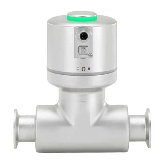
Type 8098 Description DESCRIPTION Structure The Type 8098 flowmeter is made up of a transmitter and a Type S097 flow sensor. Status indicator and seal Electrical connection Grounding connection (protective earth) Transmitter Seal Sensor housing Process connection Figure 1: Description 5.1.1 Transmitter variants Variants: • Without outputs • With 2 outputs that can be configured as analogue or digital outputs 5.1.2 Unlocking magnetic key The device is delivered with a magnetic key to unlock the transmitter. Figure 2: Unlocking magnetic key english... - Page 24 Type 8098 Description Type label, adhesive label 8098 FLOWave S Supply: 12-35 2.5W Max. IP65 / IP67 / NEMA4X Ambient Temp : –10 to 70°C CAN_H SN 999999 88888888 CAN_L CAN shield W49MN Made in France 28-06 28-06 1. Operating voltage 8. Serial number 2. Type 9.
- Page 25 Type 8098 Description Type label lasered CAN_H CAN_L Type: 8098 FLOWave S 5 pole M12 CAN shield ID: 00571790 | S/N: 001000 W4ZAL F-67220 Triembach Buerkert Made in France Supply: 12...35V ; 2,5W Max IP65 | IP67 | NEMA 4X ® Ambient Temp.:–10°...+70°C 28-06 28-06 Measuring Equipment...
-
Page 26: Certification Markings
Type 8098 Description Certification markings Certification markings are either located on the Type label of the device or on separate labels. Marking of the Unique Serial Number (USN) The USN is marked on the side of the sensor. The USN is built with the order number and the serial number of the device. Description of the status indicator As a default setting, the status indicator shows: •... -
Page 27: Technical Data
Type 8098 Technical data TECHNICAL DATA Operating conditions Ambient temperature –10 °C...+70 °C Air humidity < 85 %, non condensing Operating altitude Up to 2000 m above sea level Operating mode Continuous operation Device mobility Fixed device Indoor and outdoor (with protection against electromagnetic interference, ultraviolet rays and weather conditions) Installation category Category I according to UL/EN 61010-1 Degree of pollution Degree 2 according to UL/EN 61010-1 Degree of protection according to IEC/EN 60529 IP65/IP671) according to NEMA250... -
Page 28: Conformity To The Pressure Equipment Directive
Type 8098 Technical data 6.3.1 Conformity to the Pressure Equipment Directive → Make sure that the device materials are compatible with the liquid. → Make sure that the DN and the PN of the device are adapted for the device. The device conforms to Article 4, Paragraph 1 of the Pressure Equipment Directive 2014/68/EU under the following conditions: Device used on a pipe (PS = maximum admissible pressure in bar; DN = nominal diameter of the pipe) - Page 29 Type 8098 Technical data 6.3.3 EHEDG certification • EL class I • The following versions are EHEDG certified: Process connections Diameters Clamp2) connections according to ASME BPE 3/8", 1/2", 3/4", 1", 1 1/2", 2" (DIN 32676 series C) Clamp connections according to DIN 11864-3 series C 1/2", 3/4", 1", 1 1/2", 2" Flange connections according to DIN 11864-2 series C 1/2", 3/4", 1", 1 1/2", 2" Clamp2) connections according to DIN 32676 series B DN08, DN15 (except variants with a clamp diameter of 34.0 mm) DN25, DN40, DN50, DN65, DN80 Clamp2) connections according to DIN 32676 series A DN08, DN15, DN25, DN40, DN50, DN65, DN80 Clamp connections according to DIN 11864-3 series A, DN08, DN15, DN25, DN40, DN50...
- Page 30 Type 8098 Technical data Liquid data Ambient temperature °C Temperatures authorized for a limited duration °C Liquid temperature Figure 7: Dependency between the liquid temperature and the ambient temperature Liquid temperature – 20 °C...+110 °C, with clamp process connections. Up to 140 °C for maximum 60 minutes for a sterilisation process. Maximum temperature gradient: 10 °C/s [measured by the sensor integrated in the device] The maximum liquid temperature can be restricted by the ambient operating temperature.
- Page 31 Type 8098 Technical data Size of the process Standards the process connections Type of process connection connection conform to 3/8", 1/2", 3/4", 1", clamp ASME BPE (DIN 32676 series C) PN25 1 1/2" 1/2", 3/4", 1", 1 1/2" clamp DIN 11864-3 series C PN25 flange DIN 11864-2 series C PN25 DN40 clamp DIN 11864-3 series B PN16 DIN 32676 series B DIN 11864-3 series A PN25 DIN 32676 series A SMS 3017 / ISO 2852 for pipes according to SMS 3008 flange DIN 11864-2 series B PN16 DIN 11864-2 series A PN25 DN50 clamp DIN 11864-3 series A PN16...
-
Page 32: Measurement Data
Type 8098 Technical data Measurement data In the current section, the term “full scale” refers to full scale of volume flow rate, i.e. the flow rate corre- sponding to 10 m/s flow velocity. 6.5.1 Volume flow rate Measurement range 0...1.7 m3/h to 0...200 m3/h, depending on the DN of the sensor Measurement deviation1) 2) for a volume flow rate ±0.4 % of the measured value between 10 % of the full scale and the full scale Measurement deviation1) 2) for a volume flow rate < ±0.08 % of the full scale between 1 % of the full scale and 10 % of the full scale Repeatability2) for a volume flow rate between 10 % of ±0.2 % of the measured value the full scale and the full scale Repeatability2) for a volume flow rate between 1 % of ±0.04 % of the full scale the full scale and 10 % of the full scale... -
Page 33: Mass Flow Rate
Type 8098 Technical data 6.5.4 Acoustic transmission factor Measurement range 10 %...120 % Resolution 0.01 % Repeatability ±2 % of the measured value Refresh time Adjustable, see chapter 14.15 Setting the refresh time. Table 9: Acoustic transmission factor measurement (optional feature) 6.5.5 Density Measurement range 0.78...1.3 g/cm3 Measurement deviation 1) ±2 % of the measured value Repeatability 1) ±1 % of the measured value Refresh time Adjustable, see chapter 14.15 Setting the refresh time. -
Page 34: Electrical Data
Type 8098 Technical data Electrical data Ambient temperature °C Temperature authorized for a limited duration Liquid temperature °C Figure 8: Minimum supply voltage depending on the ambient temperature and the liquid temperature Connections Circular plug-in connector without outputs M12 x 1, 5-pin with outputs (2x AO/DO) M12 x 1, 8-pin Operating voltage 1 2...35 V DC ±10 % The minimum supply voltage depends on the liquid temperature and the ambient operating temperature: depending on the variant of the device, see Figure 8 Filtered and regulated Safety Extra-Low Voltage circuit (SELV circuit) -
Page 35: Mechanical Data
Type 8098 Technical data Digital output Transistor NPN or PNP mode Mode: pulse on/off, threshold, frequency (configurable) 0...2000 Hz, 5...35 V DC, ≤ 700 mA Galvanically isolated, passive Overload information (diagnostics software function) Protected against overloads and polarity reversals Communication interface Connection to PC via USB-büS interface (see accessories) The büS connection of the variant with outputs is only for connection to the Bürkert Communicator for configuration and software updating of the device. Due to the lack of CAN shielding, conventional büS / CANopen communication is not recommended. -
Page 36: Installation In The Pipe
Type 8098 Installation in the pipe INSTALLATION IN THE PIPE Safety instructions DANGER Risk of injury due to electrical voltage. ▶ Before carrying out work on the system, disconnect the electrical power for all the conductors and isolate it. ▶ According to UL/EN 6101010-1: Double isolate all devices connected to the flowmeter Type 8098 from the mains and note that these are limited energy circuits for all circuits connected to the flowmeter Type 8098. ▶... - Page 37 Type 8098 Installation in the pipe CAUTION Risk of injury due to a heavy device. A heavy device can fall down during transport or during installation and cause injuries. ▶ Transport, install and dismantle a heavy device with the help of another person. ▶ Use appropriate tools. NOTICE The device will be damaged if you use a tool to turn the transmitter.
-
Page 38: Changing The Position Of The Transmitter On The Sensor
Type 8098 Installation in the pipe 7.2.1 Changing the position of the transmitter on the sensor These instructions are valid for all the versions of the device. The transmitter can have four positions on the Type S097 flow sensor. See Figure 9. Figure 9: Possible positions of the transmitter For safety reasons and to comply with standard UL 61010-1, the transmitter and the flow sensor are locked. - Page 39 → Protect this device against electromagnetic interference, ultraviolet rays and, when installed outdoors, the effects of climatic conditions. → Make sure the DN of the measurement tube is suited to the flow velocity: refer to the data sheet of the device, available at country.burkert.com. → Choose a location with enough free space to put the magnetic key against the symbol the on the device. →...
- Page 40 Type 8098 Installation in the pipe → Install the device into either horizontal, oblique or vertical pipelines. But an installation in a vertical pipeline will be better to prevent air or gas bubbles inside the measurement area. → For proper operation always ensure a totally filled measurement tube. → To allow proper self-draining and to respect the 3A and EHEDG requirements, install the device into a pipeline with a minimum angle against the horizontal. See Table 12.
-
Page 41: Before Installing The Device Into The Pipe
Type 8098 Installation in the pipe → To make sure the internal temperature of the transmitter does not exceed the authorized maximum value, install the device as recommended in Figure 11. Not recommended Recommended8) Recommended8) 3) These orientations are valid for all the positions of the transmitter on the Type S097 flow sensor. Refer to Figure 9: Possible positions of the transmitter Figure 11: Orientation of a device to avoid effects of high liquid temperatures Installing the device into the pipe... -
Page 42: Installing A Device With Clamp Connections
Type 8098 Installation in the pipe 7.4.2 Installing a device with clamp connections The manufacturer of the device does not supply any gaskets for the process connections. → If the installation must be EHEDG-compliant and the device is fitted with clamp connections according to ASME BPE (DIN 32676 series C), DIN 32676 series A, DIN 32676 series B or SMS 3017 / ISO 2852 for pipes according to SMS 3008, then use EHEDG-compliant gaskets from Combifit International B.V. → To make sure you use EHEDG-compliant gaskets, refer to the "EHEDG Position Paper" available on the EHEDG website. - Page 43 Type 8098 Installation in the pipe 7.4.4 Installing a device with threaded connections according to DIN 11851 series A. Required connection parts according to DIN 11851 and corresponding DN: • 2 weld liners • 2 gaskets • 2 nuts For EHEDG conformity and threaded connections according to DIN 11851 Series A for pipes to DIN 11850: →...
-
Page 44: Electrical Installation
Type 8098 Electrical installation ELECTRICAL INSTALLATION Safety instructions DANGER Risk of injury due to electrical voltage. ▶ Before carrying out work on the system, disconnect the electrical power for all the conductors and isolate it. ▶ According to UL/EN 6101010-1: Double isolate all devices connected to the flowmeter Type 8098 from the mains and note that these are limited energy circuits for all circuits connected to the flowmeter Type 8098. ▶ Observe all applicable accident protection and safety regulations for electrical equipment. Risk of injury due to high pressure in the installation. -
Page 45: Additional Documentation
→ Do not install the cables near high voltage or high frequency cables; if this cannot be avoided, observe a minimum distance of 30 cm. Additional documentation For more information on the device via büS, see the "Cabling guide for büS/EDIP" at country.burkert.com. For more information on CANopen which is related to the device, refer to the operating instructions "CANopen Network configuration" at country.burkert.com. -
Page 46: Connecting The Device To A Power Supply
Type 8098 Electrical installation Connecting the device to a power supply The device is wired in the factory to be easily energized through the M12 male connector. → Variant without outputs: connect the device to a 12...35 V DC power supply through the 5-pin M12 male connector; Refer to chapter 8.4. → Variant with outputs: connect the device to a 12...35 V DC power supply through the 8-pin M12 male connector; Refer to chapter 8.5. The minimum voltage to be supplied depends on the liquid temperature and on the ambient operating tem- perature: see Figure 13. Ambient temperature °C Temperature authorized for a limited duration Liquid temperature °C Figure 13:... - Page 47 Type 8098 Electrical installation Connecting the device without outputs to a büS / CANopen network → For a correct operation of the device, use a 5-pin M12 female connector in stainless steel with shield connection. The büS cable that is available from Bürkert has an external diameter of 8.2 mm. → Make sure that the büS cable passes through the 5-pin M12 female connector. →...
- Page 48 Type 8098 Electrical installation Connecting the device with outputs to a büS / CANopen network 8.5.1 Connecting output AO/DO → For a correct operation of the device, use a 8-pin M12 female connector in stainless steel with shield connection. → Observe the specifications for the cable and conductors, that are given by the manufacturer. The 8-pin M12 male connector (A-coding) is used to connect the device: •...
- Page 49 Type 8098 Electrical installation 8.5.2 Connecting output 1 ATTENTION! Danger of short circuit if output 1 is incorrectly configured. ▶ Before connecting output 1, configure the output with the Bürkert Communicator as an analogue output or digital output. (Observe the notes in the operating instructions, chapter 17.2). Output 1: Output 1 as analogue output Pin 6 Pin 5 (as sink or source) + – – 12...35 V DC 4...20 mA input at Supply voltage external instrument (example of connection in sourcing mode) Output 1 as digital output Pin 6 Pin 5...
-
Page 50: Connecting The Protective Earth
Type 8098 Electrical installation Connecting the protective earth → For a proper function of device always connect the yellow/green conductor to the grounding connection on the outer surface of the transmitter housing (see Figure 16). → Use a ring cable lug for M4 screw. →... - Page 51 Type 8098 How to do the settings HOW TO DO THE SETTINGS The device settings can be made using the Bürkert Communicator software, which must be installed on a PC. Safety instructions WARNING Risk of injury due to non-conforming adjustment. Non-conforming adjustment could lead to injury and damage the device and its surroundings. ▶...
-
Page 52: Default Settings
If you have forgotten your passwords, you can restore the default passwords with the Type 8920 Bürkert Communicator software. Refer to the related Operating Instructions. Default settings You can find the default settings of the device in the CANopen supplement for the Type 8098 at country.burkert.com. → Before making any changes to the settings, use the Bürkert Communicator software to print a pdf file with all the default settings of the device. english... - Page 53 Type 8098 Commissioning COMMISSIONING WARNING Risk of injury due to non-conforming commissioning. Non-conforming commissioning could lead to injuries and damage the device and its surroundings. ▶ Before commissioning, make sure that the staff in charge have read and fully understood the contents of the operating instructions. ▶ In particular, observe the safety recommendations and intended use. ▶ The device and the installation must only be commissioned by suitably trained staff. 10.1 Prerequisites The device is installed in the pipe. The device is electrically installed and earthed.
- Page 54 Type 8098 Commissioning → To monitor the mass flow rate, set the parameter Damping of the mass flow rate: - To measure a stable mass flow rate or to conduct a teach-in procedure depending on the mass flow rate Teach-In by mass flow rate: set the damping of the mass flow rate to Medium. Refer to chapter 14.5.2 or 14.5.3. Set the parameter Damping of the density to Medium. Refer to chapter 14.8.4. - To fill containers in a time scale typically ≥ 30 s: set an appropriate damping of the mass flow rate. Refer to chapter 14.5.2 or 14.5.3. Set the parameter Damping of the density to None. Refer to chapter 14.8.4.
- Page 55 Type 8098 Commissioning 10.3 Commissioning for detecting a change of liquid in the pipe → Adjust the Damping of the acoustic transmission factor depending on the application. → Adjust the Damping of the differentiation factor depending on the application. → Check the correct behaviour of the device with the function.
- Page 56 Advanced user büS Description Advanced user büS Advanced Installer Alarm limits, except error limits Installer Alarm limits, error limits Bürkert Quick start Installer Diagnostics Installer PDO Configuration Installer NaN Replacement Installer 11.3 Default settings You can find the default settings of the device in the CANopen supplement for the Type 8098 at country.burkert.com. → Before making any changes to the settings, use the Bürkert Communicator software to print a pdf file with all the default settings of the device. english...
- Page 57 Type 8098 General settings - Parameter 11.4 Changing the operating mode of the status indicator or switching off the status indicator By default, the status indicator gives information on the device status, according to the NAMUR NE 107 standard (NAMUR mode). The following other operating modes of the status indicator are available: • Fixed color: choose the permanent colour of the status indicator. •...
-
Page 58: Entering A Name For The Device
Type 8098 General settings - Parameter 11.5 Setting the basic parameters for identifying the device on büS The Displayed name, the Location and the Description allow you to clearly identify the device on büS. 11.5.1 Entering a name for the device The entered name will be shown on any display (e.g. -
Page 59: Entering A Description For The Device
Type 8098 General settings - Parameter 11.5.3 Entering a description for the device The description allows you to precisely identify this device. To enter a description for the device, do the following:. → Select the device in the navigation area. →... -
Page 60: Changing The Transmission Speed On The Device
Type 8098 General settings - Parameter 11.6.2 Changing the transmission speed on the device The transmission speed for the communication on the fieldbus (both büS or CANopen) must be the same for all the participants of the fieldbus. By default, the transmission speed of the device is 500 kbit/s. This transmission speed is suited for a maximum cable length of 50 m. If the cable length is higher, reduce the transmission speed of all the participants. To change the transmission speed of the device, do the following: →... -
Page 61: Deactivating The Device Internal Termination Resistor
Type 8098 General settings - Parameter 11.6.4 Deactivating the device internal termination resistor The internal termination resistor is no more available after 12/2022. If the device is not installed at the end of büS or of a CANopen fieldbus, deactivate the device internal ter- mination resistor. Max. 2 120 Ω termination resistors can equip büS or a CANopen fieldbus. To deactivate the device internal termination resistor, do the following: → Select the device in the navigation area. →... - Page 62 Type 8098 General settings - Parameter 11.6.6 Setting the digital communication for büS or for a CANopen fieldbus By default, the operating mode of the digital communication is set to Standalone and the measured process data (PDOs, process data objects) is not sent on a connected fieldbus. The other operating modes of the digital communication are büS or CANopen.
-
Page 63: Stop Sending The Measured Process Data (Pdos) To Büs Or To The Canopen Fieldbus
Type 8098 General settings - Parameter 11.6.7 Stop sending the measured process data (PDOs) to büS or to the CANopen fieldbus If the device is connected to büS or to a CANopen fieldbus and the Bus mode is set to büS or to CANopen and you want to temporarily stop sending the PDOs to büS or to the CANopen fieldbus, do the following: → Select the device in the navigation area. → General settings →... - Page 64 Type 8098 General settings - Parameter h: value of the hysteresis. A hys- teresis value that is equal to 0 means that the device reacts as soon as a limit is reached. A: low error limit (Error low) B: low warning limit (Warning low) increasing C: high warning limit (Warning...
-
Page 65: Reading Out The 2 Error Limit Values
Type 8098 General settings - Parameter 11.7.1 Reading out the 2 error limit values To read out the limits the supply voltage of the device should be in, do the following: → Select the device in the navigation area. → General settings →... - Page 66 Type 8098 General settings - Parameter 11.8 Reading out the low warning limit for the voltage of the internal battery The device has a small battery to store energy so that the time system can run for 7 days when the device is not powered.
- Page 67 Type 8098 General settings - Parameter 11.10 Disabling all the diagnostics By default, all the diagnostics events related to the process, the electronics or the sensor, the messages related to the monitoring of the process values (e.g. the flow rate) and the messages related to problems on the device and on büS are disabled. If the diagnostics are active on the device, do the following to disable them: →...
- Page 68 Type 8098 General settings - Diagnostics GENERAL SETTINGS - DIAGNOSTICS 12.1 User levels of the menu items Menu item of the General settings - Diagnostics menu Minimum user level Basic user Device status büS status Receive errors Advanced user büS status Receive errors max. Advanced user büS status Transmit errors Advanced user büS status Transmit errors max. Advanced user büS status Reset error counter Installer 12.2 Reading out data related to the device 12.2.1 Reading out the number of operating hours of the device...
-
Page 69: Reading Out The Minimum Or The Maximum Value Of The Internal Temperature Of The Device
Type 8098 General settings - Diagnostics 12.2.3 Reading out the minimum or the maximum value of the internal temperature of the device To read out the minimum or the maximum value of the internal temperature of the device since the first power-up of the device, do the following: → Select the device in the navigation area. → General settings →... -
Page 70: Reading Out The Minimum Or The Maximum Value Of The Current Consumption Of The Device
Type 8098 General settings - Diagnostics 12.2.6 Reading out the current value of the current consumption of the device To read out the value of the current consumption of the device, do the following: → Select the device in the navigation area. →... -
Page 71: Checking Whether The Date And Time Are Correct
Type 8098 General settings - Diagnostics 12.2.9 Checking whether the date and time are correct To check whether the date and time are still correct on the device, do the following: → Select the device in the navigation area. → General settings →... -
Page 72: Reading Out The Number Of Current Receive Errors
Type 8098 General settings - Diagnostics 12.3 Reading out data related to büS 12.3.1 Reading out the number of current receive errors To read out the number of current receive errors, do the following: → Select the device in the navigation area. →... -
Page 73: Reading Out The Maximum Number Of Transmit Errors Since The Last Power-Up Of The Device
Type 8098 General settings - Diagnostics 12.3.4 Reading out the maximum number of transmit errors since the last power-up of the device To read out the maximum number of transmit errors, do the following: → Select the device in the navigation area. →... - Page 74 Type 8098 General settings - Maintenance GENERAL SETTINGS - MAINTENANCE 13.1 User levels of the menu items Menu item of the General settings - Maintenance menu Minimum user level Device information Basic user Reset device Installer 13.2 Reading out some device information 13.2.1 Reading out the displayed name of the device To read out the displayed name of the device, do the following: →...
- Page 75 Type 8098 General settings - Maintenance 13.2.4 Reading out the article number of the device software To read out the article number of the device software, do the following: → Select the device in the navigation area. → General settings → Maintenance →...
-
Page 76: Reading Out The Type Number Of The Device
→ Select the device in the navigation area. → General settings → Maintenance → Device information is displayed. Manufacture date 13.2.10 Reading out the version of the embedded eds file To read out the version of the embedded eds file, do the following: → Select the device in the navigation area. → General settings → Maintenance → Device information eds version is displayed. The content of the eds file is described in the related supplement available at country.burkert.com. english... -
Page 77: Restarting The Device
Type 8098 General settings - Maintenance 13.3 Restarting or resetting the device 13.3.1 Restarting the device To restart the device, do the following: → Select the device in the navigation area. → General settings → Maintenance → Reset device → Restart Next The device restarts. -
Page 78: Saw Sensor - Parameter
User levels of the editable menu items Menu item of the SAW sensor - Parameter menu Minimum user level Stand. meas. values (standard measurement values) (additional measurement values) Add. meas. values Advanced user (diagnostics events) Diag. events Refresh time Installer 14.3 Default settings You can find the default settings of the device in the CANopen supplement for the Type 8098 at country.burkert.com. → Before making any changes to the settings, use the Bürkert Communicator software to print a pdf file with all the default settings of the device. english... -
Page 79: Giving A User Defined Name To The Measured Volume Flow Rate
Type 8098 SAW sensor - Parameter 14.4 Setting the parameters of the volume flow rate 14.4.1 Giving a user defined name to the measured volume flow rate The name is used to identify the process value in the user defined views and in all the menus where the process value is displayed. By default, the name associated to the measured volume flow rate is Volume flow. To add a user defined name to the default name, do the following: → Select the device in the navigation area. →... - Page 80 Type 8098 SAW sensor - Parameter Selected damping level is applied damping: all damping damping damping None Medium High the fluctuations of the measured values are transmitted No damping if 2 consecutive measured values vary for ±30 % Figure 22: Operation of the available damping levels Damping level (mode) Response time None • 5 s if the Refresh time is set to Long •...
-
Page 81: Activating A User-Defined Damping Of The Volume Flow Rate Values
Type 8098 SAW sensor - Parameter 14.4.3 Activating a user-defined damping of the volume flow rate values The damping makes it possible to damp the fluctuations of the measured values of the volume flow rate: • on the totalizers, • on the outputs. The damping set for an analog output comes in addition to the damping of the volume flow.*) •... -
Page 82: Deactivating The Damping Of The Volume Flow Rate Values
Type 8098 SAW sensor - Parameter 14.4.4 Deactivating the damping of the volume flow rate values By default, the volume flow rate values are not damped. But if the damping of the volume flow rate values is active, do the following to deactivate it: → Select the device in the navigation area. → SAW sensor → Parameter → Stand. meas. values → Volume flow → Damping The current settings are displayed. →... - Page 83 Type 8098 SAW sensor - Parameter h: value of the hysteresis. An hys- teresis value that is equal to 0 means that the device reacts as soon as a limit is reached. A: low error limit (Error low) B: low warning limit (Warning low) increasing C: high warning limit (Warning...
-
Page 84: Deactivating The Monitoring Of The Volume Flow Rate
Type 8098 SAW sensor - Parameter By default, the monitoring of the volume flow rate is disabled, and the diagnostics are all disabled. To activate the monitoring of the volume flow rate, do the following: → Select the device in the navigation area. → SAW sensor → Parameter → Stand. meas. values → Volume flow → Limits → Active → Select Yes. T he monitoring of the volume flow rate is active and the device status will change depending on the limits that have been set. → You can configure the behaviour of an analogue output depending on the status of the device. See chapter 17.3.3 Configuring the behaviour of an analogue output depending on the status of the device.*) →... -
Page 85: Changing The Error Limits, The Warning Limits And The Hysteresis Of The Volume Flow Rate
Type 8098 SAW sensor - Parameter 14.4.7 Changing the error limits, the warning limits and the hysteresis of the volume flow rate To change the error limits, the warning limits and the hysteresis of the volume flow rate, do the following: → Select the device in the navigation area. → SAW sensor → Parameter → Stand. meas. values → Volume flow → Limits →... -
Page 86: Resetting The Default Values Of The Error Limits, The Warning Limits And The Hysteresis Of The Volume Flow Rate
Type 8098 SAW sensor - Parameter 14.4.8 Resetting the default values of the error limits, the warning limits and the hysteresis of the volume flow rate The default values of the error limits, the warning limits and the hysteresis of the volume flow rate depend on the DN of the measurement tube: • high error value: maximum volume flow rate value authorized for the DN, • low error value: opposite value of the high error value, •... - Page 87 Type 8098 SAW sensor - Parameter 14.4.9 Enabling the cut-off function of the volume flow rate If the absolute (and possibly damped, see chap 14.4.2) measured volume flow rate is less than the cut-off value plus an hysteresis value, the volume flow rate value is set to 0: The outputs*) and the totalizers react as if the actual volume flow rate were equal to 0. Volume flow rate Cut-off + hysteresis Hysteresis = 50 % of the cut-off value Cut-off value Measured volume flow rate Displayed volume flow rate Figure 24: Operation of the cut-off function By default, the cut-off function is enabled. If the cut-off function is disabled, do the following to enable it: → Select the device in the navigation area. →...
- Page 88 Type 8098 SAW sensor - Parameter 14.4.10 Changing the cut-off value of the volume flow rate The default value of the cut-off volume flow rate is equal to 0.4 % of the full scale value. The full scale value depends on the DN of the measurement tube. To change the cut-off value of the volume flow rate, do the following: → Select the device in the navigation area. → SAW sensor → Parameter → Stand. meas. values →...
-
Page 89: Resetting The Default Values Of All The Volume Flow Rate Parameters
Type 8098 SAW sensor - Parameter 14.4.12 Resetting the default values of all the volume flow rate parameters To reset all the default values of the volume flow rate parameters, do the following: → Select the device in the navigation area. → SAW sensor → Parameter → Stand. meas. values → Volume flow → Reset to default → Finish All the volume flow rate parameters are reset. english... - Page 90 Type 8098 SAW sensor - Parameter 14.5 Setting the parameters of the mass flow rate 14.5.1 Giving a user defined name to the measured mass flow rate The name is used to identify the process value in the user defined views and in all the menus where the process value is displayed. By default, the name associated to the measured mass flow rate is Mass flow. To add a user defined name to the default name, do the following: → Select the device in the navigation area. →...
- Page 91 Type 8098 SAW sensor - Parameter Selected damping level is applied damping: all damping damping damping None Medium High the fluctuations of the measured values are transmitted No damping if 2 consecutive measured values vary for ±30 % Figure 25: Operation of the available damping levels For more information concerning the response time, refer to chapter 14.15. To set a predefined damping level of the measured mass flow rate values, do the following: → Select the device in the navigation area. →...
- Page 92 Type 8098 SAW sensor - Parameter 14.5.3 Activating a user-defined damping of the mass flow rate values The damping makes it possible to damp the fluctuations of the measured values of the mass flow rate: • on the totalizers, • on the outputs. The damping set for an analog output comes in addition to the damping of the mass flow.*) By default, the measured mass flow rate values are damped with the level Medium.
- Page 93 Type 8098 SAW sensor - Parameter 14.5.4 Deactivating the damping of the mass flow rate values By default, the mass flow rate values are not damped. But if the damping of the mass flow rate values is active, do the following to deactivate it: → Select the device in the navigation area. → SAW sensor → Parameter → Stand. meas. values → Mass flow → Damping The current settings are displayed. →...
- Page 94 Type 8098 SAW sensor - Parameter h: value of the hysteresis. An hys- teresis value that is equal to 0 means that the device reacts as soon as a limit is reached. A: low error limit (Error low) B: low warning limit (Warning low) increasing C: high warning limit (Warning...
- Page 95 Type 8098 SAW sensor - Parameter By default, the monitoring of the mass flow rate is disabled, and the diagnostics are all disabled. To activate the monitoring of the mass flow rate, do the following: → Select the device in the navigation area. → SAW sensor → Parameter → Stand. meas. values → Mass flow → Limits → Active → Select Yes. T he monitoring of the mass flow rate is active and the device status will change depending on the limits that have been set. → You can configure the behaviour of an analogue output depending on the status of the device. See chapter 17.3.3 Configuring the behaviour of an analogue output depending on the status of the device.*) → You can configure a digital output to switch every time a specific event is generated. See chapter 17.5.1 Configuring a digital output as an on/off output.
- Page 96 Type 8098 SAW sensor - Parameter 14.5.7 Changing the error limits, the warning limits and the hysteresis of the mass flow rate To change the error limits, the warning limits and the hysteresis of the mass flow rate, do the following: → Select the device in the navigation area. → SAW sensor → Parameter → Stand. meas. values → Mass flow → Limits →...
- Page 97 Type 8098 SAW sensor - Parameter 14.5.8 Resetting the default values of the error limits, the warning limits and the hysteresis of the mass flow rate The default values of the error limits, the warning limits and the hysteresis of the mass flow rate depend on the DN of the measurement tube: • high error value: maximum mass flow rate value authorized for the DN, • low error value: opposite value of the high error value, •...
- Page 98 Type 8098 SAW sensor - Parameter 14.5.9 Enabling the cut-off function of the mass flow rate If the absolute (and possibly damped, see chapter 14.5.2) measured mass flow rate is less than the cut-off value plus an hysteresis value, the mass flow rate value is set to 0: The outputs*) and the totalizers react as if the actual mass flow rate were equal to 0. Mass flow rate Cut-off + hysteresis Hysteresis = 50 % of the cut-off value Cut-off value Measured mass flow rate Displayed mass flow rate Figure 27: Operation of the cut-off function By default, the cut-off function is enabled. If the cut-off function is disabled, do the following to enable it: → Select the device in the navigation area. →...
- Page 99 Type 8098 SAW sensor - Parameter 14.5.10 Changing the cut-off value of the mass flow rate The default value of the cut-off mass flow rate is equal to 0.4 % of the full scale value. The full scale value depends on the DN of the measurement tube. To change the cut-off value of the mass flow rate, do the following: → Select the device in the navigation area. → SAW sensor → Parameter → Stand. meas. values →...
- Page 100 Type 8098 SAW sensor - Parameter 14.5.12 Resetting the default values of all the mass flow rate parameters To reset all the default values of the mass flow rate parameters, do the following: → Select the device in the navigation area. → SAW sensor → Parameter → Stand. meas. values → Mass flow → Reset to default → Finish All the mass flow rate parameters are reset. english...
-
Page 101: Giving A User Defined Name To The Measured Liquid Temperature
Type 8098 SAW sensor - Parameter 14.6 Setting the parameters of the liquid temperature 14.6.1 Giving a user defined name to the measured liquid temperature The name is used to identify the process value in the user defined views and in all the menus where the process value is displayed. By default, the name associated to the measured liquid temperature is Temperature. To add a user defined name to the default name, do the following: →... - Page 102 Type 8098 SAW sensor - Parameter Selected damping level is applied None damping: all damping Medium damping High damping the fluctuations of the measured values are transmitted No damping if 2 consecutive measured values vary for ±20 °C Figure 28: Operation of the available damping levels Damping level Response time None 0 s 1 s Medium 10 s High...
-
Page 103: Activating A User-Defined Damping Of The Liquid Temperature Values
Type 8098 SAW sensor - Parameter 14.6.3 Activating a user-defined damping of the liquid temperature values The damping makes it possible to damp the fluctuations of the measured values of the liquid temperature: on the outputs. The damping of the liquid temperature comes in addition to the damping set for each analog output (see chapter 17.3.2 Selecting the damping level of the values transmitted on an analogue output).*) By default, the measured liquid temperature values are not damped. -
Page 104: Deactivating The Damping Of The Liquid Temperature Values
Type 8098 SAW sensor - Parameter 14.6.4 Deactivating the damping of the liquid temperature values By default, the liquid temperature values are not damped. But if the damping of the liquid temperature values is active, do the following to deactivate it: →... -
Page 105: Activating The Monitoring Of The Liquid Temperature
Type 8098 SAW sensor - Parameter 14.6.5 Activating the monitoring of the liquid temperature If the temperature sensor is defective, the monitoring of the liquid temperature has no effect. In that case: The message No temperature sensor detected is displayed. Because of a malfunction in the process, the measured liquid temperature value can be too high or too low. A monitored value can be: •... -
Page 106: Deactivating The Monitoring Of The Liquid Temperature
Type 8098 SAW sensor - Parameter 14.6.6 Deactivating the monitoring of the liquid temperature By default, the liquid temperature values are not monitored. If the monitoring of the liquid temperature is active, do the following to deactivate it: → Select the device in the navigation area. →... -
Page 107: Resetting The Default Values Of The Error Limits, The Warning Limits And The Hysteresis Of The Liquid Temperature
Type 8098 SAW sensor - Parameter 14.6.8 Resetting the default values of the error limits, the warning limits and the hysteresis of the liquid temperature The default values of the error limits, the warning limits and the hysteresis of the liquid temperature are: •... -
Page 108: Giving A User Defined Name To The Measured Liquid Velocity
Type 8098 SAW sensor - Parameter 14.7 Setting the parameters of the liquid velocity 14.7.1 Giving a user defined name to the measured liquid velocity The name is used to identify the process value in the user defined views and in all the menus where the process value is displayed (for example in the Outputs menu). By default, the name associated to the measured liquid velocity is Liquid velocity. To add a user defined name to the default name, do the following: →... - Page 109 Type 8098 SAW sensor - Parameter Selected damping level is applied damping: all damping damping damping None Medium High the fluctuations of the measured values are transmitted No damping if 2 consecutive measured values vary for ±30 % Figure 29: Operation of the available damping levels Response time which is associated with the damping level Damping level chosen for the volume flow plus...
-
Page 110: Activating A User-Defined Damping Of The Liquid Velocity Values
Type 8098 SAW sensor - Parameter 14.7.3 Activating a user-defined damping of the liquid velocity values The damping makes it possible to damp the fluctuations of the measured values of the liquid velocity: On the outputs. The damping of the liquid velocity comes in addition to the damping set for each analog output (see chapter 17.3.2 Selecting the damping level of the values transmitted on an analogue output).*) By default, the measured liquid velocity values are not damped. -
Page 111: Deactivating The Damping Of The Liquid Velocity Values
Type 8098 SAW sensor - Parameter 14.7.4 Deactivating the damping of the liquid velocity values By default, the liquid velocity values are not damped. But if the damping of the liquid velocity values is active, do the following to deactivate it: →... -
Page 112: Deactivating The Monitoring Of The Liquid Velocity
Type 8098 SAW sensor - Parameter To activate the monitoring of the liquid velocity, do the following: → Select the device in the navigation area. → SAW sensor → Parameter → Stand. meas. values → Liquid velocity → Limits → Active → Select Yes. The monitoring of the liquid velocity is active and the device status will change depending on the limits that have been set. -
Page 113: Changing The Error Limits, The Warning Limits And The Hysteresis Of The Liquid Velocity
Type 8098 SAW sensor - Parameter 14.7.7 Changing the error limits, the warning limits and the hysteresis of the liquid velocity To change the error limits, the warning limits and the hysteresis of the liquid velocity, do the following: → Select the device in the navigation area. →... -
Page 114: Resetting The Default Values Of All The Liquid Velocity Parameters
Type 8098 SAW sensor - Parameter To reset the default values of the error limits, the warning limits and the hysteresis of the liquid velocity, do the following: → Select the device in the navigation area. → SAW sensor → Parameter →... - Page 115 Type 8098 SAW sensor - Parameter 14.8 Setting the parameters of the liquid density 14.8.1 Giving a user defined name to the measured liquid density The name is used to identify the process value in the user defined views and in all the menus where the process value is displayed (for example in the Outputs menu). By default, the name associated to the measured liquid density is Density. To add a user defined name to the default name, do the following: →...
- Page 116 Type 8098 SAW sensor - Parameter Selected damping level is applied damping: all damping damping damping None Medium High the fluctuations of the measured values are transmitted No damping if 2 consecutive measured values vary for ±30 % Figure 30: Operation of the available damping levels Response time which is associated with the damping level Damping level chosen for the density None...
- Page 117 Type 8098 SAW sensor - Parameter 14.8.3 Activating a user-defined damping of the liquid density values The damping of the liquid density comes in addition to the damping set for the mass flow rate. The damping makes it possible to damp the fluctuations of the measured values of the liquid density: On the outputs. The damping of the liquid density comes in addition to the damping set for each analog output (see chapter 17.3.2 Selecting the damping level of the values transmitted on an analogue output).*) By default, the liquid density values are damped with the level Medium.
- Page 118 Type 8098 SAW sensor - Parameter 14.8.4 Deactivating the damping of the liquid density values By default, the liquid density values are damped with the level Medium. But if the damping of the liquid density values is active, do the following to deactivate it: →...
- Page 119 Type 8098 SAW sensor - Parameter To activate the monitoring of the liquid density, do the following: → Select the device in the navigation area. → SAW sensor → Parameter → Stand. meas. values → Density → Limits → Active → Select Yes. The monitoring of the liquid density is active and the device status will change depending on the limits that have been set.
- Page 120 Type 8098 SAW sensor - Parameter 14.8.7 Changing the error limits, the warning limits and the hysteresis of the liquid density To change the error limits, the warning limits and the hysteresis of the liquid density, do the following: → Select the device in the navigation area. →...
- Page 121 Type 8098 SAW sensor - Parameter → Reset to default → Finish The limit values and the hysteresis value are reset. 14.8.9 Setting the measurement mode of liquid density Density mode can be selected through the following values: • Measured (value measured via SAW signals, and liquid temperature) •...
-
Page 122: Giving A User Defined Name To Each Totalizer
Type 8098 SAW sensor - Parameter 14.9 Setting the parameters of the volume totalizers 14.9.1 Giving a user defined name to each totalizer The name is used to identify the process value in the user defined views and in all the menus where the process value is displayed. By default, the names associated to the volume totalizers are Totalizer 1 and Totalizer 2. To add a user defined name to the default name of a volume totalizer, do the following: → Select the device in the navigation area. →... - Page 123 Type 8098 SAW sensor - Parameter 14.9.3 Activating the monitoring of each volume totalizer value A monitored value can be: • in the normal operating range • in the warning range • in the error range You can set 4 limit values: 2 error limits and 2 warning limits. →...
- Page 124 Type 8098 SAW sensor - Parameter 14.9.4 Deactivating the monitoring of each volume totalizer By default, the volume totalizers are not monitored. If the monitoring of a volume totalizer is active, do the following to deactivate it: → Select the device in the navigation area. → SAW sensor → Parameter → Stand. meas. values → Totalizer 1 Totalizer 2 → Limits → Active → Select No. The monitoring of the volume totalizer is inactive. 14.9.5 Changing the error limits, the warning limits and the hysteresis of each volume totalizer...
- Page 125 Type 8098 SAW sensor - Parameter 14.9.6 Resetting the default values of the error limits, the warning limits and the hysteresis of each volume totalizer The default values of the error limits, the warning limits and the hysteresis of the volume totalizers are the following: • high error value: 10,000,000 m3 • low error value: –10,000,000 m3 • high warning value: 8,000,000 m3 • low warning value: –8,000,000 m3 • value of the hysteresis: 0.0 m3 To reset the default values of the error limits, the warning limits and the hysteresis of each volume totalizer, do the following: → Select the device in the navigation area. →...
- Page 126 Type 8098 SAW sensor - Parameter 14.9.8 Disabling the user to start, stop or reset each volume totalizer By default, the user is not allowed to start, to stop or to reset a volume totalizer. If the Start/Stop/Reset of a volume totalizer is active, do the following to disable them: → Select the device in the navigation area. → SAW sensor → Parameter → Stand. meas. values → Totalizer 1 Totalizer 2 → Start/Stop/Reset →...
- Page 127 Type 8098 SAW sensor - Parameter 14.9.11 Resetting each volume totalizer to a Preset value If the Start/Stop/Reset of a volume totalizer is active, do the following to reset the volume totalizer to the Preset value: → Select the device in the navigation area. → SAW sensor → Parameter → Stand. meas. values → Totalizer 1 Totalizer 2 → Value reset → Finish The volume totalizer is reset to the preset value. →...
- Page 128 Type 8098 SAW sensor - Parameter 14.9.13 Resetting the overflow counter of a volume totalizer If a volume totalizer reaches its maximum value, the associated overflow counter value is incremented by 1. To reset the overflow counter associated to each volume totalizer, do the following: → Select the device in the navigation area. → SAW sensor → Parameter → Stand. meas. values → Totalizer 1 Totalizer 2 → Reset overflow counter → Finish The overflow counter associated to the volume totalizer is reset. 14.9.14 Resetting all the parameters of a volume totalizer to the default values To reset all the parameters of a volume totalizer to the default values, do the following: →...
- Page 129 Type 8098 SAW sensor - Parameter 14.10 Setting the parameters of the mass totalizers 14.10.1 Giving a user defined name to each mass totalizer The name is used to identify the process value in the user defined views and in all the menus where the process value is displayed. By default, the names associated to the mass totalizers are Mass totalizer 1 and Mass totalizer 2. To add a user defined name to the default name of a mass totalizer, do the following: → Select the device in the navigation area. →...
- Page 130 Type 8098 SAW sensor - Parameter 14.10.3 Activating the monitoring of each mass totalizer value A monitored value can be: • in the normal operating range • in the warning range • in the error range You can set 4 limit values: 2 error limits and 2 warning limits. →...
- Page 131 Type 8098 SAW sensor - Parameter 14.10.4 Deactivating the monitoring of each mass totalizer By default, the mass totalizers are not monitored. If the monitoring of a mass totalizer is active, do the following to deactivate it: → Select the device in the navigation area. → SAW sensor → Parameter → Stand. meas. values → Mass totalizer 1 Mass totalizer 2 → Limits → Active → Select No. The monitoring of the mass totalizer is inactive. 14.10.5 Changing the error limits, the warning limits and the hysteresis of each mass totalizer To change the error limits, the warning limits and the hysteresis of each mass totalizer, do the following:...
- Page 132 Type 8098 SAW sensor - Parameter 14.10.6 Resetting the default values of the error limits, the warning limits and the hysteresis of each mass totalizer The default values of the error limits, the warning limits and the hysteresis of the mass totalizers are the following: • high error value: 10,000,000 t • low error value: –10,000,000 t • high warning value: 8,000,000 t • low warning value: –8,000,000 t • value of the hysteresis: 0.0 t To reset the default values of the error limits, the warning limits and the hysteresis of each mass totalizer, do the following: → Select the device in the navigation area. →...
- Page 133 Type 8098 SAW sensor - Parameter 14.10.8 Disabling the user to start, stop or reset each mass totalizer By default, the user is not allowed to start, to stop or to reset a mass totalizer. If the Start/Stop/Reset of a mass totalizer is active, do the following to disable them: → Select the device in the navigation area. → SAW sensor → Parameter → Stand. meas. values → Mass totalizer 1 Mass totalizer 2 → Start/Stop/Reset →...
- Page 134 Type 8098 SAW sensor - Parameter 14.10.11 Resetting each mass totalizer to a Preset value If the Start/Stop/Reset of a mass totalizer is active, do the following to reset the totalizer to the Preset value: → Select the device in the navigation area. → SAW sensor → Parameter → Stand. meas. values → Mass totalizer 1 Mass totalizer 2 → Value reset → Finish The mass totalizer is reset to the preset value. →...
- Page 135 Type 8098 SAW sensor - Parameter 14.10.13 Resetting the overflow counter of a mass totalizer If a mass totalizer reaches its maximum value, the associated overflow counter value is incremented by 1. To reset the overflow counter associated to each mass totalizer, do the following: → Select the device in the navigation area. → SAW sensor → Parameter → Stand. meas. values → Mass totalizer 1 Mass totalizer 2 → Reset overflow counter → Finish The overflow counter associated to the mass totalizer is reset. 14.10.14 Resetting all the parameters of a mass totalizer to the default values To reset all the parameters of a mass totalizer to the default values, do the following: →...
- Page 136 Type 8098 SAW sensor - Parameter 14.11 Setting the parameters of the differentiation factor (optional feature) 14.11.1 What is the differentiation factor? The differentiation factor (DF) is a dimensionless measurement value which can be used to identify the liquid flowing through the pipe. Before SW version 05.00.00, differentiation factor was named density factor. Given the fact that the option density appeared, the name was changed in order to avoid confusion. The DF is a non-calibrated acoustic measurement based on the measurement of the speed of sound in the liquid and can be compensated by temperature.
- Page 137 Type 8098 SAW sensor - Parameter 14.11.3 Activating the damping of the differentiation factor values and selecting a predefined damping level The damping makes it possible to damp the fluctuations of the measured values of the DF: • On the totalizers • On the outputs. The damping set for an analog output comes in addition to the damping of the DF. *) The damping is not applied to the new measured value, if the 2 following conditions are met: •...
- Page 138 Type 8098 SAW sensor - Parameter To set a predefined damping level of the DF, do the following: → Select the device in the navigation area. → SAW sensor → Parameter → Add. meas. values → → Damping The current settings are displayed. → Select a damping level between Low, Medium High The new settings are displayed. →...
- Page 139 Type 8098 SAW sensor - Parameter To set your own damping parameters of the measured DF values, do the following: → Select the device in the navigation area. → SAW sensor → Parameter → Add. meas. values → → Damping The current settings are displayed. →...
- Page 140 Type 8098 SAW sensor - Parameter 14.11.6 Activating the monitoring of the differentiation factor → Before activating the monitoring of the DF, set the DF error and warning limits. See chapter 14.11.8. By default, the monitoring of the DF and the diagnostics are all disabled. To activate the monitoring of the DF, do the following: → Select the device in the navigation area. →...
- Page 141 Type 8098 SAW sensor - Parameter 14.11.8 Changing the error limits, the warning limits and the hysteresis of the differentiation factor A monitored value can be: • in the normal operating range • in the warning range • in the error range You can set 4 limit values: 2 error limits and 2 warning limits.
- Page 142 Type 8098 SAW sensor - Parameter 14.11.9 Resetting the default values of the error limits, the warning limits and the hysteresis of the differentiation factor The default values of the error limits, the warning limits and the hysteresis of the DF are the following: •...
-
Page 143: Setting The Temperature Compensation For A Liquid Other Than Water
Type 8098 SAW sensor - Parameter 14.11.11 Setting the temperature compensation for a liquid other than water You can set the 5 constants (a ...a ) of the equation which compensates the temperature of the liquid to calculate the DF: + a T + a T2 + a... -
Page 144: Activating The Temperature Compensation For Water
Type 8098 SAW sensor - Parameter 14.11.12 Activating the temperature compensation for water To activate the temperature compensation for water, do the following: → Select the device in the navigation area. → SAW sensor → Parameter → Add. meas. values → → Compensation The current settings are displayed. - Page 145 Type 8098 SAW sensor - Parameter 14.11.14 Use case example of the differentiation factor If different liquids with different DF may flow through the pipe, you can identify the liquid flowing through the pipe at a given time. Liquid 1 Liquid 3 Liquid 2 Liquid 2 DF range for liquid 3 DF range for liquid 2 DF range for liquid 1 Time Figure 32: Ranges of the DF for different liquids flowing through the pipe...
-
Page 146: What Is The Acoustic Transmission Factor
Type 8098 SAW sensor - Parameter 14.12 Setting the parameters of the acoustic transmission factor (optional feature) 14.12.1 What is the acoustic transmission factor? The acoustic transmission factor makes it possible to know the quality of the transmission of sound in the liquid thus the reliability of the measurements. -
Page 147: Giving A User Defined Name To The Measured Acoustic Transmission Factor
Type 8098 SAW sensor - Parameter 14.12.2 Giving a user defined name to the measured acoustic transmission factor The name is used to identify the process value in the user defined views and in all the menus where the process value is displayed (for example in the Outputs menu). By default, the name associated to the measured acoustic transmission factor is Acoustic transmis.. To add a user defined name to the default name, do the following: →... - Page 148 Type 8098 SAW sensor - Parameter Selected damping level is applied damping: all damping damping damping None Medium High the fluctuations of the measured values are transmitted No damping if 2 consecutive measured values vary for ±30 % Figure 33: Operation of the available damping levels Damping level Response time None 0 s 1 s Medium 10 s High...
- Page 149 Type 8098 SAW sensor - Parameter 14.12.4 Activating a user-defined damping of the acoustic transmission factor The damping makes it possible to damp the fluctuations of the measured values of the acoustic trans- mission factor: • On the totalizers • On the outputs. The damping of the acoustic transmission factor comes in addition to the damping set for each analog output *) By default, the measured acoustic transmission factor values are not damped.
-
Page 150: Changing The Error Limits, The Warning Limits And The Hysteresis Of The Acoustic Transmission Factor
Type 8098 SAW sensor - Parameter 14.12.5 Deactivating the damping of the acoustic transmission factor By default, the acoustic transmission factor are not damped. If the damping of the acoustic transmission factor is active, do the following to deactivate it: →... -
Page 151: Activating The Monitoring Of The Acoustic Transmission Factor
Type 8098 SAW sensor - Parameter 14.12.7 Activating the monitoring of the acoustic transmission factor To be informed when the concentration of gas bubbles or solid particles changes in the liquid, monitor the acoustic transmission factor. A monitored value can be: •... -
Page 152: Deactivating The Monitoring Of The Acoustic Transmission Factor
Type 8098 SAW sensor - Parameter 14.12.8 Deactivating the monitoring of the acoustic transmission factor By default, the acoustic transmission factor values are not monitored. If the monitoring of the acoustic transmission factor is active, do the following to deactivate it: →... -
Page 153: Resetting The Default Values Of All The Acoustic Transmission Factor Parameters
Type 8098 SAW sensor - Parameter 14.12.10 Resetting the default values of all the acoustic transmission factor parameters To reset all the default values of all the acoustic transmission factor parameters, do the following: → Select the device in the navigation area. →... - Page 154 Type 8098 SAW sensor - Parameter Special event in the process: Special event in the process Meaning Special condition Not totally filled The tube is not totally filled. Not all the sensors are in contact with the liquid. If the parameter is set Refresh time to Very short, the event Not totally filled cannot be monitored. Liquid out of range The speed of sound in the liquid is out DN08, 3/8", 1/2": The speed of...
- Page 155 Type 8098 SAW sensor - Parameter → Do the settings for a special event (see chapter 14.13.1, 14.13.3, and 14.13.5). Is the event associated to the device The event is disabled. status None? The event cannot be signalled by an analogue output. Is the event associated to the device status Normal state1)? If the event is enabled, a message is...
- Page 156 Type 8098 SAW sensor - Parameter Are the Diagnostics active in General If the mode of the status indicator is set settings - Parameter? to NAMUR, the status indicator is white. If the mode of the status indicator is set to NAMUR, the status indicator is green.
- Page 157 Type 8098 SAW sensor - Parameter ... continued from the previous page. The status indicator is yellow. The analogue outputs react depending on the behaviour selected for Out of events.*) specification Is the event associated to the device status Out of specification? If a digital output is configured as an on/off output to switch on Out of specification events, the on/off output switches depending on the event.*)
- Page 158 Type 8098 SAW sensor - Parameter 14.13.2 Disabling the diagnostics for special events in the process By default, all the diagnostics related to the process are disabled. To disable the diagnostics for special events in the process, do the following: →...
- Page 159 Type 8098 SAW sensor - Parameter 14.13.4 Disabling the diagnostics for special events on the electronics Only for variant with outputs. By default, all the diagnostics related to the electronics are disabled. To disable the diagnostics for special events on the electronics, do the following: →...
- Page 160 Type 8098 SAW sensor - Parameter 14.13.6 Disabling the diagnostics for special events on the sensor By default, all the diagnostics related to the sensor are disabled. But if all or some diagnostics related to events occurring on the sensor are enabled, do the following to disable them all: To disable the diagnostics for the special events on the sensor, do the following: →...
- Page 161 Type 8098 SAW sensor - Parameter 14.14 Getting as accurate measurements of the volume flow rate, the mass flow rate or the liquid velocity as possible To get as accurate measurements of the volume flow rate, the mass flow rate or the liquid velocity as pos- sible, you can activate the compensation of the kinematic viscosity (in mm2/s). The following kinematic viscosity compensations are available: •...
-
Page 162: Activating The Viscosity Compensation For Water Like Liquids
Type 8098 SAW sensor - Parameter 14.14.1 Activating the viscosity compensation for water like liquids To activate the viscosity compensation of water-like liquids, do the following: → Select the device in the navigation area. → SAW sensor → Parameter → Viscosity compensation →... -
Page 163: Activating The Compensation For A Liquid With A Linear Viscosity Compensation Curve
Type 8098 SAW sensor - Parameter 14.14.3 Activating the compensation for a liquid with a linear viscosity compensation curve To activate the compensation for a liquid with a viscosity that changes in a linear way with the liquid tem- perature, do the following: →... -
Page 164: Activating The Compensation For A Liquid With A Quadratic Viscosity Compensation Curve
Type 8098 SAW sensor - Parameter 14.14.4 Activating the compensation for a liquid with a quadratic viscosity compensation curve To activate the compensation for a liquid with a quadratic viscosity compensation curve, do the following: → Select the device in the navigation area. →... -
Page 165: Activating The Compensation For A Liquid With An Inverse Quadratic Viscosity Compensation Curve
Type 8098 SAW sensor - Parameter 14.14.5 Activating the compensation for a liquid with an inverse quadratic viscosity compensation curve To activate the compensation for a liquid with an inverse quadratic compensation curve, do the following: → Select the device in the navigation area. →... -
Page 166: Use Case Of The Refresh Time
Type 8098 SAW sensor - Parameter 14.15 Setting the refresh time 14.15.1 Use case of the refresh time The refresh time is the minimum time needed to update a measurement value. The refresh time has no effect on the damping of the measured values. The refresh time of the temperature values is a constant but the refresh time of the other measurement values can be adapted to the process: •... - Page 167 Type 8098 SAW sensor - Diagnostics SAW SENSOR - DIAGNOSTICS 15.1 Reading out the generated events related to the device To read out the generated events related to the monitoring of the process value limits and to the diagnostics events, and to read out the possible associated behaviour of the device, do the following: →...
- Page 168 Type 8098 SAW sensor - Diagnostics 15.4 Reading out the refresh time that has been set To read out the refresh time that has been set in chapter 14.15 Setting the refresh time, do the following: → Select the device in the navigation area. → SAW sensor → Diagnostics → Device → Refresh time The refresh time is displayed.
- Page 169 Type 8098 SAW sensor - Diagnostics 15.7 Reading out the diagnostics related to the output values Only variant with outputs. The outputs values give the values of the process values at a certain time. See chapter 17. To read out diag- nostics related to the output values, do the following: → Select the device in the navigation area. →...
- Page 170 Type 8098 SAW sensor - Diagnostics 15.10 Reading out the diagnostics events that occurred on the sensor To read out the status of the diagnostics events that occurred on the sensor, do the following: → Select the device in the navigation area. →...
-
Page 171: Default Settings
Installer Device verification Installer Simulation Installer 16.2 Default settings You can find the default settings of the device in the CANopen supplement for the Type 8098 at country.burkert.com. → Before making any change in the settings, use the Bürkert Communicator software to print a pdf file with all the default settings of the device. 16.3 Reading out device information 16.3.1 Reading out the order numbers of the device, the transmitter board and the measurement board... -
Page 172: Reading Out The Serial Numbers Of The Device, The Transmitter Board And The Measurement Board
Type 8098 SAW sensor - Maintenance 16.3.2 Reading out the serial numbers of the device, the transmitter board and the measurement board To read out the serial numbers of the device, the transmitter board and the measurement board, do the following: →... - Page 173 Type 8098 SAW sensor - Maintenance 16.3.5 Checking the correct operation of the sensor You can check the correct operation of the sensor by comparing the current measured values of some parameters with their reference values. The reference values depend on the conditions of your process: •...
- Page 174 Type 8098 SAW sensor - Maintenance - If you do not measure water at 23 °C ±5 °C (73.4 °F ±9 °F) or the liquid is not water, then use the values of the same parameter in the menu Device verification and in the PDF file. Refer to Table 24. Menu item Current measured value of the parameter in the menu Device verification and in the PDF file Acoustic transmission factor Acoustic transmission factor Amplitudes SAW signal Signal WGx yz Times of flight Table 24: Parameter values to compare if the measured liquid is not water or the water does not have a temperature of 23 °C ±5 °C (73.4 °F ±9 °F) →...
- Page 175 Type 8098 SAW sensor - Maintenance 16.3.7 Reading out the liquid type and the liquid temperature during calibration at the manufacturer To read out the type of liquid and the temperature of the liquid used for the calibration of the device at the manufacturer, do the following: →...
- Page 176 Type 8098 SAW sensor - Maintenance 16.5 Calibrating the offset value of the flow zero point Adjust this parameter: • before carrying out a teach-in procedure of the K factor • after maintenance work • if the measured flow rate is not zero whereas the flow has been stopped During the calibration: • The status indicator is orange, if the operating mode of the status indicator is set to NAMUR (ex-works setting, see chapter 11.4 Changing the operating mode of the status indicator or switching off the status indicator).
- Page 177 Type 8098 SAW sensor - Maintenance 16.6 Setting the offset value of the flow zero point Instead of setting the offset value of the flow zero point, you can calibrate it. See chapter 16.5 Calibrating the offset value of the flow zero point. To enter the offset value of the flow zero point, do the following: → Select the device in the navigation area. → SAW sensor → Maintenance → Calibration → Stand. meas. values → Flow rate → Offset →...
- Page 178 Type 8098 SAW sensor - Maintenance 16.8 Calibrating the K factor by using a teach-in procedure Before any teach-in procedure, calibrate or set the offset value flow zero point of the device. See chapter 16.5 Calibrating the offset value of the flow zero point or 16.6 Setting the offset value of the flow zero point. By default, the value of the K factor is 1.0000. The K factor should be adjusted, if the flow rate values that are measured by the device differ from the values that are measured by a reference instrument. The K factor can be: •...
-
Page 179: Calibrating The K Factor By Using A Teach-In Procedure Depending On A Known Volume
Type 8098 SAW sensor - Maintenance If the cut-off function is enabled, it is automatically deactivated. → Wait for about 30 s: the device is averaging the flow rate. → After 30 s, enter the average value of the flow rate that has been measured by the reference flowmeter. → The new settings are displayed. → Finish The new K factor is used. If the cut-off function has been automatically deactivated, it is enabled again. If the calibration fails, a message is displayed. Refer to chapter 20.9 Messages due to calibration or simulation. 16.8.2 Calibrating the K factor by using a teach-in procedure depending on a known volume →... - Page 180 Type 8098 SAW sensor - Maintenance → Stop the flow. → Select the device in the navigation area. → SAW sensor → Maintenance → Calibration → Stand. meas. values → Flow rate → K factor → Teach-in by volume The current K factor is displayed. → Start the teach-in procedure. If the cut-off function is enabled, it is automatically deactivated.
- Page 181 Type 8098 SAW sensor - Maintenance → Calibration → Stand. meas. values → Flow rate → K factor → Teach-in by Mass flow rate The current K factor is displayed. → Start the teach-in procedure. If the cut-off function is enabled, it is automatically deactivated. → Wait for about 30 s: the device is averaging the flow rate. → After 30 s, enter the average value of the flow rate that has been measured by the reference flowmeter. → The new settings are displayed. → Finish The new K factor is used.
- Page 182 Type 8098 SAW sensor - Maintenance Diameter of the measurement tube Minimum flow rate at 1 m/s Recommended volume in kg, to get an accurate K factor 3/4" 12 l/min 19 × liquid density 1" 23 l/min 38 × liquid density 1 1/2" 57 l/min 95 × liquid density 2" 106 l/min 177 × liquid density 2 1/2" 171 l/min 285 × liquid density 3" 250 l/min 417 × liquid density DN15 15 l/min 26 × liquid density...
- Page 183 Type 8098 SAW sensor - Maintenance 16.9 Resetting the flow rate calibration data to its default values To reset all the flow rate calibration data to its default values, do the following: → Select the device in the navigation area. → SAW sensor → Maintenance → Calibration → Stand. meas. values → Flow rate → Reset to default → Finish All the flow rate calibration data is reset to their default values.
- Page 184 Type 8098 SAW sensor - Maintenance 16.11 Calibrating the offset value of the liquid temperature Instead of calibrating the offset value of the liquid temperature, you can directly enter it. See chapter 16.10 Setting the offset value of the liquid temperature. To calibrate the offset value of the liquid temperature, do the following: → Make sure a reference temperature sensor is installed in the same pipe as the FLOWave and as near as possible to the FLOWave. →...
- Page 185 Type 8098 SAW sensor - Maintenance 16.12 Resetting the offset of the liquid temperature to the default value To reset the offset of the liquid temperature to the default value, do the following: → Select the device in the navigation area. → SAW sensor → Maintenance → Calibration → Stand. meas. values → Temperature → Reset to default → Finish The temperature offset is reset to its default value.
- Page 186 Type 8098 SAW sensor - Maintenance 16.14 Setting the offset value of the differentiation factor Instead of setting the offset value of the DF, you can calibrate it. See chapter 16.15. To enter an offset value for the DF, do the following: → Select the device in the navigation area. → SAW sensor → Maintenance → Calibration → Add. meas. values → DF factor → Offset → Enter value → Set the value of the offset. →...
- Page 187 Type 8098 SAW sensor - Maintenance 16.15 Calibrating the offset value of the differentiation factor → Make sure the teach-in conditions are similar to those of the process. → To get a correct calibration result, make sure that the following conditions are met during the teach-in procedure: •...
- Page 188 Type 8098 SAW sensor - Maintenance 16.16 Setting the slope value of the differentiation factor To enter a slope value for the DF, do the following: → Select the device in the navigation area. → SAW sensor → Maintenance → Calibration →...
- Page 189 Type 8098 SAW sensor - Maintenance 16.18 Calibrating the offset value of the liquid density → Make sure the teach-in conditions are similar to those of the process. → To get a correct calibration result, make sure that the following conditions are met during the teach-in procedure: •...
- Page 190 Type 8098 SAW sensor - Maintenance 16.19 Setting the slope value of the liquid density To enter a slope value for the liquid density, do the following: → Select the device in the navigation area. → SAW sensor → Maintenance → Calibration →...
- Page 191 Type 8098 SAW sensor - Maintenance → Teach-in by density The current da coefficient is displayed. → Start the teach-in procedure. If the cut-off function is enabled, it is automatically deactivated. → Let the liquid flow through the device into the tank. When the desired density is reached: → Enter the density of the liquid. The new settings are displayed. → Finish The new da coefficient is used. If the cut-off function has been automatically deactivated, it is enabled again. If the calibration fails, a message is displayed. Refer to chapter 20.9 Messages due to calibration or simulation.
- Page 192 Type 8098 SAW sensor - Maintenance 16.22 Calibrating the offset value of the acoustic transmission factor → Make sure the teach-in conditions are similar to those of the process. → In order that the calibration result is correct, make sure the following conditions are met during the teach-in procedure: •...
- Page 193 Type 8098 SAW sensor - Maintenance 16.23 Setting the slope value of the acoustic transmission factor To enter a slope value for the acoustic transmission factor, do the following: → Select the device in the navigation area. → SAW sensor → Maintenance →...
- Page 194 Type 8098 SAW sensor - Maintenance 16.25 Checking the correct behaviour of the device The feature allows you to check if the device has the expected behaviour depending on the settings you have made. You can check the behaviour of the device: •...
-
Page 195: Checking The Behaviour Of The Device By Simulating An Event
Type 8098 SAW sensor - Maintenance 16.25.2 Checking the behaviour of the device by simulating an event The events Low flow cut off and Backward flow can only be tested by simulating a flow rate value. See chapter 16.25.1. To check the behaviour by simulating one or several events that are enabled on the device, do the following: →... - Page 196 Chapter only valid for variants with outputs. The output parameters can be set with the user level. Installer 17.1 Default settings You can find the default settings of the device in the CANopen supplement for the Type 8098 at country.burkert.com. → Before making any change in the settings, use the Bürkert Communicator software to print a pdf file with all the default settings of the device. 17.2 Changing the type of an output NOTICE Risk of short-circuit if the configuration of the output is wrong.
- Page 197 Type 8098 Outputs - Parameter To change the type of the output, do the following: → Select the device in the navigation area. → Outputs → Parameter → Output x type → Select the type of the output. The type of the output is changed. english...
-
Page 198: Changing The Process Value And The Process Value Range Associated To An Analogue Output
Type 8098 Outputs - Parameter 17.3 Setting the parameters of an analogue output By default, the device has 1 digital output and 1 analogue output, Output 1:digital and Output 3:analog. You can change the type of the outputs: see chapter 17.2. The following parameters can be set: • the Process value associated to the analogue output. •... - Page 199 Type 8098 Outputs - Parameter 17.3.2 Selecting the damping level of the values transmitted on an analogue output The following diagram shows the effect of the damping on the flow rate measurements. Volume flow rate measurement The set damping level for the volume flow rate measurements is applied (see chapter 14.4.2) The calculated volume The resulting volume If active, cut-off is applied. is used by the totalizers flow rate is displayed. and the pulse outputs. The set damping level for the ana- logue outputs is applied The resulting volume flow rate value...
-
Page 200: Configuring The Behaviour Of An Analogue Output Depending On The Status Of The Device
Type 8098 Outputs - Parameter To change the damping level of the values transmitted on an analogue output, do the following: → Select the device in the navigation area. → Outputs → Parameter → Output 1: analog Output 3: analog → Damping → Select the damping level. The damping level is changed. - Page 201 Type 8098 Outputs - Parameter 17.4 Disabling an analogue output If an analogue output is not wired, the analogue output can be disabled to avoid the generation of the events Output 1, open loop or Output 2, open loop. To disable an analogue output, do the following: →...
- Page 202 Type 8098 Outputs - Parameter Default parameters of output 1 after activation as digital output: Parameter Default value DN of process connections all diameters Mode Pulse Max. pulse time 65 ms all diameters Max. frequency 2000 Hz all diameters Pulse mode • If the Mass flow option is not all diameters available on the device: Pulse/l...
-
Page 203: Configuring A Digital Output As An On/Off Output
Type 8098 Outputs - Parameter 17.5.1 Configuring a digital output as an on/off output An on/off output switches every time the associated event is generated. You can select between the following events: • Failure • Function check • Out of specification • Maintenance required • any event activated in the menu SAW sensor Parameter Diagnostics Process •... -
Page 204: Configuring A Digital Output As An Output With Switching Thresholds
Type 8098 Outputs - Parameter 17.5.2 Configuring a digital output as an output with switching thresholds An output with switching thresholds switches depending on two threshold process values. The output can switch either according to an hysteresis model or according to a window model. Hysteresis switching The output status changes when a threshold is reached: •... -
Page 205: Configuring A Digital Output As A Frequency Output
Type 8098 Outputs - Parameter If the high threshold is equal to the low threshold, the digital output is deactivated. → Set the value of the high threshold → Set the value of the low threshold → Select to invert the switching or not →... -
Page 206: Configuring A Digital Output As A Pulse Output
Type 8098 Outputs - Parameter 17.5.4 Configuring a digital output as a pulse output When the digital output is configured as a pulse output, it transmits: • either a number of pulses proportional to the measured volume (pulse/volume), • or 1 pulse each time a set volume of liquid has been measured by the device (volume/pulse). •... - Page 207 Type 8098 Outputs - Parameter → Select in the wanted volume units pulse/volume volume/pulse → Select pulse/mass mass/pulse in the wanted volume units → If you have selected pulse/volume, set the number of pulses to be transmitted on the digital output for either 1 litre or 1 US gallon or 1 imperial gallon.
- Page 208 Type 8098 Outputs - Diagnostics OUTPUTS - DIAGNOSTICS Chapter only valid for variants with outputs. 18.1 Analogue output: reading out the current status and the values of the current Any user can read out the following data related to an analogue output: •...
- Page 209 Type 8098 Outputs - Maintenance OUTPUTS - MAINTENANCE Chapter only valid for variants with outputs. The settings can be made with the Installer user level. 19.1 Calibrating an analogue output The analogue outputs are calibrated at the factory. To adjust the analogue output to your equipment, do the following: →...
- Page 210 Type 8098 Outputs - Maintenance 19.2 Checking the correct operation of an analogue output To check the correct operation of an analogue output, do the following: → Connect a multimeter to the analogue output you have adjusted. → Select the device in the navigation area. →...
- Page 211 Type 8098 Outputs - Maintenance 19.4 Resetting the calibration data of all the analogue outputs to the default values To reset the calibration data of all the analogue outputs to its default values, do the following: → Select the device in the navigation area. →...
- Page 212 Type 8098 Outputs - Maintenance 19.6 Checking the correct operation of a frequency output To check the correct operation of a digital output configured as a frequency output, do the following: → Connect a frequency meter to the digital output configured as a frequency output. → Energize the output. → Select the device in the navigation area. → Outputs → Maintenance → Output 2: digital or Output 3: digital, configured as a frequency output → Test → Enter a frequency value →...
-
Page 213: Maintenance And Troubleshooting
Type 8098 Maintenance and troubleshooting MAINTENANCE AND TROUBLESHOOTING 20.1 Safety instructions Risk of injury due to electrical voltage. ▶ Before carrying out work on the system, disconnect the electrical power for all the conductors and isolate it. ▶ According to UL/EN 6101010-1: Double isolate all devices connected to the flowmeter Type 8098 from the mains and note that these are limited energy circuits for all circuits connected to the flowmeter Type 8098. ▶ Observe all applicable accident protection and safety regulations for electrical equipment. Risk of injury due to high pressure in the installation. -
Page 214: Cleaning In Place (Cip) Of The Device
→ To return the device for calibration or any after sales service, use the original packaging. → Send the device back to your local Bürkert sales office. The addresses of our international sales offices are available on the internet at country.burkert.com. 20.3 Cleaning the outer surface of the device → Always use a cleaning agent compatible with the materials from which the device is made. -
Page 215: Sterilisation In Place (Sip) Of The Device
Type 8098 Maintenance and troubleshooting → Let the cleaning agent circulate through the measurement tube under the following conditions: - temperature: 50 °C...75 °C, - flow velocity: 1.5...2.1 m/s, - duration: determined by your CIP recipe → Rinse the measurement tube with water of the best quality available in the factory (ideally, water for injection or purified water) under the same conditions as the first rinse. - Page 216 Type 8098 Maintenance and troubleshooting 20.6 Troubleshooting when a message is displayed → If the message displayed on your device is not explained in the Operating Instructions, contact Bürkert. If a message has been generated: • a symbol is displayed in the information bar: see Table 34. •...
-
Page 217: Kinematic Viscosity ≤ 0. Check The Flow Viscosity Compensation's Parameters
Type 8098 Maintenance and troubleshooting 20.7 Messages when setting wrong parameters 20.7.1 Kinematic viscosity ≤ 0. Check the flow viscosity compensation's parameters Message Kinematic viscosity ≤ 0. Check the flow viscosity compensation's parameters Symbol displayed Possible cause • When activating the compensation for a liquid with a constant viscosity, you have entered a negative value of the viscosity. See chapter 14.14.2 •... - Page 218 Type 8098 Maintenance and troubleshooting 20.8.2 Message "Undervoltage detected" Message Undervoltage detected Symbol displayed Possible cause The supply voltage of the device is lower than or equal to the permitted minimum error value. See chapter 11.7 Monitoring the device supply voltage or the device temperature. →...
- Page 219 Type 8098 Maintenance and troubleshooting 20.8.5 Message "Battery voltage is below the warning limit" Message Battery voltage is below the warning limit Symbol displayed Possible cause The voltage of the battery is under the low limit value. See chapter 11.8. The battery allows the internal clock to run for 7 days at ambient tem- perature when the power supply of the device is switched off or too low.
- Page 220 Type 8098 Maintenance and troubleshooting 20.8.8 Message "Undertemperature detected" Message Undertemperature detected Symbol displayed Possible cause The internal temperature of the device is lower than the permitted minimum error value (–40 °C). See chapter 11.7 Monitoring the device supply voltage or the device temperature. →...
- Page 221 Type 8098 Maintenance and troubleshooting 20.8.11 Message "Internal message store overflow" Message Internal message store overflow Symbol displayed Possible cause The number of messages generated by the device is higher than the memory capacity. What to do? → Make sure the limits set for the monitoring of the process values are correct.
-
Page 222: Message "Measure Board Is In Boot Starter Mode, No Firmware Found N°1"
Type 8098 Maintenance and troubleshooting 20.8.15 Message "Measure board is in boot starter mode, no firmware found n°1" Message Measure board is in boot starter mode, no firmware found n°1 Symbol displayed Possible cause The firmware of the measurement board is lost or is not valid. → Start the device again. What to do? → If the error is still there, send the device back to Bürkert. 20.8.16 Message "Data returned by the measurement PCB is invalid n°1"... - Page 223 Type 8098 Maintenance and troubleshooting 20.8.19 Message "An error occurred during communication" Message An error occurred during communication Symbol displayed Possible cause The flat cable that connects the sensor to the transmitter may be damaged. → Make sure the flat cable is correctly connected. What to do? → If the cable is damaged, send the device back to Bürkert. 20.8.20 Message "Max. flow rate" Message Max. flow rate Symbol displayed...
- Page 224 Type 8098 Maintenance and troubleshooting 20.8.23 Message "Totalizer 1 started" / "Totalizer 2 started" or "Mass totalizer 1 started" / "Mass totalizer 2 started" Message Totalizer 1 started / Totalizer 2 started Mass totalizer 1 started / Mass totalizer 2 started Symbol displayed Possible cause The related totalizer / mass totalizer has been started by the user. What to do? 20.9 Messages due to calibration or simulation 20.9.1 Message "Calibration result out of range"...
- Page 225 Type 8098 Maintenance and troubleshooting 20.9.3 Message "Calibration cancelled" Message Calibration cancelled Symbol displayed Possible cause The user has interrupted a calibration of the zero flow, before the waiting time of 30 seconds has elapsed. What to do? → Do a new calibration and observe the given instructions. 20.9.4 Message "Calibration cancelled, the flow rate is less than 5% of the full scale"...
- Page 226 Type 8098 Maintenance and troubleshooting 20.9.7 Message "Test mode activated" Message Test mode activated Symbol displayed Possible cause The test of an output has been started by the user. What to do? → If needed, complete the test. 20.9.8 Message "Simulation mode active" Message Simulation mode active Symbol displayed...
- Page 227 Type 8098 Maintenance and troubleshooting 20.10.2 Message "Flow rate too low" Message Flow rate too low Symbol displayed Possible cause The flow rate value is lower than the permitted minimum error value set in chapter 14.4.7 Changing the error limits, the warning limits and the hys- teresis of the volume flow rate What to do? As soon as the flow rate returns to within the permitted range, the error is automatically reset. Message Flow rate too low Symbol displayed Possible cause The flow rate value is lower than the permitted minimum warning value set...
- Page 228 Type 8098 Maintenance and troubleshooting 20.10.4 Message "Temperature too low" Message Temperature too low Symbol displayed Possible cause The value of the liquid temperature is lower than the permitted minimum error value set in chapter 14.6.7 Changing the error limits, the warning limits and the hysteresis of the liquid temperature. What to do? As soon as the value of the liquid temperature returns to within the per- mitted range, the error is automatically reset.
- Page 229 Type 8098 Maintenance and troubleshooting 20.10.6 Message "Value totalizer 1 too low" / "Value totalizer 2 too low" or "Value mass totalizer 1 too low" / "Value mass totalizer 2 too low" Value totalizer 1 too low / Value totalizer 2 too low Message Value mass totalizer 1 too low / Value mass totalizer 2 too low Symbol displayed Possible cause The value of the totalizer / mass totalizer is lower than the permitted minimum error value set in chapter 14.9.5 Changing the error limits, the warning limits and the hysteresis of each volume totalizer What to do?
- Page 230 Type 8098 Maintenance and troubleshooting 20.10.8 Message "Fluid velocity too low" Message Fluid velocity too low Symbol displayed Possible cause The value of the liquid velocity is lower than the permitted minimum error value set in chapter 14.7.7 Changing the error limits, the warning limits and the hysteresis of the liquid velocity.
- Page 231 Type 8098 Maintenance and troubleshooting 20.10.10 Message "DF too low" Message DF too low Symbol displayed Possible cause The value of the DF is lower than the permitted minimum error value set in chapter 14.11.8 Changing the error limits, the warning limits and the hys- teresis of the differentiation factor.
- Page 232 Type 8098 Maintenance and troubleshooting 20.10.12 Message "Acoustic transmission factor too low" Message Acoustic transmission factor too low Symbol displayed Possible cause The value of the acoustic transmission factor is lower than the permitted minimum error value set in chapter 14.12.6 Changing the error limits, the warning limits and the hysteresis of the acoustic transmission factor.
- Page 233 Type 8098 Maintenance and troubleshooting 20.10.14 Message "Density too low" Message Density too low Symbol displayed Possible cause The value of the density is lower than the permitted minimum error value set in chapter 14.8.7 Changing the error limits, the warning limits and the hys- teresis of the liquid density.
- Page 234 Type 8098 Maintenance and troubleshooting 20.11 Messages due to diagnostics events 20.11.1 Message "Diagnostic is active" Message Diagnostic is active Symbol displayed Possible cause All the diagnostics are active on the device. See chapter 14.13 Diag- nostics: monitoring special events in the process, on the sensor or on the electronics. What to do? 20.11.2 Message "Diagnostic is inactive"...
- Page 235 Type 8098 Maintenance and troubleshooting 20.11.4 Message "Liquid out of range" Message Liquid out of range Symbol displayed Depends on the device status the event is associated to. Possible cause The speed of sound in the liquid is out of range. The related event must be enabled. See chapter 14.13 Diagnostics: moni- toring special events in the process, on the sensor or on the electronics.
- Page 236 Type 8098 Maintenance and troubleshooting 20.11.7 Message "Change of liquid" Message Change of liquid Symbol displayed Depends on the device status the event is associated to. Possible cause A different liquid flows in the pipe. The message is active for 10 s on the display. The related event must be enabled. See chapter 14.13 Diagnostics: moni- toring special events in the process, on the sensor or on the electronics. What to do? →...
- Page 237 Type 8098 Maintenance and troubleshooting 20.11.10 Message "AO1 open loop" or "AO3 open loop" Message AO1 open loop AO2 open loop Symbol displayed Depends on the device status the event is associated to. Possible cause There is a connection problem on the related output. The current measured in the current loop is too low compared to the expected output current.
-
Page 238: Spare Parts And Accessories
Type 8098 Spare parts and accessories SPARE PARTS AND ACCESSORIES CAUTION Risk of injury and/or damage caused by the use of unsuitable parts. Incorrect accessories and unsuitable replacement parts may cause injuries and damage the device and the surrounding area. ▶ Use only original accessories and original replacement parts from Bürkert. Spare part or accessory Order number Unlocking magnetic key... -
Page 239: Packaging, Transport
▶ Store the device in a dry place away from dust. ▶ Storage temperature of the device: –20 °C...+70 °C. DISPOSAL OF THE DEVICE Environmentally friendly disposal ▶ Follow national regulations regarding disposal and the environment. ▶ Collect electrical and electronic devices separately and dispose of them as special waste. Further information: country.burkert.com. english... - Page 240 Type 8098 english...
Need help?
Do you have a question about the FLOWave S and is the answer not in the manual?
Questions and answers