Sign In
Upload
Manuals
Brands
Burkert Manuals
Measuring Instruments
Flowave 8098
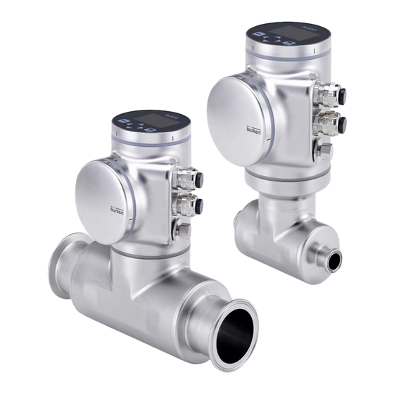
Burkert Flowave 8098 SAW Flowmeter Manuals
Manuals and User Guides for Burkert Flowave 8098 SAW Flowmeter. We have
5
Burkert Flowave 8098 SAW Flowmeter manuals available for free PDF download: Operating Instructions Manual, Quick Start Manual
Burkert Flowave 8098 Operating Instructions Manual (354 pages)
SAW Flowmeter
Brand:
Burkert
| Category:
Measuring Instruments
| Size: 5 MB
Table of Contents
General Information
5
Table of Contents
5
The Operating Instructions
6
Symbols Used
6
Definition of the Term Device
6
Definition of the Term Büs
7
Validity of the Operating Instructions
7
Intended Use
8
Device with ATEX / Iecex Certification
8
Basic Safety Information
9
General Information
11
Manufacturer's Address and International Contacts
11
Warranty Conditions
11
Information on the Internet
11
Description
13
Description
14
Device Variants
14
Unlocking Magnetic Key
16
Wi-Fi Module
16
Adhesive Labels
17
Type Labels
17
Certification Markings
19
Laser Marking
19
Marking of the Unique Serial Number (USN)
19
Marking with the MAC Address
19
Device Status Indicator
20
Technical Data
21
Operating Conditions
22
Technical Data
22
Conformity to Standards and Directives
23
Conformity to the Pressure Equipment Directive
23
UL Certification
23
ATEX / Iecex Certification
24
EHEDG Certification
24
Liquid Data
25
Measurement Data
27
Temperature
27
Volume Flow Rate
27
Acoustic Transmission Factor
28
Density
28
Differentiation Factor
28
Mass Flow Rate
28
Electrical Data
29
Mechanical Data
31
Modbus TCP Protocol
32
Specifications of the Ethernet Industrial Communication
32
PROFINET Protocol
33
Ethernet/Ip Protocol
34
Ethercat Protocol
35
Installation in the Pipe
37
Installation in the Pipe
38
Safety Instructions
38
Additional Documentation
39
Changing the Position of the Transmitter on the Sensor
39
Preparing the Device before Installation into the Pipe
39
Switching Positions of the Blind Cover and the Display Module or the Wi-Fi Module
43
Recommendations for the Installation into the Pipe
46
Before Installing the Device into the Pipe
49
Installing a Device with Clamp Connections
49
Installing a Device with Flange Connections
49
Installing the Device into the Pipe
49
Installing a Device with External-Threaded Connections According to DIN 11851 Series a for Pipes According to DIN 11850
50
Electrical Installation
51
Electrical Installation
52
Safety Instructions
52
Additional Documentation
54
Connecting the Device to a Power Supply
54
Connecting the Device to a Büs / Canopen Network
55
Activating the Device Internal Termination Resistor
57
Specifications of the Cables for the M20X1.5 Cable Glands (Device Variant with Cable Glands)
57
Specifications of the Conductors for the 12 Push-In Terminal Strip
58
Terminal Assignment of the 12 Push-In Terminal Strip
58
Opening the Front of the Transmitter
59
Wiring the Device through the M20X1.5 Cable Glands in Stainless Steel (Device Variant with Cable Glands)
61
Wiring the Device through the M20X1.5 Cable Glands in Nickel Plated Brass (Device Variant with Cable Glands)
63
Connecting The Functional Earth (Device Variant With Two M20X1.5 Cable Glands)
65
Connecting the Device to a 12
65
Variant With Cable Glands)
67
Wiring Output 1 (Analogue) And Output 3 Configured As An Analogue Output
67
Wiring Output 2 (Digital) And Output 3 Configured As A Digital Output
68
With Cable Glands)
68
Knowing the Status of the Ethernet Network (Device Variant with Two 4-Pin M12 Female Connectors - Ethernet Device Variant)
69
Connecting the Device to an Ethernet Network (Device Variant with Two 4-Pin M12 Female Connectors - Ethernet Device Variant)
70
Specifications Of The Cables And Conductors For The 4-Pin M12 Female Connectors
70
Connecting the Functional Earth (Device Variant with Two 4-Pin M12 Female Connectors - Ethernet Device Variant)
71
Doing the Settings
79
Available Software To Do The Settings
80
Connect The Device To The Bürkert Communicator Software
80
How to Do the Settings
80
Safety Instructions
80
Display Module: Description Of The User Interface
82
Description of the Display
83
Available Login User Levels
84
How to Use the Touch Sensitive Keys
84
Minimum and Maximum Values When Entering a Numerical Value
84
Default Settings
85
Menu Structure
86
Opening or Closing the Context Menu in any View (Display Module Only)
87
Adding Your Own Context Menu Items (Shortcuts, Display Module Only)
88
Changing the Login User Level if the Adjustment Is Not Protected through Passwords
89
Reading out the Messages Generated by the Device
89
Changing The Login User Level If The Adjustment Is Protected Through Passwords
90
Logging out from the Advanced User, Installer or Bürkert User Level
90
Adjusting a Percentage or Selecting a Value in a List
91
How To Navigate In The Menus And To Adjust Values
91
Reading out the Access Path to a Menu Item (Display Module Only)
91
Navigating in a Wizard and Adjusting Numbers
92
Setting Negative or Positive Numbers
93
Entering a Name
94
Activating or Deactivating a Feature
95
Menu Display
97
Display Module Settings
98
Doing The Quick
98
Safety Instructions
98
Adjusting the Brightness of the Display Backlight
99
Adjusting the Contrast of the Display
99
Menu Parameter
99
Adjusting the Activation Delay of the Screen Saver
100
Adjusting the Brightness of the Backlight by Active Screen Saver
100
Changing the Unlock Sequence of the Screen Saver
101
Unlocking the Screen Saver
101
Menu Diagnostics
102
Menu Maintenance
102
Reading out the Temperature of the Display Module
102
Reading out the Version Number of the Software of the Display Module
102
Reading out the Article Number of the Display Module
103
Reading out the Version Number of the Hardware of the Display Module
103
Reading out the Article Number of the Display Module Software
104
Reading out the Serial Number of the Display Module
104
Menu General Settings
105
Default Settings
108
General Settings - Parameter
108
Safety Instructions
108
User Levels Of The Editable Menu Items
108
Changing the Operating Mode of the Device Status Indicator
109
Changing the Operating Mode of the Device Status Indicator or Switching off the Device Status Indicator
109
Switching off the Device Status Indicator
109
Entering a Name for the Device
110
Entering the Location of the Device
110
Setting The Basic Parameters For Identifying The Device On Büs
110
Entering a Description for the Device
111
Entering a Unique Name for the Device
111
Setting the Advanced Parameters for Identifying the Device Connected to Büs or to a Canopen Bus
111
Activating the Device Internal Termination Resistor
112
Changing the Transmission Speed on the Device
112
Changing the Address of the Device Connected to a Canopen Bus
113
Deactivating the Device Internal Termination Resistor
113
Setting the Digital Communication for Büs or for a Canopen Bus
114
Monitoring The Device Supply Voltage Or The Device Temperature
115
Stop Sending the Measured Process Data (Pdos) to Büs or to the Canopen Fieldbus
115
Changing the 2 Warning Limit Values
117
Reading out the 2 Error Limit Values
117
Reading out the Hysteresis Value
117
Reading Out The Low Warning Limit For The Voltage Of The Internal Battery
118
Start-Up - Doing The Basic Settings
118
Activating The Diagnostics Function
119
Configuration Provider
120
Disabling All The Diagnostics
120
Reading Out The Status Of The Configuration Provider
121
Replacing The Data Of The Configuration Memory
122
Transferring The Configuration Data Of All The Modules
122
Changing The Date And The Time
123
Changing The Display Language
123
Activating The Adjustment Protection Through Passwords
124
Changing The Protection Passwords Of The Advanced User And Installer User Levels
124
Changing The Units Of The Physical Quantities
125
Deactivating The Adjustment Protection Through Passwords
125
Displaying The Text -- (Nan) Or A Numerical Value
126
General Settings - Diagnostics
127
Reading Out Data Related To The Device
127
Reading out the Number of Operating Hours of the Device
127
User Levels Of The Menu Items
127
Reading out the Current Value of the Internal Temperature of the Device
128
Reading out the Current Value of the Supply Voltage
128
Reading out the Minimum or the Maximum Value of the Internal Temperature of the Device
128
Reading out the Current Value of the Current Consumption of the Device
129
Reading out the Minimum or the Maximum Value of the Supply Voltage
129
Reading out the Minimum or the Maximum Value of the Current Consumption of the Device
130
Reading out the Number of Device Starts
130
Reading out the Status of the Configuration Memory
130
Checking The Voltage Of The Internal Battery
131
Checking Whether The Date And Time Are Correct
131
Reading Out Data Related To Büs
132
Reading out the Maximum Number of Receive Errors Since the Last Power-Up of the Device
132
Reading out the Number of Current Receive Errors
132
Reading out the Number of Current Transmit Errors
132
Reading out the Maximum Number of Transmit Errors Since the Last Power-Up of the Device
133
Reading out Whether the Measured Process Data (PDO, Process Data Object) Is Sent on Büs or on the Canopen Fieldbus
133
Resetting the 2 Maximum Error Counters
133
Configuration Provider Information
134
Reading out the Current Status of the Configuration Provider
134
Reading out the Number of Loaded Client (Module) Configurations
135
Reading out the Number of Managed Modules
135
Reading out the Number of Reconfigured Clients (Modules)
135
Reading out the Number of Failed Configuration Loads
136
Reading out the Number of Missing Modules
136
Erasing the Configuration Data of a Single Module
137
Reading out the Number of Failed Reconfigurations
137
General Settings - Maintenance
138
Reading Out Some Device Information
138
Reading out the Article Number of the Device
138
Reading out the Displayed Name of the Device
138
User Levels Of The Menu Items
138
Reading out the Article Number of the Device Software
139
Reading out the Serial Number of the Device
139
Reading out the Version Number of the Device Software
139
Reading out the Type Number of the Device
140
Reading out the Version Number of the Büs Software
140
Reading out the Version Number of the Device Hardware
140
Reading Out The Version Of The Embedded Eds File
141
Reading out the Manufacturing Date of the Device
141
Resetting The Device
142
Resetting the Device to All Its Factory Settings
142
Restarting the Device
142
Updating the Menu Configuration of the Device
143
Menu - Saw Sensor Parameter
145
Default Settings
150
Safety Instructions
150
Saw Sensor - Parameter
150
User Levels Of The Editable Menu Items
150
Activating the Damping of the Volume Flow Rate Values and Choosing a Predefined Damping Level
151
Giving a User Defined Name to the Measured Volume Flow Rate
151
Setting The Parameters Of The Volume Flow Rate
151
Activating a User-Defined Damping of the Volume Flow Rate Values
153
Activating the Monitoring of the Volume Flow Rate
154
Deactivating the Damping of the Volume Flow Rate Values
154
Deactivating the Monitoring of the Volume Flow Rate
156
Changing the Error Limits, the Warning Limits and the Hysteresis of the Volume Flow Rate
157
Resetting the Default Values of the Error Limits, the Warning Limits and the Hysteresis of the Volume Flow Rate
158
Enabling the Cut-Off Function of the Volume Flow Rate
159
Changing The Cut-Off Value Of The Volume Flow Rate
160
Disabling The Cut-Off Function Of The Volume Flow Rate
160
Resetting The Default Values Of All The Volume Flow Rate Parameters
161
Activating the Damping of the Mass Flow Rate Values and Choosing a Predefined Damping Level
162
Giving a User Defined Name to the Measured Mass Flow Rate
162
Setting The Parameters Of The Mass Flow Rate
162
Activating a User-Defined Damping of the Mass Flow Rate Values
165
Activating the Monitoring of the Mass Flow Rate
166
Deactivating the Damping of the Mass Flow Rate Values
166
Deactivating the Monitoring of the Mass Flow Rate
168
Changing the Error Limits, the Warning Limits and the Hysteresis of the Mass Flow Rate
169
Resetting the Default Values of the Error Limits, the Warning Limits and the Hysteresis of the Mass Flow Rate
169
Enabling the Cut-Off Function of the Mass Flow Rate
170
Changing The Cut-Off Value Of The Mass Flow Rate
171
Disabling The Cut-Off Function Of The Mass Flow Rate
172
Resetting The Default Values Of All The Mass Flow Rate Parameters
172
Activating the Damping of the Liquid Temperature Values and Choosing a Predefined Damping Level
173
Giving a User Defined Name to the Measured Liquid Temperature
173
Setting The Parameters Of The Liquid Temperature
173
Activating a User-Defined Damping of the Liquid Temperature Values
175
Activating the Monitoring of the Liquid Temperature
176
Deactivating the Damping of the Liquid Temperature Values
176
Deactivating the Monitoring of the Liquid Temperature
177
Changing the Error Limits, the Warning Limits and the Hysteresis of the Liquid Temperature
178
Resetting the Default Values of the Error Limits, the Warning Limits and the Hysteresis of the Liquid Temperature
178
Resetting the Default Values of All the Liquid Temperature Parameters
179
Giving a User Defined Name to the Measured Liquid Concentration
180
Selecting the Liquid Concentration Type
180
Setting The Parameters Of The Liquid Concentration
180
Activating the Damping of the Liquid Concentration Values and Choosing a Predefined Damping Level
181
Activating a User-Defined Damping of the Liquid Concentration Values
182
Activating the Monitoring of the Liquid Concentration
183
Deactivating the Damping of the Liquid Concentration Values
183
Deactivating the Monitoring of the Liquid Concentration
184
Changing the Error Limits, the Warning Limits and the Hysteresis of the Liquid Concentration
185
Resetting The Default Values Of All The Liquid Concentration Parameters
186
Resetting the Default Values of the Error Limits, the Warning Limits and the Hysteresis of the Liquid Concentration
186
Activating the Damping of the Liquid Velocity Values and Choosing a Predefined Damping Level
187
Giving a User Defined Name to the Measured Liquid Velocity
187
Setting The Parameters Of The Liquid Velocity
187
Activating a User-Defined Damping of the Liquid Velocity Values
189
Activating the Monitoring of the Liquid Velocity
190
Deactivating the Damping of the Liquid Velocity Values
190
Deactivating the Monitoring of the Liquid Velocity
191
Changing the Error Limits, the Warning Limits and the Hysteresis of the Liquid Velocity
192
Resetting the Default Values of the Error Limits, the Warning Limits and the Hysteresis of the Liquid Velocity
192
Resetting The Default Values Of All The Liquid Velocity Parameters
193
Activating the Damping of the Liquid Density Values and Choosing a Predefined Damping Level
194
Giving a User Defined Name to the Measured Liquid Density
194
Setting The Parameters Of The Liquid Density
194
Activating a User-Defined Damping of the Liquid Density Values
196
Activating the Monitoring of the Liquid Density
197
Deactivating the Damping of the Liquid Density Values
197
Deactivating the Monitoring of the Liquid Density
198
Changing the Error Limits, the Warning Limits and the Hysteresis of the Liquid Density
199
Resetting the Default Values of the Error Limits, the Warning Limits and the Hysteresis of the Liquid Density
199
Setting the Measurement Mode of Liquid Density
200
Resetting The Default Values Of All The Liquid Density Parameters
201
Choosing The Counting Direction Of Each Volume Totalizer
202
Giving A User Defined Name To Each Volume Totalizer
202
Setting The Parameters Of The Volume Totalizers
202
Activating The Monitoring Of Each Volume Totalizer Value
203
Changing The Error Limits, The Warning Limits And The Hysteresis Of Each
204
Deactivating The Monitoring Of Each Volume Totalizer
204
Volume Totalizer
204
Enabling The User To Start, Stop Or Reset Each Volume Totalizer
205
Resetting the Default Values of the Error Limits, the Warning Limits and the Hysteresis of each Volume Totalizer
205
Disabling The User To Start, Stop Or Reset Each Volume Totalizer
206
Starting Each Volume Totalizer
206
Stopping Each Volume Totalizer
206
Changing The Preset Value For A Volume Totalizer Reset
207
Resetting each Volume Totalizer to a Preset Value
207
Giving A User Defined Name To Each Mass Totalizer
208
Resetting All The Parameters Of Each Volume Totalizer To Their Default Values
208
Resetting The Overflow Counter Of Each Volume Totalizer
208
Setting The Parameters Of The Mass Totalizers
208
Choosing The Counting Direction Of Each Mass Totalizer
209
Activating The Monitoring Of Each Mass Totalizer Value
210
Changing the Error Limits, the Warning Limits and the Hysteresis of each Mass Totalizer
211
Deactivating The Monitoring Of Each Mass Totalizer
211
Enabling The User To Start, Stop Or Reset Each Mass Totalizer
212
Resetting the Default Values of the Error Limits, the Warning Limits and the Hysteresis of each Mass Totalizer
212
Disabling The User To Start, Stop Or Reset Each Mass Totalizer
213
Starting Each Mass Totalizer
213
Stopping Each Mass Totalizer
213
Changing The Preset Value For A Mass Totalizer Reset
214
Resetting each Mass Totalizer to a Preset Value
214
Resetting All The Parameters Of Each Mass Totalizer To Their Default Values
215
Resetting The Overflow Counter Of Each Mass Totalizer
215
Giving A User Defined Name To The Measured Differentiation Factor
216
Setting The Parameters Of The Differentiation Factor (Optional Feature)
216
What Is The Differentiation Factor
216
Activating the Damping of the Differentiation Factor Values and Choosing a Predefined Damping Level
217
Activating A User-Defined Damping Of The Differentiation Factor Values
218
Deactivating The Damping Of The Differentiation Factor Values
219
Activating The Monitoring Of The Differentiation Factor
220
Deactivating The Monitoring Of The Differentiation Factor
220
Changing the Error Limits, the Warning Limits and the Hysteresis of the Differentiation Factor
221
Resetting the Default Values of the Error Limits, the Warning Limits and the Hysteresis of the Differentiation Factor
222
Setting The Temperature Compensation For A Liquid Other Than Water
223
Setting The Temperature Compensation To Measure The Differentiation Factor
223
Activating The Temperature Compensation For Water
224
Resetting The Default Values Of All The Differentiation Factor Parameters
225
Use Case Example Of The Differentiation Factor
225
Giving A User Defined Name To The Measured Acoustic Transmission Factor
226
Setting The Parameters Of The Acoustic Transmission Factor (Optional Feature)
226
What Is The Acoustic Transmission Factor
226
Activating the Damping of the Values of the Acoustic Transmission Factor and Choosing a Predefined Damping Level
227
Activating a User-Defined Damping of the Values of the Acoustic Transmission Factor
229
Changing the Error Limits, the Warning Limits and the Hysteresis of the Acoustic Transmission Factor
230
Deactivating The Damping Of The Values Of The Acoustic Transmission
230
Activating The Monitoring Of The Acoustic Transmission Factor
231
Deactivating The Monitoring Of The Acoustic Transmission Factor
232
Resetting the Default Values of the Error Limits, the Warning Limits and the Hysteresis of the Acoustic Transmission Factor
232
Diagnostics: Monitoring Special Events that Occur in the Process, on the Sensor or on the Electronics
233
Resetting The Default Values Of All The Acoustic Transmission Factor Parameters
233
Enabling The Diagnostics For Special Events In The Process
237
Disabling The Diagnostics On A Special Event Occurring On The Electronics
238
Disabling The Diagnostics On A Special Event Related To The Process
238
Disabling The Diagnostics On A Special Event Occurring On The Sensor
239
Enabling The Diagnostics For Special Events Occurring On The Electronics
239
Enabling The Diagnostics For Special Events Occurring On The Sensor
240
Getting as Accurate Measurements of the Volume Flow Rate, the Mass Flow Rate or the Liquid Velocity as Possible
241
Activating The Compensation For A Liquid With A Constant Viscosity
242
Activating The Viscosity Compensation For Water-Like Liquids
242
Activating the Compensation for a Liquid with a Linear Viscosity Compensation Curve
243
Activating the Compensation for a Liquid with a Quadratic Viscosity Compensation Curve
244
Activating the Compensation for a Liquid with an Inverse Quadratic Viscosity Compensation Curve
245
Resetting The Default Values Of The Viscosity Compensation Parameters
246
Changing The Refresh Time
247
Setting The Refresh Time
247
Use Case Of The Refresh Time
247
Menu -Saw Sensor Diagnostics
249
Reading Out The Flow Direction That Has Been Set
250
Reading Out The Generated Events Related To The Device
250
Reading Out The Temperatures Of The Electronic Boards And Of The Liquid
250
Saw Sensor - Diagnostics
250
Reading Out The Operating Hours Of The Device
251
Reading Out The Refresh Time That Has Been Set
251
Reading Out The Diagnostics Events That Occurred In The Process
252
Reading Out The Diagnostics Related To The Output Values
252
Reading Out The Operating Hours Of The Measurement Board
252
Reading Out The Diagnostics Events That Occurred On The Electronics
253
Reading Out The Diagnostics Events That Occurred On The Sensor
253
Reading Out If A Process Value Is In The Monitored Range
254
Reading Out The Diagnostic Events Related To The Monitored Limits
254
Advertisement
Burkert Flowave 8098 Operating Instructions Manual (280 pages)
FLOWave SAW Flowmeter Software version A.02.00.00 and higher
Brand:
Burkert
| Category:
Measuring Instruments
| Size: 4 MB
Table of Contents
General Information
5
Table of Contents
5
1 About.these.operating.instructions
6
Symbols.used
6
Definition.of.the.word.device
6
Definition.of.the.word.büs
7
Validity.of.the.operating.instructions
7
2 Intended.use
7
3 Basic.safety.information
8
4 General.information
10
Manufacturer's.address.and.international.contacts
10
Warranty.conditions
10
Information.on.the.internet
10
Description
11
Description
12
Knowing.the.device
12
Wi-Fi Module
13
Unlocking Magnetic Key
14
Understanding.the.rating.plates
14
Marking.with.the.mac.address
16
Description.of.the.device.status.led
17
Technical Data
19
Conformity.to.standards.and.directives
20
Conformity.to.the.pressure.equipment.directive
20
Operating.conditions
20
Technical Data
20
Ehedg.certification
21
Ul.certification
21
Fluid.data
22
Measurement.data
24
Electrical.data
25
Mechanical.data
26
Specifications.of.the.ethernet.industrial.communication
28
Modbus TCP Protocol
28
PROFINET Protocol
28
Ethernet/Ip Protocol
29
Ethercat Protocol
31
Installation in the Pipe
33
Safety.instructions
34
Installation in the Pipe
34
Preparing.the.device.before.installation.into.the.pipe
35
Changing the Position of the Transmitter on the Sensor
35
Switching Positions of the Blind Cover and the Display Module
39
Recommendations.for.the.installation.into.the.pipe
41
Installing.the.device.into.the.pipe
44
Before Installing the Device into the Pipe
44
Installing a Device with Clamp Connections
44
Installing a Device with Flange Connections
44
Electrical Installation
45
Electrical Installation
46
Safety.instructions
46
Assembling.and.wiring.the.5-Pin.m12.Female.connector.(A-Coding)
48
Specifications.of.the.cable.for.the.5-Pin.m12.Male.connector
48
Connecting.the.device.to.a.power.supply
49
Connecting.the.device.to.a.büs./.Canopen.network
50
Activating.the.device.internal.termination.resistor.(Only.büs.network)
51
Specifications.of.the.cables.for.the.m20X1,5.Cable.glands.(Only.device.with.cable.glands)
51
Specifications.of.the.conductors.for.the.12.Push-In.terminal.strip
52
Terminal.assignment.of.the.12.Push-In.terminal.strip
52
Opening.the.front.of.the.transmitter
53
Wiring.the.device.through.the.m20X1,5.Cable.glands.in.stainless.steel
55
Glands)
55
Wiring.the.device.through.the.m20X1,5.Cable.glands.in.nickel.plated.brass
57
Cable.glands)
57
Connecting.the.functional.earth.(Device.with.2.M20X1,5.Cable.glands)
59
Connecting.the.device.to.a.12
60
(Only.device.with.cable.glands)
60
Cable.glands)
60
Wiring.output.2.(Digital).And.output.3.Configured.as.a.digital.output
62
Glands)
62
Knowing.the.status.of.the.ethernet.network
63
Ethernet.version)
63
Connecting.the.device.to.an.ethernet.network
64
Nectors.-.Ethernet.version)
64
Specifications.of.the.cables.and.conductors.for.the.4-Pin.m12.Female.connectors
64
Connecting.the.functional.earth
65
Doing the Settings
67
Safety.instructions
68
How.to.do.the.settings
68
Preparing.the.bürkert.communicator.software
68
Available.software.to.do.the.settings
68
Display.module:.description.of.the.user.interface
70
Description of the Display
71
How to Use the Touch Sensitive Keys
72
Minimum and Maximum Values When Entering a Numerical Value
72
Available.login.user.levels
72
Default.settings
73
Menu.structure
74
Opening or Closing the Context Menu in any View (Display Module Only)
75
Adding Your Own Context Menu Items (Shortcuts, Display Module Only)
76
Reading out the Messages Generated by the Device
77
Changing the Login User Level if the Adjustment Is Not Protected through Passwords
77
Changing the Login User Level if the Adjustment Is Protected through Passwords
78
Installer Bürkert
78
Reading out the Access Path to a Menu Item (Display Module Only)
79
How.to.navigate.in.the.menus.and.to.adjust.values
79
Adjusting a Percentage or Selecting a Value in a List
79
Navigating in a Wizard and Adjusting Numbers
80
Setting Negative or Positive Numbers
81
Entering a Name
82
Activating or Deactivating a Feature
83
Display Menu
85
Display.module.settings
86
Safety.instructions
86
Module.only)
86
Menu.parameter
87
Adjusting the Brightness of the Display Backlight
87
Adjusting the Contrast of the Display (Chapter Has Been Moved Here)
87
Adjusting the Activation Delay of the Screen Saver
88
Adjusting the Brightness of the Backlight by Active Screen Saver
88
Unlocking the Screen Saver
89
Changing the Unlock Sequence of the Screen Saver
89
Menu.maintenance
90
Reading out the Version Number of the Software of the Display Module
90
Reading out the Version Number of the Hardware of the Display Module
90
Reading out the Article Number of the Display Module
91
Reading out the Article Number of the Display Module Software
91
Reading out the Serial Number of the Display Module
92
Menu.diagnostics
90
Reading out the Temperature of the Display Module
90
General.settings Menu
93
Safety.instructions
96
User.levels.of.the.editable.menu.items
96
Default.settings
96
General.settings.-.Parameter
96
Changing.the.operating.mode.of.the.device.status.led.or.switching.off.the.status.led
97
Changing the Operating Mode of the Device Status LED
97
Switching off the Status LED
97
Setting.the.basic.parameters.for.identifying.the.device.on.büs
98
Entering a Name for the Device
98
Entering the Location of the Device
98
Entering a Description for the Device
99
Canopen.bus
99
Entering a Unique Name for the Device
99
Changing the Transmission Speed on the Device
100
Activating the Device Internal Termination Resistor
100
Deactivating the Device Internal Termination Resistor
101
Changing the Address of the Device Connected to a Canopen Bus
101
Setting the Digital Communication for Büs or for a Canopen Bus
102
Stop Sending the Measured Process Data (Pdos) to Büs or to the Canopen Fieldbus
103
Monitoring.the.device.supply.voltage.or.the.device.temperature
103
Reading out the 2 Error Limit Values
105
Changing the 2 Warning Limit Values
105
Reading out the Hysteresis Value
105
Start-Up.-.Doing.the.basic.settings
106
Reading.out.the.low.warning.limit.for.the.voltage.of.the.internal.battery
106
Disabling.all.the.diagnostics
107
Activating.the.diagnostics.function
107
Configuration.provider
108
Reading out the Status of the Configuration Provider
109
Replacing the Data of the Configuration Memory
109
Transferring the Configuration Data of All the Modules
110
Changing.the.date.and.the.time
110
Changing.the.display.language
111
Activating.the.adjustment.protection.through.passwords
111
Changing.the.protection.passwords.of.the.advanced.user.and.installer.user.levels
112
Deactivating.the.adjustment.protection.through.passwords
112
Changing.the.units.of.the.physical.quantities
113
User.levels.of.the.menu.items
114
Reading.out.data.related.to.the.device
114
Reading out the Number of Operating Hours of the Device
114
Reading out the Current Value of the Internal Temperature of the Device
114
Reading out the Minimum or the Maximum Value of the Internal Temperature of the Device
115
Reading out the Current Value of the Supply Voltage
115
Reading out the Minimum or the Maximum Value of the Supply Voltage
116
Reading out the Current Value of the Current Consumption of the Device
116
Reading out the Minimum or the Maximum Value of the Current Consumption of the Device
117
Reading out the Number of Device Starts
117
Reading out the Status of the Configuration Memory
117
Checking Whether the Date and Time Are Correct
118
Checking the Voltage of the Internal Battery
118
General.settings.-.Diagnostics
114
Reading.out.data.related.to.büs
119
Reading out the Number of Current Receive Errors
119
Reading out the Maximum Number of Receive Errors Since the Last Power-Up of the Device
119
Reading out the Number of Current Transmit Errors
119
Reading out the Maximum Number of Transmit Errors Since the Last Power-Up of the Device
120
Resetting the 2 Maximum Error Counters
120
Reading out Whether the Measured Process Data (PDO, Process Data Object) Is Sent on Büs or on the Canopen Fieldbus
120
Configuration.provider.information
121
Reading out the Current Status of the Configuration Provider
121
Reading out the Number of Loaded Client (Module) Configurations
122
Reading out the Number of Reconfigured Clients (Modules)
122
Reading out the Number of Managed Modules
122
Reading out the Number of Missing Modules
123
Reading out the Number of Failed Configuration Loads
123
Reading out the Number of Failed Reconfigurations
124
Erasing the Configuration Data of a Single Module
124
User.levels.of.the.menu.items
125
Reading.out.some.device.information
125
Reading out the Displayed Name of the Device
125
Reading out the Article Number of the Device
125
Reading out the Serial Number of the Device
126
Reading out the Article Number of the Device Software
126
Reading out the Version Number of the Device Software
126
Reading out the Version Number of the Büs Software
127
Reading out the Version Number of the Device Hardware
127
Reading out the Type Number of the Device
127
Reading out the Manufacturing Date of the Device
128
Reading out the Version of the Embedded Eds File
128
General.settings.-.Maintenance
125
Resetting.the.device
128
Restarting the Device
129
Resetting the Device to All Its Factory Settings
129
Updating the Menu Configuration of the Device
129
Saw.sensor Parameter Menu-
131
Default.settings
134
Saw.sensor Parameter
134
User.levels.of.the.editable.menu.items
134
Safety.instructions
134
Setting.the.parameters.of.the.volume.flow.rate
134
Giving a User Defined Name to the Measured Volume Flow Rate
134
Activating the Damping of the Volume Flow Rate Values and Choosing a Predefined Damping Level
135
Activating a User-Defined Damping of the Volume Flow Rate Values
136
Deactivating the Damping of the Volume Flow Rate Values
137
Activating the Monitoring of the Volume Flow Rate
138
Deactivating the Monitoring of the Volume Flow Rate
140
Changing the Error Limits, the Warning Limits and the Hysteresis of the Volume Flow Rate
140
Resetting the Default Values of the Error Limits, the Warning Limits and the Hysteresis of the Volume Flow Rate
141
Enabling the Cut-Off Function
142
Changing the Cut-Off Value of the Flow Rate
143
Disabling the Cut-Off Function
143
Getting as Accurate Measurements of the Volume Flow Rate or the Liquid Velocity as Possible
144
Activating the Viscosity Compensation for Water Like Liquids
144
Activating the Compensation for a Liquid with a Constant Viscosity
145
Activating the Compensation for a Liquid with a Linear Viscosity Compensation Curve
146
Activating the Compensation for a Liquid with a Quadratic Viscosity Compensation Curve
147
Activating the Compensation for a Liquid with an Inverse Quadratic Viscosity Compensation Curve
148
Resetting the Default Values of the Viscosity Compensation Parameters
149
Resetting the Default Values of All the Volume Flow Rate Parameters
149
Setting.the.parameters.of.the.liquid.temperature
150
Giving a User Defined Name to the Measured Liquid Temperature
150
Activating the Damping of the Liquid Temperature Values and Choosing a Predefined Damping Level
150
Activating a User-Defined Damping of the Liquid Temperature Values
152
Deactivating the Damping of the Liquid Temperature Values
153
Activating the Monitoring of the Liquid Temperature
153
Deactivating the Monitoring of the Liquid Temperature
154
Changing the Error Limits, the Warning Limits and the Hysteresis of the Liquid Temperature
155
Resetting the Default Values of the Error Limits, the Warning Limits and the Hysteresis of the Liquid Temperature
155
Resetting the Default Values of All the Liquid Temperature Parameters
156
Setting.the.parameters.of.the.liquid.velocity
156
Giving a User Defined Name to the Measured Liquid Velocity
156
Activating the Damping of the Liquid Velocity Values and Choosing a Predefined Damping Level
157
Activating a User-Defined Damping of the Liquid Velocity Values
158
Deactivating the Damping of the Liquid Velocity Values
159
Activating the Monitoring of the Liquid Velocity
160
Deactivating the Monitoring of the Liquid Velocity
161
Changing the Error Limits, the Warning Limits and the Hysteresis of the Liquid Velocity
161
Resetting the Default Values of the Error Limits, the Warning Limits and the Hysteresis of the Liquid Velocity
162
Resetting the Default Values of All the Liquid Velocity Parameters
162
Setting.the.parameters.of.the.totalizers
163
Giving a User Defined Name to each Totalizer
163
Choosing the Counting Direction of each Totalizer
163
Activating the Monitoring of each Totalizer Value
164
Deactivating the Monitoring of each Totalizer
165
Changing the Error Limits, the Warning Limits and the Hysteresis of each Totalizer
165
Resetting the Default Values of the Error Limits, the Warning Limits and the Hysteresis of each Totalizer
166
Enabling the User to Start, Stop or Reset each Totalizer
167
Disabling the User to Start, Stop or Reset each Totalizer
167
Starting each Totalizer
167
Stopping each Totalizer
168
Resetting each Totalizer to a Preset.value
168
Preset.value
168
Resetting the Overflow Counter of each Totalizer
169
Resetting All the Parameters of each Totalizer to Their Default Values
169
Setting.the.parameters.of.the.density.factor.(Optional.feature)
170
What Is the Density Factor
170
Giving a User Defined Name to the Measured Density Factor
170
Activating the Monitoring of the Density Factor
171
Deactivating the Monitoring of the Density Factor
172
Changing the Error Limits, the Warning Limits and the Hysteresis of the Density Factor
172
Resetting the Default Values of the Error Limits, the Warning Limits and the Hysteresis of the Density Factor
173
Setting the Temperature Compensation to Measure the Density Factor
174
Setting the Temperature Compensation for a Liquid Other than Water
174
Activating the Temperature Compensation for Water
175
Resetting the Default Values of All the Density Factor Parameters
176
Use Case Example of the Density Factor
176
Setting.the.parameters.of.the.acoustic.transmission.factor.(Optional.feature)
177
What Is the Acoustic Transmission Factor
177
Giving a User Defined Name to the Measured Acoustic Transmission Factor
177
Changing the Error Limits, the Warning Limits and the Hysteresis of the Acoustic Transmission Factor
178
Activating the Monitoring of the Acoustic Transmission Factor
179
Deactivating the Monitoring of the Acoustic Transmission Factor
180
Resetting the Default Values of the Error Limits, the Warning Limits and the Hysteresis of the Acoustic Transmission Factor
180
Resetting the Default Values of All the Acoustic Transmission Factor Parameters
181
Setting.the.diagnostics.events
181
Enabling the Diagnostics for All the Special Events in the Process
185
Disabling the Diagnostics for All the Special Events in the Process
186
Configuring the Diagnostics for Special Events in the Process and Enabling the Events One by One
186
Disabling One by One the Events Related to the Process
187
Enabling All the Diagnostics for the Events Occurring on the Electronics
187
Disabling All the Diagnostics for the Events Occurring on the Electronics
188
Disabling One by One the Events Occurring on the Electronics
188
Configuring the Diagnostics for the Events Occurring on the Electronics and Enabling the Events One by One
189
Enabling All the Diagnostics for the Events Occurring on the Sensor
189
Disabling All the Diagnostics for the Events Occurring on the Sensor
190
Disabling One by One the Events Occurring on the Sensor
190
Configuring the Diagnostics for the Events Occurring on the Sensor and Enabling the Events One by One
191
Setting.the.refresh.time
191
Use Case of the Refresh Time
191
Changing the Refresh Time
191
Saw.sensor Diagnostics Menu-
193
Reading.out.the.flow.direction.that.has.been.set
194
Reading.out.the.generated.events.related.to.the.device
194
Reading.out.the.temperatures.of.the.electronic.boards.and.of.the.liquid
194
Saw.sensor.-.Diagnostics
194
Reading.out.the.diagnostics.events.that.occurred.in.the.process
195
Reading.out.the.diagnostics.events.that.occurred.on.the.electronics
195
Reading.out.the.diagnostics.events.that.occurred.on.the.sensor
196
Reading.out.the.diagnostics.related.to.the.monitored.limits
196
Reading.out.the.diagnostics.related.to.the.monitored.limits.of.the.process.values
196
Reading.out.the.diagnostics.related.to.the.monitored.limits.of.the.totalizers
197
Reading.out.the.operating.duration.of.the.device
197
Burkert Flowave 8098 Operating Instructions Manual (241 pages)
Brand:
Burkert
| Category:
Measuring Instruments
| Size: 7 MB
Table of Contents
Symbols Used
18
Intended Use
19
Basic Safety Information
20
General Information
22
Manufacturer's Address and International Contacts
22
Warranty Conditions
22
Information on the Internet
22
Transmitter Variants
23
Unlocking Magnetic Key
23
Certification Markings
26
Technical Data
27
Operating Conditions
27
Standards and Directives
27
Conformity to the Pressure Equipment Directive
28
Measurement Data
32
Volume Flow Rate
32
Mass Flow Rate
33
Electrical Data
34
Mechanical Data
35
Installation in the Pipe
36
Safety Instructions
36
Changing the Position of the Transmitter on the Sensor
38
Before Installing the Device into the Pipe
41
Installing a Device with Clamp Connections
42
Installing a Device with Flange Connections
42
Electrical Installation
44
Additional Documentation
45
Connecting the Device to a Power Supply
46
Connecting the Protective Earth
50
Default Settings
52
Entering a Name for the Device
58
Entering the Location of the Device
58
Entering a Description for the Device
59
Entering a Unique Name for the Device
59
Changing the Transmission Speed on the Device
60
Activating the Device Internal Termination Resistor
60
Deactivating the Device Internal Termination Resistor
61
Stop Sending the Measured Process Data (Pdos) to Büs or to the Canopen Fieldbus
63
Reading out the 2 Error Limit Values
65
Changing the 2 Warning Limit Values
65
Reading out the Hysteresis Value
65
Reading out the Minimum or the Maximum Value of the Internal Temperature of the Device
69
Reading out the Current Value of the Supply Voltage
69
Reading out the Minimum or the Maximum Value of the Supply Voltage
69
Reading out the Minimum or the Maximum Value of the Current Consumption of the Device
70
Reading out the Number of Device Starts
70
Checking Whether the Date and Time Are Correct
71
Checking the Voltage of the Internal Battery
71
Reading out the Number of Current Receive Errors
72
Reading out the Maximum Number of Receive Errors Since the Last Power-Up of the Device
72
Reading out the Number of Current Transmit Errors
72
Reading out the Maximum Number of Transmit Errors Since the Last Power-Up of the Device
73
Resetting the 2 Maximum Error Counters
73
Reading out Whether the Measured Process Data (PDO, Process Data Object) Is Sent on Büs or on the Canopen Fieldbus
73
Reading out the Type Number of the Device
76
Reading out the Manufacturing Date of the Device
76
Reading out the Version of the Embedded Eds File
76
Restarting the Device
77
Resetting the Device to All Its Factory Settings
77
Saw Sensor - Parameter
78
Safety Instructions
78
Default Settings
78
Giving a User Defined Name to the Measured Volume Flow Rate
79
Activating a User-Defined Damping of the Volume Flow Rate Values
81
Deactivating the Damping of the Volume Flow Rate Values
82
Activating the Monitoring of the Volume Flow Rate
82
Deactivating the Monitoring of the Volume Flow Rate
84
Changing the Error Limits, the Warning Limits and the Hysteresis of the Volume Flow Rate
85
Resetting the Default Values of the Error Limits, the Warning Limits and the Hysteresis of the Volume Flow Rate
86
Resetting the Default Values of All the Volume Flow Rate Parameters
89
Giving a User Defined Name to the Measured Liquid Temperature
101
Activating a User-Defined Damping of the Liquid Temperature Values
103
Deactivating the Damping of the Liquid Temperature Values
104
Activating the Monitoring of the Liquid Temperature
105
Deactivating the Monitoring of the Liquid Temperature
106
Changing the Error Limits, the Warning Limits and the Hysteresis of the Liquid Temperature
106
Resetting the Default Values of the Error Limits, the Warning Limits and the Hysteresis of the Liquid Temperature
107
Resetting the Default Values of All the Liquid Temperature Parameters
107
Giving a User Defined Name to the Measured Liquid Velocity
108
Activating a User-Defined Damping of the Liquid Velocity Values
110
Deactivating the Damping of the Liquid Velocity Values
111
Activating the Monitoring of the Liquid Velocity
111
Deactivating the Monitoring of the Liquid Velocity
112
Changing the Error Limits, the Warning Limits and the Hysteresis of the Liquid Velocity
113
Advertisement
Burkert Flowave 8098 Quick Start Manual (68 pages)
Flowmeter
Brand:
Burkert
| Category:
Measuring Instruments
| Size: 1 MB
Table of Contents
Table of Contents
3
1 About the Quickstart
6
Symbols Used
6
Definition of the Word Device
7
Definition of the Word Büs
7
Validity of the Quickstart
7
2 Intended Use
7
3 Basic Safety Information
8
4 General Information
10
Manufacturer's Address and International Contacts
10
Warranty Conditions
10
Information on the Internet
10
5 Description
11
Knowing the Device
11
Understanding the Rating Plates
12
Description of the Device Status LED
14
6 Technical Data
15
Operating Conditions
15
Conformity to Standards and Directives
15
Conformity to the Pressure Equipment Directive
15
UL Certification
16
EHEDG Certification
16
Fluid Data
17
Measurement Data
18
Electrical Data
19
Mechanical Data
20
7 Installation and Wiring
22
Safety Instructions
22
Preparing the Device before Installation into the Pipe
23
Changing the Position of the Transmitter on the Sensor
24
Switching Positions of the Blind Cover and the Display Module
28
Recommendations for the Installation into the Pipe
30
Installing the Device into the Pipe
32
Before Installing the Device into the Pipe
32
Installing a Device with Clamp Connections
32
Installing a Device with Flange Connections
32
Wiring the Device
33
Specifications of the Cable for the Male M12 Fixed Connector
33
Assembling and Wiring the Female M12 Connector
34
Connecting the Device to a Power Supply
34
Connecting the Device to Büs
35
Activating the Device Internal Termination Resistor
36
Specifications of the Cables for the Two M20X1,5 Cable Glands
36
Specifications of the Wires for the Terminal Strip
36
Terminal Assignment of the Terminal Strip
37
Opening the Front to Have Access to the Terminal Strip
38
Wiring the Device through the M20X1,5 Cable Glands
39
Connecting the Device to a 12
41
Wiring the Output 1 (Analogue) and the Output 3 Configured as an Analogue Output
42
Wiring the Output 2 (Digital) and the Output 3 Configured as a Digital Output
43
Burkert Flowave 8098 Quick Start Manual (52 pages)
Flowmeter
Brand:
Burkert
| Category:
Measuring Instruments
| Size: 1 MB
Table of Contents
Table of Contents
3
1 About the Quickstart
5
Symbols Used
5
Definition of the Word "Device
5
Definition of the Word "Büs
6
2 Intended Use
6
3 Basic Safety Information
7
4 General Information
8
Manufacturer's Address and International Contacts
8
Warranty Conditions
8
Information on the Internet
8
5 Description
9
Knowing the Device
9
Understanding the Name Plates
10
Description of the Device Status Led
12
6 Technical Data
13
Operating Conditions
13
Conformity to Standards and Directives
13
Fluid Data
14
Measurement Data
15
Mechanical Data
15
Electrical Data
15
7 Installation and Wiring
17
Safety Instructions
17
Preparing the Device before Installation into the Pipe
18
Recommendations for the Installation into the Pipe
24
Installing the Device into the Pipe
25
Wiring the Device
25
8 User Interface - Display
34
Safety Instructions
34
Description of the User Interface
34
Available Login User Levels
36
Menu Structure
39
How to Navigate in the Menus and to Adjust Values
40
Doing the Quick Start Adjustments When Energizing the Device for the First Time
44
Changing the Type of the Output 3
45
9 Maintenance and Troubleshooting
46
Safety Instructions
46
Cleaning the Device
46
Troubleshooting
46
10 Spare Parts and Accessories
47
11 Packaging, Transport
47
12 Storage
47
13 Disposal of the Device
47
Advertisement
Related Products
Burkert 8098 FLOWave S
Burkert 8041
Burkert 8026
Burkert 8036
Burkert 8011
Burkert 8076
Burkert 8032
Burkert 8072
Burkert 8077
Burkert 8024
Burkert Categories
Control Unit
Controller
Measuring Instruments
Transmitter
Accessories
More Burkert Manuals
Login
Sign In
OR
Sign in with Facebook
Sign in with Google
Upload manual
Upload from disk
Upload from URL