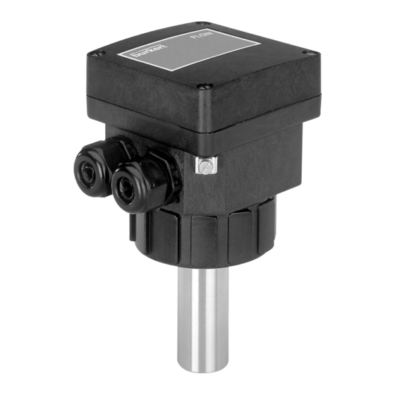
Burkert 8041 Instruction Manual
Insertion magmeter for high temperatures
Hide thumbs
Also See for 8041:
- Operating instructions manual (57 pages) ,
- Operating instructions manual (60 pages)

Related Manuals for Burkert 8041


Summary of Contents for Burkert 8041
- Page 1 INSERTION MAGMETER FOR HIGH TEMPERATURES Instruction Manual © Bürkert 2004 Subject to technical change without notice...
-
Page 2: Table Of Contents
Conformity with standards ..................33 Dimensions ........................34 Label description ......................34 ANNEX ........................35 Order codes ........................35 7.1.1 Finished products ........................... 35 7.1.2 Accessories and spare parts ......................35 Flow charts ........................36 Connection examples ....................38 8041... -
Page 3: Introduction
EN 100 015-1. Always protect the device from electromagnetic perturbations, and when installed outside, protect it from the rain and ultraviolet radiations. Manufacturer’s address Bürkert & Cie Rue du Giessen 67220 TRIEMBACH-au-VAL FRANCE 8041... -
Page 4: Description
CONVERSION OF THE FLOW VELOCITY INTO A FLOW RATE - FACTOR K The 8041 measures the flow velocity (in m/s) of the medium and converts it into a current (in mA) and a frequency rating (in Hz). The current I or the frequency f are proportional to the flow rate Q (l/s); The proportionality factor is called “factor K”:... - Page 5 INTRODUCTION Example Be a 8041 inserted into an S020, with DN50 and made of stainless steel: = 11,24 fitting The selected full scale is 5 m/s. The factor K to be used for the conversion of the output frequency f into a flow rate Q...
-
Page 6: Quick Start
This Quick Start diagram shows the different installation and programming steps to be carried out to ensure the good operation of the appliance. Unpack the appliance Contact your Order Burkert agent code OK? Unscrew the 4 screws ee 3.2 Select the mains frequency by means of switch 1 Select the filtering level by ee 3.3... - Page 7 3.6 Program the relay output ee 5.1, Error ee 3.1 signalling Check that the green led flashes once Replace the cover in the proper orientation (see photo) and screw the 4 screws The appliance is ready for use 8041...
-
Page 8: Configuration
CONFIGURATION GENERAL COMMENTS The 8041 magmeter has 2 operating modes: - the Readout mode: to visualize the measured flow velocity and the values programmed for the relay operation. - the Configuration mode: to calibrate the device (“zero flow” point and measuring full scale) and program the relay parameters. -
Page 9: Configuration Mode
* The device automatically goes back to the reading mode of the flow velocity measurement, if the push-button is not pressed for 10 s. Green led blinking Bargraph ..1 up to 5 times Led off Led lit Red led off Push-button Red led lit Led blinking 8041... - Page 10 CONFIGURATION 8041...
-
Page 11: Defining The Mains Frequency
50 Hz 60 Hz FILTERING LEVEL Filtering allows the attenuation of fluctuations in the flow. The 8041 sensor can work without or with filtering. Switch 2 makes it possible to activate or inhibit filtering : Flow filtering activation... -
Page 12: Zero Flow" Point Calibration
- Press and hold the push-button: after 2 seconds, the red led lights up (Configuration mode) and the bargraph shows the features “zero flow point 1 2 3 4 5 6 7 8 9 10 calibration” and “full scale calibration” alternately. Full scale calibration 8041... -
Page 13: Measuring Range Selection Or Full Scale Teach-In
0 to 5 m/s 0 to 10 m/s 0 to full scale (between 2 and 10 m/s) determined by teach-in When selecting a new measuring range, the percentages programmed for the low and high thresholds apply to the new selected full scale. 8041... -
Page 14: Full Scale Teach-In
The minimal value of the measuring range is 0 m/s. - Set both switches 4 and 5 to ON - Install the 8041 sensor into the pipe (see chapter Installation) - Let the max. flow flow through the pipe - Check whether the green led flashes once and the red led is off (Readout mode). -
Page 15: Programming The Relay Output
- The high switching threshold, in a percentage of the full scale - The time-out before switching, from 0 to 100 s. Whether the relay operating is Normally Open or Normally Closed is determined by the connection of the relay to the terminals of the electronic board. 8041... -
Page 16: Switching Mode Of The Relay Output
- Window mode: the change of state of the relay output (OUT) occurs at any threshold detection: Window mode (NO-wired realy) Window mode (NC-wired relay) Relay output Relay output Low threshold High threshold Low threshold High threshold 8041... - Page 17 Readout mode. or press and hold the push-button to display another feature. or wait for 10 s to return to the measured flow velocity Readout mode, without validating the displayed feature. 8041...
-
Page 18: Programming The Low Switching Threshold
0-10 m/s measuring the flow velocity Readout mode or wait for 10 s to range, this corresponds to a low return to the flow velocity Readout mode without threshold of 2.4 m/s validating the displayed value. 8041... -
Page 19: Programming The High Switching Threshold
Readout mode without 9th Led flashing twice = 2% of the validating the displayed value. full scale The bargraph shows 82% of the full scale, i.e. by a 0-10 m/s measuring range, this corresponds to a high threshold of 8.2 m/s 8041... -
Page 20: Programming The Time-Out Before Switching
Readout mode or wait for 10 s to return to the flow velocity Readout mode without 5 leds lit = 50 sec 6th led flashing 2 times = 2 seconds validating the displayed value. The bargraph shows a time-out of 52 seconds 8041... -
Page 21: Installation
- Dismounting precautions: All precautions must be taken before removing the transmitter from the pipe depending on the process used as the pipe may contain dangerous/agressive hot fluids or fluids with high temperatures or pressures. 8041... -
Page 22: Mounting Positions
It is advisable to mount the transmitter at a 45° angle to the 45° horizontal centre of the pipe as shown in the diagram to avoid having deposits on the electrodes and false measurements due to air bubbles. 45° 8041... - Page 23 3 x DN 10 x DN Please ensure the pipe design does not allow the build up of air bubbles or cavities within the medium as this will cause measuring errors. Flow direction Flow direction Correct Incorrect Correct Incorrect 8041...
-
Page 24: Installation
- Use cables with a temperature limit of 105°C minimum. - For normal operating conditions the measuring signal can be transmitted by a shielded cable of 0.75 mm cross section. - The cable must not be installed in combination with carrying lines with a higher voltage or frequency. 8041... - Page 25 18-36VDC (**) Metallic devices (valve, pump,...) or plastic pipe applications or metallic parts, inserted inside the pipe. (**) If direct earthing is impossible, connect a 100 nF/50 V-condensator between the negative terminal of the power supply and the earth. 8041...
-
Page 26: Electrical Wiring
Unscrew the cable gland nut, insert the obstructor and screw the nut back onto the cable gland. Always replace the cover as indicated by the photo opposite ; Screw the 4 screws in an alternating pattern. 8041... -
Page 27: Connection Of The 4-20 Ma Current Output
1 2 3 4 5 6 sinking mode 4...20 V+ V- PE Pls+Pls- Connection in sinking mode If direct earthing is impossible, connect a 100 nF/50 V-condensator between the negative terminal of the power supply and the earth. 8041... -
Page 28: Connection Of The Frequency Output
INPUT 1 2 3 4 5 6 1 2 3 4 5 6 4...20 V+ V- PE Pls+Pls- 4...20 V+ V- PE Pls+Pls- 8041 8041 Connection to a PLC Connection to a PLC with common - (PNP) with common + (NPN) -
Page 29: Connection Of The Relay Output
INSTALLATION 4.4.3 Connection of the relay output The relay output can operate either in a Normally Open or Normally Closed configuration depending on the wiring to the 8041 electronic board. 18-36 V= Power Supply Normally Open Connection of the relay... -
Page 30: Maintenance
MAINTENANCE ERROR SIGNALLING An error is indicated by special flashing of the red led. 8041... -
Page 31: Cleaning
MAINTENANCE CLEANING The 8041 sensor may be cleaned with water or a product which is compatible with the materials therein.Your Burkert supplier is available to provide you with any additional information you require. 8041... -
Page 32: Technical Data
Duty cycle = 50% +/-1% - Max current 100 mA (protected against short-circuits and polarity reversals) Current output - Output type Current output from 4 to 20 mA (22 mA for error signalling) - Electrical wiring sourcing or sinking mode 8041... -
Page 33: Safety
Fluids of group 2 according to §1.3b of the directive: PN ≤ 16 bar and DN ≤ 200 It has been designed and manufactured professionally (Article 3.3). The CE mark is not for pressure. The CE mark complies with directives 89/336/EC (EMC) and 73/23/EC (LVD). 8041... -
Page 34: Dimensions
SPECIFICATIONS DIMENSIONS 115 mm 88 mm M20 x 1.5 LABEL DESCRIPTION FLOW:8041-EPDM -IND LONG SST N=10000 18-36V — /220mA 4-20mA REL:230VAC/3A Compact 552780 W41UE Type of magmeter Gasket material Sensor characteristics Serial number Version of the magmeter Relay data Manufacturer code... -
Page 35: Annex
7.1.1 Finished products - 552779: 8041 with 1 short stainless steel sensor, 1 current output, 1 frequency output, 1 relay output, 2 M20 x 1.5 mm cable glands + 1 set including 1 cable gland obturator, 1 cable gland 2x6 mm... -
Page 36: Flow Charts
DN 06 0.05 0.05 0.01 0.005 0.02 0.01 0.3 0.5 Flow velocity Selection example: Nominal flow rate = 10 m Ideal flow velocity = 2-3 m/s => As defined by the flow chart the required fitting diameter is DN40. 8041... - Page 37 1/2'' DN15 1/4'' DN08 1/4'' DN06 0.05 0.02 0.01 0.3 0.5 Flow velocity Selection example: Nominal flow rate = 50 gpm Ideal flow velocity = 8 fps => As defined by the flow chart the required fitting diameter is 1’’1/2. 8041...
-
Page 38: Connection Examples
ANNEX CONNECTION EXAMPLES Between the 8041 magmeter and the flow transmitter 8025, Low Flow or Batch, in a panel version. On a panel version of the 8025 Low Flow, set SW100 to position 1 and SW101 to position 3. 18-30 V=... - Page 39 ANNEX Between the 8041 magmeter and the positioner 1067 mounted on a diaphragm valve 2031 24 V= 24 VDC +24 V 4-20 mA I/O4 I/O3 1 2 3 4 5 6 I/O2 I/O1 4...20 V+ V- PE Pls+ Pls- 1067...
- Page 40 ANNEX 8041...
Need help?
Do you have a question about the 8041 and is the answer not in the manual?
Questions and answers