Burkert 8098 Operating Instructions Manual
Flowave
saw flowmeter
software version a.02.00.00 and higher
Hide thumbs
Also See for 8098:
- Quick start manual (68 pages) ,
- Operating instructions manual (354 pages) ,
- Quick start manual (52 pages)

Related Manuals for Burkert 8098


Summary of Contents for Burkert 8098
- Page 1 Type 8098 FLOWave SAW Flowmeter Operating Instructions Software version A.02.00.00 and higher...
- Page 2 We reserve the right to make technical changes without notice. © Bürkert SAS, 2015 - 2018 Operating Instructions 1809/03_EU-EN 00567647 / Original EN...
- Page 3 Type 8098 Generalcontents General information...................................5 Description.........................................11 technical Data......................................19 installation in the pipe...................................33 electrical installation..................................45 DoinG the settinGs....................................67 menu Display ......................................85 General.settinGs ..................................93 menu saW.sensor paraMeter ............................. 131 menu menu saW.sensor DiaGnostiCs ............................193 saW.sensor...
- Page 4 Type 8098 Generalcontents English...
-
Page 5: Table Of Contents
Type 8098 General information about.these.operatinG.instruCtions........................6 symbols.used...................................6 1.1. Definition.of.the.word.device............................6 1.2. 1.3. Definition.of.the.word.büs..............................7 1.4. Validity.of.the.operating.instructions..........................7 intenDeD.use.....................................7 basiC.safety.inforMation..............................8 General.inforMation................................10 4.1. Manufacturer's.address.and.international.contacts..................10 4.2. Warranty.conditions................................10 4.3. information.on.the.internet.............................10 English... -
Page 6: About.these.operating.instructions
Indicates a procedure to be carried out. highlighted.term is related to a menu or a menu item. Indicates the result of a specific instruction. Definition of the term device The term "device" used in these Operating Instructions always refers to the Type 8098 flowmeter. English... -
Page 7: Definition.of.the.word.büs
Type 8098 AbouttheseOperatingInstructions Definition of the term büs The term "büS" used in these Operating Instructions refers to the industrial communication, developed by Bürkert, based on the CANopen protocol. → For more information on büS, read the cabling guide available in English and German (Cabling_guide_for_ büS_networks.pdf) at www.buerkert.com search for "Guide for planning büS networks". -
Page 8: Basic.safety.information
Type 8098 Basicsafetyinformation bAsic sAfeTy informATion This safety information does not take into account any contingencies or occurrences that may arise during instal- lation, use and maintenance of the product. The operating company is responsible for the respect of the local safety regulations, including staff safety. - Page 9 Type 8098 Basicsafetyinformation caution risk.of.injury.due.to.a.heavy.device. A heavy device can fall down during transport or during installation and cause injuries. ▶ Transport, install and dismantle a heavy device with the help of another person. ▶ Use appropriate tools. notice the.device.may.be.damaged.by.the.measured.fluid. ▶ Systematically check the chemical compatibility of the component materials of the device and the fluids likely...
-
Page 10: General.information
The condition governing the legal warranty is the conforming use of the device in observance of the operating conditions specified in the Operating Instructions. information on the internet You can find the operating instructions and the technical data sheets for Type 8098 at: www.burkert.com English... - Page 11 Type 8098 Description DesCription.....................................12 5.1. Knowing.the.device................................12 5.1.1 Wi-Fi module ............................13 5.1.2 Unlocking magnetic key ........................14 5.2. understanding.the.rating.plates..........................14 5.3. Marking.with.the.MaC.address............................16 5.4. Description.of.the.device.status.leD........................17 English...
-
Page 12: Description
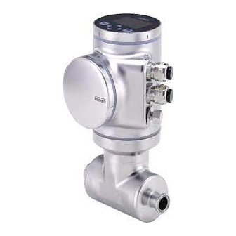
DescripTion Knowing the device The Type 8098 flowmeter is made up of a Type SE98 transmitter and a Type S097 flow sensor. The following pictures describe the main versions of the Type 8098 flowmeter: • Fig. 1 describes a device with 2 M20x1,5 cable glands in stainless steel (or in nickel plated brass) and 1 5-pin M12 male connector. -
Page 13: Wi-Fi Module
Type 8098 Description Blind cover or display module (Type ME31) Device status LED indicating the status of the device, and seal Transmitter housing, including the electronic modules Type SE98 transmitter Seal 4-pin M12 female connectors with plugs 5-pin M12 male connector, with... -
Page 14: Unlocking Magnetic Key
• 1 analogue output, • 1 digital output, • 1 output, which can be configured as an analogue output or as a digital output. understanding the rating plates 8098 FLOWave Flowmeter Supply: 12-35 5W Max. IP65 / IP67 Temp. ambient: -10 to 70°C... - Page 15 Type 8098 Description 8098 FLOWave Flowmeter IP65 / IP67 / NEMA 4X Temp. ambient: -10 to 55°C 88888888 SN 999999 CAN_H CAN_L CAN shield W49MN Made in France 28-04 1. Protection class of the device 7. Conformity marking 2. Type of the device 8.
-
Page 16: Marking.with.the.mac.address
Type 8098 Description S097 FLOWave Flow sensor Pipe: 316L/1.4435 Housing: 304/1.4301 DIN 11866 C / Clamp D50.5 DIN 32676 B DN15 PN25bar Max. flow:10 m3/h Temp. medium : -20 to 110°C W4ZMN Made in France 1. Type of the flow sensor 2. -
Page 17: Description.of.the.device.status.led
Type 8098 Description Description of the device status leD Ex works, the LED that indicates the state of the device changes its colour and state based on the NAMUR NE 107 recommendation. If several states exist simultaneously, the state with the highest priority is displayed. The priority is determined by the severity of the deviation from standard operation (red LED = failure, error or malfunction = highest priority). - Page 18 Type 8098 English...
- Page 19 Type 8098 Technical data teChniCal.Data....................................20 6.1. operating.conditions.................................20 6.2. Conformity.to.standards.and.directives........................20 6.3. Conformity.to.the.pressure.equipment.Directive....................20 6.4. ul.certification..................................21 6.5. eheDG.certification................................21 6.6. fluid.data....................................22 6.7. Measurement.data................................24 electrical.data..................................25 6.8. Mechanical.data..................................26 6.9. 6.10. specifications.of.the.ethernet.industrial.communication................28 6.10.1 Modbus TCP protocol ........................28 6.10.2...
-
Page 20: Technical Data
Type 8098 Technicaldata TechnicAl DATA operating conditions Ambient temperature • Device with 2 M20x1,5 cable • –10...+70 °C glands and 1 5-pin M12 connector • Device with 2 4-pin M12 female • –10...+55 °C connectors and 1 5-pin M12 con-... -
Page 21: Ul.certification
Type 8098 Technicaldata type.of.fluid. Conditions. DN ≤ 200 Fluid group 2, Article 4, Paragraph 1.c.ii or PS ≤ 10 or PSxDN ≤ 5000 ul certification The devices with variable key PU01 or PU02 are UL-certified devices and comply also with the following standards: • UL 61010-1 •... -
Page 22: Fluid.data
Type 8098 Technicaldata fluid data Ambient temperature °C Temperatures authorized for a limited duration °C Fluid temperature Fig. 8: Dependency between the fluid temperature and the ambient temperature, device with 2 M20x1,5 cable glands and 1 5-pin M12 male connector Ambient temperature °C Temperatures authorized for a limited duration °C Fluid temperature Fig. 9: Dependency between the fluid temperature and the ambient temperature, device with 2 4-pin M12 female connectors and 1 5-pin M12 male connector (Ethernet version) Fluid temperature –20...+110 °C, with clamp process connections. Up to 140 °C for maximum 60 minutes for a sterilisation process. - Page 23 Type 8098 Technicaldata size.of.the.process. standards.the.process.connections. type.of.process.connection connection conform.to • DIN 11864-3 series A • DIN 11864-3 series B clamp PN25 • DIN 32676 series A DN15, DN25 • DIN 32676 series B • DIN 11864-2 series A flange PN25 • DIN 11864-2 series B...
-
Page 24: Measurement.data
Type 8098 Technicaldata measurement data Flow rate measurement • Measurement range • 0...7 m /h to 0...90 m /h, depending on the DN of the sensor • Measurement deviation for a flow rate • ±0.4% of the measured value 1) 2) -
Page 25: Electrical.data
Type 8098 Technicaldata electrical data Voltage not allowed Ambient temperature °C Temperature authorized for a limited duration Supply voltage V DC Fluid temperature °C Fig. 10: Minimum supply voltage depending on the ambient temperature and the fluid temperature, device with 2 M20x1,5 cable glands and 1 5-pin M12 male connector Voltage not allowed Ambient temperature °C Temperature authorized for a limited duration Supply voltage V DC Fluid temperature °C... -
Page 26: Mechanical.data
• Galvanically isolated, passive • Overload information through diagnostics software function • Protected against overloads • Protected against polarity reversals mechanical data Dimensions and weight of the device: refer to the technical data sheet regarding Type 8098 available at www.buerkert.com Table 3: Materials in contact with ambient air Component... - Page 27 Type 8098 Technicaldata Component Material Stainless steel / Stainless steel 5-pin M12 male connector / Screwed plug (depending on the version of the device) Nickel plated brass / Nickel plated brass 4-pin M12 female connector / Blind plug Stainless steel / Stainless steel...
-
Page 28: Specifications.of.the.ethernet.industrial.communication
Type 8098 Technicaldata 6.10 specifications of the ethernet industrial communication Table 6: Specifications of the industrial communication module Network speed 10/100 mbps Auto negotiation Auto MDI/MDI-X Switch function Network diagnostics Yes, via error telegram Individual identification number, stored in the module MAC-ID and on the outside of the device (see rating plate) -
Page 29: Ethernet/Ip Protocol
Type 8098 Technicaldata Network topology • Tree • Star • Ring (closed daisy chain) • Line (open daisy chain) Network management • LLDP (Link Layer Discovery Protocol) • SNMP V1 (Simple Network Management Protocol) • MIB-II (Management Information Base) • Physical device Additional supported features •... - Page 30 Input (Consumer to Producer or Adapter to Scanner) • All diagnostics and errors information has the highest priority and can be read by a PLC (refer to the con- cerned protocol file available at www.burkert.com). • PDO: value, status, unit • Device and modules: status •...
-
Page 31: Ethercat Protocol
Type 8098 Technicaldata 6.10.4 ethercAT protocol Industrial Ethernet interface X1, X2 • X1: EtherCAT IN • X2: EtherCAT OUT Maximum number of cyclic input and output data 512 bytes in total Maximum number of 1024 bytes cyclic input data Maximum number of... - Page 32 Type 8098 English...
- Page 33 Type 8098 installation in the pipe installation.in.the.pipe................................34 safety.instructions................................34 7.1. preparing.the.device.before.installation.into.the.pipe..................35 7.2. 7.2.1 Changing the position of the transmitter on the sensor ............35 7.2.2 Switching positions of the blind cover and the display module ..........39 recommendations.for.the.installation.into.the.pipe..................41 7.3. installing.the.device.into.the.pipe..........................44 7.4.
-
Page 34: Installation In The Pipe
Type 8098 Installationinthepipe insTAllATion in The pipe safety instructions DanGer risk.of.injury.due.to.electrical.voltage.. ▶ Before carrying out work on the system, disconnect the electrical power for all the conductors and isolate it. ▶ Observe all applicable accident protection and safety regulations for electrical equipment. -
Page 35: Preparing.the.device.before.installation.into.the.pipe
Type 8098 Installationinthepipe WarninG risk.of.injury.if.the.fluid.pressure/temperature.dependency.is.not.respected. ▶ Observe the fluid temperature-pressure dependency. Refer to chpt. 6.6 Fluid data. ▶ Observe Pressure Equipment Directive 2014/68/EU. caution risk.of.injury.due.to.a.heavy.device. A heavy device can fall down during transport or during installation and cause injuries. ▶ Transport, install and dismantle a heavy device with the help of another person. - Page 36 Type 8098 Installationinthepipe → To change the position of the transmitter as it is described in chpt. 5.1, do the following: For safety reasons and to comply with standard UL 61010-1, the blind cover and the display module are locked.
- Page 37 Type 8098 Installationinthepipe 6. Use a size 3 hexagonal key to loosen the screw that is marked with the arrow and that locks the trans- mitter to the flow sensor. 7. Hold the flow sensor with one hand and, with the other hand, turn the transmitter by about 20 degrees counterclockwise.
- Page 38 Type 8098 Installationinthepipe 11. Turn the transmitter to the desired position. Fold the cable in a Z-shape and make sure the cable stays inside the transmitter. 13. Turn the transmitter by about 20 degrees counterclockwise. 14. Screw the transmitter clockwise on the flow sensor until the blind cover is perfectly parallel or perpen- dicular to the axis of the pipe.
-
Page 39: Switching Positions Of The Blind Cover And The Display Module
Type 8098 Installationinthepipe 16. Connect the display module to the transmitter. 17. Put the mark of the cover on the unlocked marking of the housing and screw the cover clockwise on the transmitter until the mark is on the locked position. - Page 40 Type 8098 Installationinthepipe 3. Carefully lift the display module because a cable connects the display module to the transmitter. 4. Push the tab of the cable connector to disconnect the display module from the transmitter. 5. Remove the display module and put it on a clean surface to protect the seal from dirt.
-
Page 41: Recommendations.for.the.installation.into.the.pipe
Type 8098 Installationinthepipe 11. Put the mark of the blind cover on the unlocked marking of the top of the transmitter housing. 12. Screw the blind cover clockwise on the transmitter until the mark is on the locked position. You should hear a click. - Page 42 Type 8098 Installationinthepipe → To allow proper self-draining and to respect the 3A and EHEDG requirements, install the device into a pipe with a minimum angle against the horizontal. See Table 7. Table 7: Minimum angle against the horizontal for proper self-draining angle.against.the. type.of.process.connection standards.the.process.connections.conform.to horizontal • DIN 32676 series A •...
- Page 43 Type 8098 Installationinthepipe → To make sure the internal temperature of the transmitter with cable glands does not exceed the authorized maximum value, install the device as recommended in Fig. 15. → To make sure the internal temperature of the transmitter does not exceed the authorized maximum value, install an Ethernet version of the device as recommended in Fig.
-
Page 44: Installing.the.device.into.the.pipe
Type 8098 Installationinthepipe installing the device into the pipe caution risk.of.injury.due.to.a.heavy.device. A heavy device can fall down during transport or during installation and cause injuries. ▶ Transport, install and dismantle a heavy device with the help of another person. ▶ Use appropriate tools. - Page 45 Type 8098 electrical installation eleCtriCal.installation...............................46 safety.instructions................................46 8.1. specifications.of.the.cable.for.the.5-pin.M12.male.connector..............48 8.2. assembling.and.wiring.the.5-pin.M12.female.connector.(a-coding)............48 8.3. Connecting.the.device.to.a.power.supply......................49 8.4. Connecting.the.device.to.a.büs./.Canopen.network..................50 8.5. activating.the.device.internal.termination.resistor.(only.büs.network)..........51 8.6. specifications.of.the.cables.for.the.M20x1,5.cable.glands.(only.device.with.cable.glands)..51 8.7. specifications.of.the.conductors.for.the.12.push-in.terminal.strip............52 8.8. 8.9. terminal.assignment.of.the.12.push-in.terminal.strip..................52 8.10. opening.the.front.of.the.transmitter.........................53 8.11. Wiring.the.device.through.the.M20x1,5.cable.glands.in.stainless.steel.(only.device.with.cable.
-
Page 46: Electrical Installation
Type 8098 Electricalinstallation elecTricAl insTAllATion safety instructions DanGer risk.of.injury.due.to.electrical.voltage.. ▶ Before carrying out work on the system, disconnect the electrical power for all the conductors and isolate it. ▶ Observe all applicable accident protection and safety regulations for electrical equipment. - Page 47 Type 8098 Electricalinstallation WarninG risk.of.injury.due.to.unintentional.switch.on.of.the.power.supply.or.uncontrolled.restart.of.the. installation. ▶ Take appropriate measures to avoid unintentional activation of the installation. ▶ Guarantee a set or controlled process restart after carrying out any device intervention. caution risk.of.injury.due.to.a.heavy.device. A heavy device can fall down during transport or during installation and cause injuries.
-
Page 48: Specifications.of.the.cable.for.the.5-Pin.m12.Male.connector
Type 8098 Electricalinstallation specifications of the cable for the 5-pin m12 male connector Use a 5-pin M12 female connector (not supplied) to connect the 5-pin M12 male connector, for example the M12 female connector with article number 917116. If you use the M12 female connector with article number 917116, observe the specifications for the cable and conductors, given in Table 8. -
Page 49: Connecting.the.device.to.a.power.supply
Type 8098 Electricalinstallation connecting the device to a power supply The device is wired in the factory to be easily energized through the 5-pin M12 male connector. → Connect the device with 2 4-pin M12 female connectors (Ethernet version) to a 12...35 V DC power supply through the 5-pin M12 male connector;... -
Page 50: Connecting.the.device.to.a.büs./.Canopen.network
Type 8098 Electricalinstallation connecting the device to a büs / cAnopen network The 5-pin M12 male connector (A-coding) is used to connect the device: • To a 12...35 V DC power supply and/or • To the büS / CANopen network. -
Page 51: Activating.the.device.internal.termination.resistor.(Only.büs.network)
Type 8098 Electricalinstallation Activating the device internal termination resistor (only büs network) The device has an internal termination resistor that can be activated if the device is installed at one end of büS. If you activate the device internal termination resistor, do not install a termination resistor at the same end of büS. -
Page 52: Specifications.of.the.conductors.for.the.12.Push-In.terminal.strip
Type 8098 Electricalinstallation specifications of the conductors for the 12 push-in terminal strip Table 11: Specifications of the conductors for the terminal strip specification.of.the.conductors recommended.value.range Cross section of a solid conductor H05(07) V-U 0,25...1,5 mm Cross section of a stranded conductor H05(07) V-K, 0,25...1,5 mm with a wire ferrule but without collar Cross section of a stranded conductor H05(07) V-K, 0,25...0,75 mm... -
Page 53: Opening.the.front.of.the.transmitter
Type 8098 Electricalinstallation Fig. 23: Wiring ex works of the 12 push-in terminal strip → If you need to disconnect a conductor, first push the terminal with a slot screwdriver 3.0 mm (any length) and a force of max. 40 N. 8.10 opening the front of the transmitter To open the front of the transmitter housing, remove either the blind cover or the display module. - Page 54 Type 8098 Electricalinstallation procedure.to.open.the.front.of.the.transmitter..if.the.display.module.is.on.the.front.of.the.device 1. Remove the blind cover from the top of the transmitter. 2. Put the magnetic key on the mark related to the display module. You should hear a click indi- cating that the display module is unlocked. Do not use a tool to turn the display module.
-
Page 55: Wiring.the.device.through.the.m20X1,5.Cable.glands.in.stainless.steel
Type 8098 Electricalinstallation 8.11 Wiring the device through the m20x1,5 cable glands in stainless steel (only device with cable glands) Put only one cable in each cable gland. → Prepare cables that obey the specifications given in chpt. 8.7 and chpt. 8.8. - Page 56 Type 8098 Electricalinstallation 11. Put the functional earth plate in its original place. Functional earth 12. Use a size 10 hexagonal key to tighten the 2 screws of the functional earth plate to a torque of 0.2 N·m (0.15 ft·lbf).
-
Page 57: Wiring.the.device.through.the.m20X1,5.Cable.glands.in.nickel.plated.brass
Type 8098 Electricalinstallation 8.12 Wiring the device through the m20x1,5 cable glands in nickel plated brass (only device with cable glands) Put only one cable in each cable gland. → Prepare cables that obey the specifications given in chpt. 8.7 and chpt. 8.8. - Page 58 Type 8098 Electricalinstallation 9. Attach each cable to the functional earth plate. The shield must be in contact with the functional earth plate. 10. Put the functional earth plate in its original place. Functional earth 11. With an hexagonal key size 10, tighten the 2 screws of the functional earth plate to a torque of 0.2 N·m...
-
Page 59: Connecting.the.functional.earth.(Device.with.2.M20X1,5.Cable.glands)
Type 8098 Electricalinstallation 8.13 connecting the functional earth (device with 2 m20x1,5 cable glands) → For a proper function of device always connect the yellow/green functional earth conductor: - either to the functional earth plate in the transmitter housing (see Fig. 29 in chpt. 8.14), - or to the functional earth screw on the outer surface of the transmitter housing (see Fig. -
Page 60: Connecting.the.device.to.a.12
Type 8098 Electricalinstallation 8.14 connecting the device to a 12...35 V Dc power supply through the m20x1,5 cable glands (only device with cable glands) 1. Use a 3.0 mm slot screwdriver (any length) and a force of max. 40 N to push the terminal 5 and disconnect the white conductor. - Page 61 Type 8098 Electricalinstallation Fig. 30: Device connected to a 12...35 V DC power supply through the M20x1,5 cable glands 8.15 Wiring output 1 (analogue) and output 3 configured as an analogue output (only device with cable glands) notice risk.of.short-circuit.if.the.configuration.of.output.3.is.wrong. ▶ Before wiring output 3 as an analogue output, make sure output 3 is configured as an analogue output in the Parameter menu of the outputs.
-
Page 62: Wiring.output.2.(Digital).And.output.3.Configured.as.a.digital.output
Type 8098 Electricalinstallation 8.16 Wiring output 2 (digital) and output 3 configured as a digital output (only device with cable glands) notice risk.of.short-circuit.if.the.configuration.of.output.3.is.wrong. ▶ Before wiring output 3 as an analogue output, make sure output 3 is configured as an analogue output in the Parameter menu of the outputs. -
Page 63: Knowing.the.status.of.the.ethernet.network
Type 8098 Electricalinstallation 8.17 Knowing the status of the ethernet network (only device with 2 4-pin m12 female connectors - ethernet version) The status of the Ethernet network is indicated by LEDs. The LEDs are located on the industrial communication module in the transmitter housing. -
Page 64: Specifications.of.the.cables.and.conductors.for.the.4-Pin.m12.Female.connectors
Type 8098 Electricalinstallation 8.18 specifications of the cables and conductors for the 4-pin m12 female connectors Table 14: Specifications of the cables and conductors for the 4-pin M12 female connectors specification.of.the.cables.and.conductors recommended.value Electromagnetic protection (EMC) Shielded conductor with minimum STP Minimum category CAT-5 Maximum length 100 m Maximum operating temperature min. 90 °C 8.19... -
Page 65: Connecting.the.functional.earth
Type 8098 Electricalinstallation Cable and conductors connected inside the device from X1 to the upper 4-pin M12 female connector Cable and conductors connected inside the device from X2 to the middle 4-pin M12 female connector Cable and conductors connected inside... - Page 66 Type 8098 English...
- Page 67 Type 8098 Doing the settings hoW.to.Do.the.settinGs..............................68 safety.instructions................................68 9.1. available.software.to.do.the.settings........................68 9.2. 9.3. preparing.the.bürkert.Communicator.software....................68 9.4. Display.module:.description.of.the.user.interface.....................70 9.4.1 Description of the display .........................71 9.4.2 How to use the touch sensitive keys .....................72 9.4.3 Minimum and maximum values when entering a numerical value ...........72 available.login.user.levels..............................72...
-
Page 68: How.to.do.the.settings
Type 8098 Howtodothesettings hoW To Do The seTTinGs safety instructions WarninG risk.of.injury.due.to.non-conforming.adjustment. Non-conforming adjustment could lead to injury and damage the device and its surroundings. ▶ The operators in charge of adjustment must have read and understood the contents of the Operating Instructions. - Page 69 Type 8098 Howtodothesettings 7. Insert the appropriate power adapter into the AC/DC adapter. 8. Connect the cable of the AC/DC adapter to the related connector of the female M12 connector. Termination Female M12 resistance connector büS stick Power adapter Y plug...
-
Page 70: Display.module:.description.of.the.user.interface
Type 8098 Howtodothesettings Display module: description of the user interface To get detailed information on the display software, refer to the Operating Instructions of the Type ME31 display software, available on the internet at www.burkert.com The user interface is made up of a display and touch sensitive keys. -
Page 71: Description Of The Display
Type 8098 Howtodothesettings 9.4.1 Description of the display Symbol of the active user level. See chpt. 9.5 Available login user levels. Symbol of the device status Information bar Display parameter To the DIAG- Brightness NOSTICS menu, by Contrast pressing Screen saver... -
Page 72: How To Use The Touch Sensitive Keys
Type 8098 Howtodothesettings 9.4.2 how to use the touch sensitive keys highlighted.terms are related to menus or menu items. Table 15: How to use the keys Description Short press: to go back to the parent menu or to the parent view. This key is called BACK in the display messages. -
Page 73: Default.settings
Refer to the related Operating Instructions. Default settings You can find the default settings of the device in the CANopen supplement for the Type 8098 at www.burkert. → Before making any changes to the settings, use the Bürkert Communicator software to print a pdf file with all the default settings of the device. -
Page 74: Menu.structure
Type 8098 Howtodothesettings menu structure View 1 of 4 CONFIGURATION Volume.flow 30.1 SAW sensor To navigate through the list of l/min available menu items Configuration view First view, displayed after energizing the device, that can be changed by the user... -
Page 75: Opening Or Closing The Context Menu In Any View (Display Module Only)
Type 8098 Howtodothesettings 9.7.1 opening or closing the context menu in any view (display module only) The user can open a context menu in any view. The content depends on the active view. To open the context menu: → Press and hold The context menu is open. -
Page 76: Adding Your Own Context Menu Items (Shortcuts, Display Module Only)
Type 8098 Howtodothesettings View Menu.items.of.the.context.menu Messages.overview To display the list of messages generated by the device. save To save the changes. To display the access path to the displayed menu item. Not Where.am.i? available in the wizard. in a menu add.shortcut... -
Page 77: Reading Out The Messages Generated By The Device
→ To read out the messages in the Bürkert Communicator software, refer to the Operating Instructions Type 8920, available on the internet at www.burkert.com Do the following to display the generated messages on the display module: →... -
Page 78: Changing The Login User Level If The Adjustment Is Protected Through Passwords
• you are automatically logged out after the activation delay of the screen saver has elapsed. → To log out from the active user level in the Bürkert Communicator software, refer to the Operating Instructions Type 8920, available on the internet at www.burkert.com Do the following to log out from the advanced.user, the installer bürkert... -
Page 79: Reading Out The Access Path To A Menu Item (Display Module Only)
Type 8098 Howtodothesettings 9.7.7 reading out the access path to a menu item (display module only) If you are lost in the menu structure, you can display the access path. → Long press, to open the context menu. → Where.am.i? Confirm. -
Page 80: Navigating In A Wizard And Adjusting Numbers
Type 8098 Howtodothesettings 9.8.2 navigating in a wizard and adjusting numbers General settings parameter Quick start Diagnostics Date and time Language English Confirm Parameter Current date/time 1/9 Current date:08/24/15 Current time:08:57:16 Daylight savings Current time zone:+00:London Go back to the previous screen (available at each step of the wizard) Confirm to go to the next screen. -
Page 81: Setting Negative Or Positive Numbers
Type 8098 Howtodothesettings 9.8.3 setting negative or positive numbers Settings Error low max: 150.00 -020.000 min: -20.00 To set a positive number: → to increase the number until the positive value is reached. Settings Error low max: 150.00 010.000 min: -20.00 To set a negative number: →... -
Page 82: Entering A Name
Type 8098 Howtodothesettings 9.8.4 entering a name SAW sensor parameter stand..meas..values. [ +] Add. meas. values [+] Diag. events Refresh time Long Confirm SAW sensor stand..meas..values Volume flow Temperature Liquid velocity Totalizer 1 Confirm SAW sensor Volume.flow Value name Volume flow Damping ... -
Page 83: Activating Or Deactivating A Feature
Type 8098 Howtodothesettings 9.8.5 Activating or deactivating a feature General settings parameter Date and Time Language English Passwords Physical units Confirm Parameter passwords Password protection Confirm Passwords password.protection Deactivate / Activate Save Fig. 46: Activating or deactivating a feature English... - Page 84 Type 8098 English...
- Page 85 Type 8098 Display menu Display.MoDule.settinGs..............................86 10.1. safety.instructions................................86 10.2. Doing.the.Quick.start.adjustments.when.energizing.the.device.for.the.first.time.(display. module.only)...................................86 10.3. Menu.parameter...................................87 10.3.1 Adjusting the brightness of the display backlight ...............87 10.3.2 Adjusting the contrast of the display (chapter has been moved here) ........87 10.3.3 Adjusting the activation delay of the screen saver ..............88 10.3.4...
-
Page 86: Display.module.settings
Type 8098 Displaymodulesettings DisplAy moDule seTTinGs The section describes the menus related to the display module which is fitted on the device. 10.1 safety instructions WarninG risk.of.injury.due.to.non-conforming.adjustment. Non-conforming adjustment could lead to injury and damage the device and its surroundings. -
Page 87: Menu.parameter
Type 8098 Displaymodulesettings → Choose the unit system for all the measurements Confirm. → Save the Quick.start settings or go back to the parent menu without saving the new settings. 10.3 menu parameter 10.3.1 Adjusting the brightness of the display backlight the.brightness.of.the.display.is.automatically.reduced.if.the.internal.device.temperature.is.higher. -
Page 88: Adjusting The Activation Delay Of The Screen Saver
Type 8098 Displaymodulesettings → Save. The contrast of the display is adjusted. 10.3.3 Adjusting the activation delay of the screen saver The screen saver allows you to: • Save energy. • Automatically go back to View 1. • And, if the adjustment is protected through passwords, to be automatically logged out from an advanced.user,... -
Page 89: Unlocking The Screen Saver
Type 8098 Displaymodulesettings 10.3.5 unlocking the screen saver To unlock the display when the screen saver is active, do the following to have access to any view again: → Press any key twice. The first key of the unlock sequence is displayed. -
Page 90: Menu.diagnostics
Type 8098 Displaymodulesettings 10.4 menu Diagnostics 10.4.1 reading out the temperature of the display module To read out the temperature of the display module, do the following: → ConfiGuration Go to the view. → Display → parameter Confirm to access the view. -
Page 91: Reading Out The Article Number Of The Display Module
Type 8098 Displaymodulesettings → parameter Confirm to access the view. → Go to the MaintenanCe view. → Version.numbers → hardware.version The version number of the hardware of the display module is displayed. → Go back to the parent menu. 10.5.3... -
Page 92: Reading Out The Serial Number Of The Display Module
Type 8098 Displaymodulesettings 10.5.5 reading out the serial number of the display module To read out the serial number of the display module, do the following: → Go to the ConfiGuration view. → Display → Confirm to access the parameter view. - Page 93 Type 8098 General.settings menu General.settinGs.-.paraMeter............................96 11.1. safety.instructions................................96 11.2. user.levels.of.the.editable.menu.items........................96 11.3. Default.settings..................................96 11.4. Changing.the.operating.mode.of.the.device.status.leD.or.switching.off.the.status.leD..97 11.4.1 Changing the operating mode of the device status LED ............97 11.4.2 Switching off the status LED ......................97 11.5. setting.the.basic.parameters.for.identifying.the.device.on.büs...............98 11.5.1...
- Page 94 Type 8098 11.13.Changing.the.date.and.the.time..........................110 11.14.Changing.the.display.language..........................111 11.15.activating.the.adjustment.protection.through.passwords................. 111 11.16.Changing.the.protection.passwords.of.the.advanced.user.and.installer.user.levels....112 11.17.Deactivating.the.adjustment.protection.through.passwords..............112 11.18.Changing.the.units.of.the.physical.quantities....................113 General.settinGs.-.DiaGnostiCs..........................114 12.1. user.levels.of.the.menu.items..........................114 12.2. reading.out.data.related.to.the.device......................... 114 12.2.1 Reading out the number of operating hours of the device ............ 114 12.2.2...
- Page 95 Type 8098 12.4.4 Reading out the number of managed modules ................ 122 12.4.5 Reading out the number of missing modules ................123 12.4.6 Reading out the number of failed configuration loads ............123 12.4.7 Reading out the number of failed reconfigurations ..............124 12.4.8...
-
Page 96: General.settings.-.Parameter
11.3 Default settings You can find the default settings of the device in the CANopen supplement for the Type 8098 at www.burkert.com → Before making any changes to the settings, use the Bürkert Communicator software to print a pdf file with all the default settings of the device. -
Page 97: Changing.the.operating.mode.of.the.device.status.led.or.switching.off.the.status.led
Type 8098 Generalsettings-Parameter 11.4 changing the operating mode of the device status leD or switching off the status leD By default, the LED gives information on the device state, according to the NAMUR NE 107 standard (naMur. mode). The following other operating modes of the device status LED are available: •... -
Page 98: Setting.the.basic.parameters.for.identifying.the.device.on.büs
Type 8098 Generalsettings-Parameter 11.5 setting the basic parameters for identifying the device on büs The Displayed.name, the location and the Description allow you to clearly identify the device on büS. 11.5.1 entering a name for the device The entered name will be shown on any display (e.g. the Communicator software) connected to büS. -
Page 99: Entering A Description For The Device
Type 8098 Generalsettings-Parameter 11.5.3 entering a description for the device The description allows you to precisely identify this device. To enter a description for the device, do the following:. → Go to the ConfiGuration view. → General.settings → Confirm to access the parameter view. -
Page 100: Changing The Transmission Speed On The Device
Type 8098 Generalsettings-Parameter → Save the name. The unique name is set. 11.6.2 changing the transmission speed on the device The transmission speed for the communication on the fieldbus (both büS or CANopen) must be the same for all the participants of the fieldbus. -
Page 101: Deactivating The Device Internal Termination Resistor
Type 8098 Generalsettings-Parameter → advanced → termination.resistor → → Save. The internal termination resistor is activated. 11.6.4 Deactivating the device internal termination resistor If the device is not installed at the end of büS or of a CANopen fieldbus, deactivate the device internal termination resistor. -
Page 102: Setting The Digital Communication For Büs Or For A Canopen Bus
Type 8098 Generalsettings-Parameter → büs.address → Change the address of the device. Make sure you enter an address that is not already used on the same CANopen fieldbus. → Save. The address of the device is changed. → Start the device to take the new address into account. See chpt. 13.3.1 Restarting the device. -
Page 103: Stop Sending The Measured Process Data (Pdos) To Büs Or To The Canopen Fieldbus
Type 8098 Generalsettings-Parameter 11.6.7 stop sending the measured process data (pDos) to büs or to the cAnopen fieldbus If the device is connected to büS or to a CANopen fieldbus and the bus.mode is set to büs or to Canopen you want to temporarily stop sending the PDOs to büS or to the CANopen fieldbus, do the following:... - Page 104 Type 8098 Generalsettings-Parameter h: value of the hysteresis. A hys- teresis value that is equal to 0 means that the device reacts as soon as a limit is reached. A: low error limit (error.low) B: low warning limit (Warning.low) increasing C: high warning limit (Warning.high)
-
Page 105: Reading Out The 2 Error Limit Values
Type 8098 Generalsettings-Parameter 11.7.1 reading out the 2 error limit values To read out the limits the supply voltage of the device should be in, do the following: → Go to the ConfiGuration view. → General.settings → parameter Confirm to access the view. -
Page 106: Reading.out.the.low.warning.limit.for.the.voltage.of.the.internal.battery
Type 8098 Generalsettings-Parameter → hysteresis → Go back to the parent menu. 11.8 reading out the low warning limit for the voltage of the internal battery The device has a small battery to store energy so that the time system can run for 7 days when the device is not powered. -
Page 107: Activating.the.diagnostics.function
Type 8098 Generalsettings-Parameter → Set the hours → Set the minutes The new date and time settings are displayed. → Choose the unit system for all the measurements Confirm. → Quick.start Save the settings or go back to the parent menu without saving the new settings. -
Page 108: Configuration.provider
Type 8098 Generalsettings-Parameter → General.settings → Confirm to access the parameter view. → Diagnostics Read the displayed message → inactive → Save and restart the device. All the diagnostics are disabled. 11.12 configuration provider If active on the device, the configuration provider manages the configuration data of the device modules (for example, display module, Ethernet module,...). -
Page 109: Reading Out The Status Of The Configuration Provider
Type 8098 Generalsettings-Parameter Configuration memory Fig. 48: Location of the configuration memory (SIM card) 11.12.1 reading out the status of the configuration provider Do the following: → Go to the ConfiGuration view. → General.settings → Confirm to access the parameter view. → Configuration.provider → status → Go back to the parent menu. -
Page 110: Transferring The Configuration Data Of All The Modules
Type 8098 Generalsettings-Parameter → Save. → Restart the device. The currrent configuration data of all the device modules has been stored on the configuration memory. The previous configuration data has been removed from the configuration memory. The parameter erase.all.client.configurations is automatically set to off. -
Page 111: Changing.the.display.language
Type 8098 Generalsettings-Parameter → Set the year → Set the month → Set the day → Set the hours → Set the minutes new.settings are displayed Save. The date and time are set. 11.14 changing the display language By default, the display language is English. -
Page 112: Changing.the.protection.passwords.of.the.advanced.user.and.installer.user.levels
Type 8098 Generalsettings-Parameter → Save The protection through passwords is enabled. advanced. 11.16 changing the protection passwords of the user installer user levels If the protection through passwords is active, you can change the passwords of the advanced.user installer user levels. -
Page 113: Changing.the.units.of.the.physical.quantities
Type 8098 Generalsettings-Parameter → Choose → Save The protection through passwords is disabled. 11.18 changing the units of the physical quantities The physical quantities, used by the device, are displayed on the device with the following default units (in the metric unit system): •... -
Page 114: General.settings.-.Diagnostics
Type 8098 Generalsettings-Diagnostics GenerAl seTTinGs - DiAGnosTics 12.1 user levels of the menu items Menu item of the General.settings Diagnostics menu Minimum user level Device.status Basic user büs.status receive.errors advanced.user büs.status receive.errors.max. advanced.user büs.status transmit.errors advanced.user büs.status transmit.errors.max. advanced.user büs.status reset.error.counter... -
Page 115: Reading Out The Minimum Or The Maximum Value Of The Internal Temperature Of The Device
Type 8098 Generalsettings-Diagnostics → Confirm to access the parameter view. → DiaGnostiCs Go to the view. → Device.status Device.temperature → Go back to the parent menu. 12.2.3 reading out the minimum or the maximum value of the internal temperature of the device... -
Page 116: Reading Out The Minimum Or The Maximum Value Of The Supply Voltage
Type 8098 Generalsettings-Diagnostics 12.2.5 reading out the minimum or the maximum value of the supply voltage To read out the minimum or the maximum value of the supply voltage since the last power-up of the device, do the following: →... -
Page 117: Reading Out The Minimum Or The Maximum Value Of The Current Consumption Of The Device
Type 8098 Generalsettings-Diagnostics 12.2.7 reading out the minimum or the maximum value of the current consumption of the device To read out the minimum or the maximum value of the current consumption of the device since the first power-up of the device, do the following: →... -
Page 118: Checking Whether The Date And Time Are Correct
Type 8098 Generalsettings-Diagnostics → Device.status → transferable.memory.status → Go back to the parent menu. 12.2.10 checking whether the date and time are correct To check whether the date and time are still correct on the device, do the following: →... -
Page 119: Reading.out.data.related.to.büs
Type 8098 Generalsettings-Diagnostics 12.3 reading out data related to büs 12.3.1 reading out the number of current receive errors To read out the number of current receive errors, do the following: → Go to the ConfiGuration view. → General.settings →... -
Page 120: Reading Out The Maximum Number Of Transmit Errors Since The Last Power-Up Of The Device
Type 8098 Generalsettings-Diagnostics → transmit.errors → Go back to the parent menu. 12.3.4 reading out the maximum number of transmit errors since the last power-up of the device To read out the maximum number of transmit errors, do the following: →... -
Page 121: Configuration.provider.information
Type 8098 Generalsettings-Diagnostics → Go to the DiaGnostiCs view. → büs.status → Canopen.status • If the CANopen status is operational, the PDOs are sent to büS. • If the CANopen status is pre-op (pre-operational), the PDOs are not sent on büS or on the CANopen fieldbus and a message is generated in the message list. -
Page 122: Reading Out The Number Of Loaded Client (Module) Configurations
Type 8098 Generalsettings-Diagnostics 12.4.2 reading out the number of loaded client (module) configurations The value is valid since the last device start-up. Do the following: → Go to the ConfiGuration view. → General.settings → Confirm to access the parameter view. -
Page 123: Reading Out The Number Of Missing Modules
Type 8098 Generalsettings-Diagnostics → Configuration.provider → number.of.managed.devices → Go back to the parent menu. 12.4.5 reading out the number of missing modules The value is valid since the last device start-up. Do the following: → Go to the ConfiGuration view. -
Page 124: Reading Out The Number Of Failed Reconfigurations
Type 8098 Generalsettings-Diagnostics 12.4.7 reading out the number of failed reconfigurations The value is valid since the last device start-up. Do the following: → Go to the ConfiGuration view. → General.settings → Confirm to access the parameter view. → Go to the DiaGnostiCs view. -
Page 125: General.settings.-.Maintenance
Type 8098 Generalsettings-Maintenance GenerAl seTTinGs - mAinTenAnce 13.1 user levels of the menu items Menu item of the General.settings Maintenance menu Minimum user level Device.information Basic user reset.device installer 13.2 reading out some device information 13.2.1 reading out the displayed name of the device To read out the displayed name of the device, do the following: →... -
Page 126: Reading Out The Serial Number Of The Device
Type 8098 Generalsettings-Maintenance 13.2.3 reading out the serial number of the device To read out the serial number of the device, do the following: → Go to the ConfiGuration view. → General.settings → Confirm to access the parameter view. →... -
Page 127: Reading Out The Version Number Of The Büs Software
Type 8098 Generalsettings-Maintenance 13.2.6 reading out the version number of the büs software To read out the version number of the büS software, do the following: → Go to the ConfiGuration view. → General.settings → Confirm to access the parameter view. -
Page 128: Reading Out The Manufacturing Date Of The Device
Type 8098 Generalsettings-Maintenance 13.2.9 reading out the manufacturing date of the device To read out the manufacturing date of the device, do the following: → Go to the ConfiGuration view. → General.settings → Confirm to access the parameter view. →... -
Page 129: Restarting The Device
Type 8098 Generalsettings-Maintenance 13.3.1 restarting the device To restart the device, do the following: → Go to the ConfiGuration view. → General.settings → Confirm to access the parameter view. → Go to the MaintenanCe view. → reset.device → restart The device restarts. - Page 130 Type 8098 Generalsettings-Maintenance → Confirm to access the parameter view. → Go to the MaintenanCe view. → scan.device.for.extensions If you confirm updating of the menu configuration, the device will restart several times. → to update the menu configuration of the device. The device is restarted several times.
- Page 131 Type 8098 saW.sensor paraMeter menu saW.sensor.-.paraMeter..............................134 14.1. safety.instructions................................134 14.2. user.levels.of.the.editable.menu.items........................ 134 14.3. Default.settings.................................. 134 14.4. setting.the.parameters.of.the.volume.flow.rate....................134 14.4.1 Giving a user defined name to the measured volume flow rate ........... 134 14.4.2...
- Page 132 Type 8098 14.5.6 Deactivating the monitoring of the liquid temperature ............154 14.5.7 Changing the error limits, the warning limits and the hysteresis of the liquid temperature ............................155 14.5.8 Resetting the default values of the error limits, the warning limits and the hysteresis of the liquid temperature ..........................
- Page 133 Type 8098 14.8.4 Deactivating the monitoring of the density factor ..............172 14.8.5 Changing the error limits, the warning limits and the hysteresis of the density factor ..172 14.8.6 Resetting the default values of the error limits, the warning limits and the hyste- resis of the density factor ......................
-
Page 134: Saw.sensor Parameter
14.3 Default settings You can find the default settings of the device in the CANopen supplement for the Type 8098 at www.burkert. → Before making any changes to the settings, use the Bürkert Communicator software to print a pdf file with all the default settings of the device. -
Page 135: Activating The Damping Of The Volume Flow Rate Values And Choosing A Predefined Damping Level
Type 8098 SAWsensor-Parameter → Volume.flow → Value.name → Enter the name by selecting and confirming each character. The name can have up to 19 characters. → → Save the name. The name is changed. 14.4.2 Activating the damping of the volume flow rate values and... -
Page 136: Activating A User-Defined Damping Of The Volume Flow Rate Values
Type 8098 SAWsensor-Parameter Table 19: Response times (10%...90%) of the damping levels for the volume flow rate measurements Damping level Response time None • 5 s if the refresh.time is set to long refresh.time short Very.short. • < 0.5 s if the is set to Medium 10 s High 30 s Special User-defined response.time: see chpt. 14.4.3 To set a predefined damping level of the measured volume flow rate values, do the following: →... -
Page 137: Deactivating The Damping Of The Volume Flow Rate Values
Type 8098 SAWsensor-Parameter With the special damping, you can set 2 parameters: • a user-defined response.time in seconds, • the Jump.threshold, i.e. a user-defined percentage. If 2 consecutive measured values vary for ± the per- centage, no damping is applied to the second measured value. -
Page 138: Activating The Monitoring Of The Volume Flow Rate
Type 8098 SAWsensor-Parameter 14.4.5 Activating the monitoring of the volume flow rate Because of a malfunction in the process or in the flow rate sensor, the measured flow rate value can be too high or too low. A monitored value can be: •... - Page 139 Type 8098 SAWsensor-Parameter Yellow LED, out.of.specification • if the monitored value was in the LOWER error range and the LOW ERROR value + the HYS- message TERESIS value is reached. • if the monitored value was in the normal range and the HIGH WARNING value is reached.
-
Page 140: Deactivating The Monitoring Of The Volume Flow Rate
Type 8098 SAWsensor-Parameter 14.4.6 Deactivating the monitoring of the volume flow rate By default, the volume flow rate values are not monitored. But if the monitoring of the volume flow rate is active, do the following to deactivate it: →... -
Page 141: Resetting The Default Values Of The Error Limits, The Warning Limits And The Hysteresis Of The Volume Flow Rate
Type 8098 SAWsensor-Parameter 14.4.8 resetting the default values of the error limits, the warning limits and the hysteresis of the volume flow rate The default values of the error limits, the warning limits and the hysteresis of the volume flow rate depend on the DN of the measurement tube: •... -
Page 142: Enabling The Cut-Off Function
Type 8098 SAWsensor-Parameter 14.4.9 enabling the cut-off function If the absolute (and possibly damped, see chap 14.4.2) measured flow rate is less than the cut-off value plus an hysteresis value, the flow rate value is set to 0: • the display then shows a flow rate = 0. -
Page 143: Changing The Cut-Off Value Of The Flow Rate
Type 8098 SAWsensor-Parameter 14.4.10 changing the cut-off value of the flow rate The default value of the cut-off flow rate is equal to 0.4% of the full scale value. The full scale depends on the DN of the measurement tube. -
Page 144: Getting As Accurate Measurements Of The Volume Flow Rate Or The Liquid Velocity As Possible
Type 8098 SAWsensor-Parameter 14.4.12 Getting as accurate measurements of the volume flow rate or the liquid velocity as possible To get as accurate measurements of the volume flow rate or the liquid velocity as possible, you can activate the compensation of the kinematic viscosity (in mm /s). -
Page 145: Activating The Compensation For A Liquid With A Constant Viscosity
Type 8098 SAWsensor-Parameter → Confirm to access the parameter view. → stand..meas..values → Volume.flow → Viscosity.compensation → Viscosity.compensation The current settings are displayed. → Confirm Water → Confirm Save. The viscosity compensation for a water-like liquid is active. 14.4.14 Activating the compensation for a liquid with a constant... -
Page 146: Activating The Compensation For A Liquid With A Linear Viscosity Compensation Curve
Type 8098 SAWsensor-Parameter 14.4.15 Activating the compensation for a liquid with a linear viscosity compensation curve To activate the compensation for a liquid with a viscosity that changes in a linear way with the liquid temperature, do the following: →... -
Page 147: Activating The Compensation For A Liquid With A Quadratic Viscosity Compensation Curve
Type 8098 SAWsensor-Parameter 14.4.16 Activating the compensation for a liquid with a quadratic viscosity compensation curve To activate the compensation for a liquid with a quadratic viscosity compensation curve, do the following: → ConfiGuration Go to the view. → saW.sensor →... -
Page 148: Activating The Compensation For A Liquid With An Inverse Quadratic Viscosity Compensation Curve
Type 8098 SAWsensor-Parameter 14.4.17 Activating the compensation for a liquid with an inverse quadratic viscosity compensation curve To activate the compensation for a liquid with an inverse quadratic compensation curve, do the following: → ConfiGuration Go to the view. →... -
Page 149: Resetting The Default Values Of The Viscosity Compensation Parameters
Type 8098 SAWsensor-Parameter 14.4.18 resetting the default values of the viscosity compensation parameters To reset the default values of the viscosity compensation parameters, do the following: → Go to the ConfiGuration view. → saW.sensor → Confirm to access the parameter view. -
Page 150: Setting.the.parameters.of.the.liquid.temperature
Type 8098 SAWsensor-Parameter 14.5 setting the parameters of the liquid temperature 14.5.1 Giving a user defined name to the measured liquid temperature The name is used to identify the process value in the user defined views and in all the menus where the process... - Page 151 Type 8098 SAWsensor-Parameter Chosen damping level is applied none Medium high damping: all the fluc- damping damping damping tuations of the measured values are transmitted No damping if 2 consecutive measured values vary for ±20 °C Fig. 52: Operation of the available damping levels Table 20: Response times (10%...90%) of the damping levels for the liquid temperature measurements...
-
Page 152: Activating A User-Defined Damping Of The Liquid Temperature Values
Type 8098 SAWsensor-Parameter 14.5.3 Activating a user-defined damping of the liquid temperature values The damping makes it possible to damp the fluctuations of the measured values of the liquid temperature: • on the display, • on the outputs. The damping of the liquid temperature comes in addition to the damping set for each analog output (see chpt. -
Page 153: Deactivating The Damping Of The Liquid Temperature Values
Type 8098 SAWsensor-Parameter 14.5.4 Deactivating the damping of the liquid temperature values By default, the liquid temperature values are not damped. But if the damping of the liquid temperature values is active, do the following to deactivate it: → Go to the ConfiGuration view. -
Page 154: Deactivating The Monitoring Of The Liquid Temperature
Type 8098 SAWsensor-Parameter → stand..meas..values → temperature → limits → active → yes. → Save. The monitoring of the liquid temperature is active and the device status will change depending on the limits that have been set. → You can configure the behaviour of an analogue output depending on the status of the device. See chpt. -
Page 155: Changing The Error Limits, The Warning Limits And The Hysteresis Of The Liquid Temperature
Type 8098 SAWsensor-Parameter 14.5.7 changing the error limits, the warning limits and the hysteresis of the liquid temperature To change the error limits, the warning limits and the hysteresis of the liquid temperature, do the following: → Go to the ConfiGuration view. -
Page 156: Resetting The Default Values Of All The Liquid Temperature Parameters
Type 8098 SAWsensor-Parameter → stand..meas..values → temperature → limits → reset.to.default Confirm. The limit values and the hysteresis value are reset. → Go back to the parent menu. 14.5.9 resetting the default values of all the liquid temperature parameters To reset all the default values of the liquid temperature parameters, do the following: →... -
Page 157: Activating The Damping Of The Liquid Velocity Values And Choosing A Predefined Damping Level
Type 8098 SAWsensor-Parameter → stand..meas..values → liquid.velocity → Value.name → Enter the name by selecting and confirming each character. The name can have up to 19 characters. → → Save the name. The name is changed. 14.6.2 Activating the damping of the liquid velocity values and choosing a predefined damping level The damping of the liquid velocity comes in addition to the damping set for the volume flow. -
Page 158: Activating A User-Defined Damping Of The Liquid Velocity Values
Type 8098 SAWsensor-Parameter Table 21: Response times (10%...90%) of the damping levels for the liquid velocity measurements Response time which is associated with the damping level chosen Damping level for the volume flow plus... refresh.time long None • 5 s if the is set to • < 0.5 s if the refresh.time... -
Page 159: Deactivating The Damping Of The Liquid Velocity Values
Type 8098 SAWsensor-Parameter To set your own damping parameters of the measured liquid velocity values, do the following: → Go to the ConfiGuration view. → saW.sensor → Confirm to access the parameter view. → stand..meas..values → liquid.velocity → Damping Current.settings are displayed →... -
Page 160: Activating The Monitoring Of The Liquid Velocity
Type 8098 SAWsensor-Parameter 14.6.5 Activating the monitoring of the liquid velocity Because of a malfunction in the process or in the flow rate sensor, the measured liquid velocity value can be too high or too low. A monitored value can be: •... -
Page 161: Deactivating The Monitoring Of The Liquid Velocity
Type 8098 SAWsensor-Parameter 14.6.6 Deactivating the monitoring of the liquid velocity By default, the liquid velocity values are not monitored. But if the monitoring of the liquid velocity is active, do the following to deactivate it: → Go to the ConfiGuration view. -
Page 162: Resetting The Default Values Of The Error Limits, The Warning Limits And The Hysteresis Of The Liquid Velocity
Type 8098 SAWsensor-Parameter 14.6.8 resetting the default values of the error limits, the warning limits and the hysteresis of the liquid velocity The default values of the error limits, the warning limits and the hysteresis of the liquid velocity are the following: •... -
Page 163: Setting.the.parameters.of.the.totalizers
Type 8098 SAWsensor-Parameter → Confirm. All the liquid velocity parameters are reset. → Go back to the parent menu. 14.7 setting the parameters of the totalizers 14.7.1 Giving a user defined name to each totalizer The name is used to identify the process value in the user defined views and in all the menus where the process... -
Page 164: Activating The Monitoring Of Each Totalizer Value
Type 8098 SAWsensor-Parameter To change the counting direction of each totalizer, do the following: → Go to the ConfiGuration view. → saW.sensor → Confirm to access the parameter view. → stand..meas..values → totalizer.1 totalizer.2 → Counting.direction → Choose a counting direction. -
Page 165: Deactivating The Monitoring Of Each Totalizer
Type 8098 SAWsensor-Parameter → → Save. The monitoring of the totalizer is active and the device status will change depending on the limits that have been set. → You can configure the behaviour of an analogue output depending on the status of the device. See chpt. -
Page 166: Resetting The Default Values Of The Error Limits, The Warning Limits And The Hysteresis Of Each Totalizer
Type 8098 SAWsensor-Parameter → totalizer.1 totalizer.2 → limits → settings Current.settings are displayed → Set the high error limit → Set the low error limit → Set the high warning limit → Set the low warning limit → new.settings Set the hysteresis value are displayed. -
Page 167: Enabling The User To Start, Stop Or Reset Each Totalizer
Type 8098 SAWsensor-Parameter 14.7.7 enabling the user to start, stop or reset each totalizer By default, the user is not allowed to start, to stop or to reset a totalizer. To authorize the user to start, to stop or to reset a totalizer, do the following: →... -
Page 168: Stopping Each Totalizer
Type 8098 SAWsensor-Parameter → stand..meas..values → totalizer.1 totalizer.2 → start/stop → started → Save. The totalizer starts to count. 14.7.10 stopping each totalizer If the Start/Stop/Reset of a totalizer is active, do the following to stop the totalizer: → ConfiGuration Go to the view. -
Page 169: Resetting The Overflow Counter Of Each Totalizer
Type 8098 SAWsensor-Parameter preset.value 14.7.12 changing the for a totalizer reset preset.value The default value of the is 0.0 l. If the Start/Stop/Reset of a totalizer is active, do the following to change the preset value: → Go to the ConfiGuration view. -
Page 170: Setting.the.parameters.of.the.density.factor.(Optional.feature)
Type 8098 SAWsensor-Parameter → Confirm to access the parameter view. → stand..meas..values → totalizer.1 totalizer.2 → reset.to.default Confirm. All the parameters of each totalizer are reset to their default values. → Go back to the parent menu. 14.8 setting the parameters of the density factor (optional feature) 14.8.1... -
Page 171: Activating The Monitoring Of The Density Factor
Type 8098 SAWsensor-Parameter → add..meas..values → Density.factor → Value.name → Enter the name by selecting and confirming each character. The name can have up to 19 characters. → → Save the name. The name is changed. 14.8.3 Activating the monitoring of the density factor →... -
Page 172: Deactivating The Monitoring Of The Density Factor
Type 8098 SAWsensor-Parameter 14.8.4 Deactivating the monitoring of the density factor By default, the density factor values are not monitored. If the monitoring of the density factor is active, do the fol- lowing to deactivate it: → Go to the ConfiGuration view. -
Page 173: Resetting The Default Values Of The Error Limits, The Warning Limits And The Hysteresis Of The Density Factor
Type 8098 SAWsensor-Parameter → Density.factor → limits → settings Current.settings are displayed → Set the high error limit → Set the low error limit → Set the high warning limit → Set the low warning limit → new.settings Set the hysteresis value are displayed. -
Page 174: Setting The Temperature Compensation To Measure The Density Factor
Type 8098 SAWsensor-Parameter 14.8.7 setting the temperature compensation to measure the density factor In order that the density factor of the liquid stays constant whatever the liquid temperature, the density factor must be temperature compensated. → You can only set the temperature compensation for 1 of the liquids that may flow through the pipe. -
Page 175: Activating The Temperature Compensation For Water
Type 8098 SAWsensor-Parameter → Set the value of the constant a , in the scientific notation. → Confirm. → Set the value of the constant a , in the scientific notation. → Confirm. → Set the value of the constant a , in the scientific notation. -
Page 176: Resetting The Default Values Of All The Density Factor Parameters
Type 8098 SAWsensor-Parameter 14.8.10 resetting the default values of all the density factor parameters To reset all the default values of the density factor parameters, do the following: → Go to the ConfiGuration view. → saW.sensor → parameter Confirm to access the view. -
Page 177: Setting.the.parameters.of.the.acoustic.transmission.factor.(Optional.feature)
Type 8098 SAWsensor-Parameter 14.9 setting the parameters of the acoustic transmission factor (optional feature) 14.9.1 What is the acoustic transmission factor? The acoustic transmission factor makes it possible to know the quality of the transmission of sound in the liquid thus the reliability of the measurements. -
Page 178: Changing The Error Limits, The Warning Limits And The Hysteresis Of The Acoustic Transmission Factor
Type 8098 SAWsensor-Parameter → add..meas..values → acoustic.transmission.factor → Value.name → Enter the name by selecting and confirming each character. The name can have up to 19 characters. → → Save the name. The name is changed. 14.9.3 changing the error limits, the warning limits and the... -
Page 179: Activating The Monitoring Of The Acoustic Transmission Factor
Type 8098 SAWsensor-Parameter 14.9.4 Activating the monitoring of the acoustic transmission factor To be informed when the concentration of gas bubbles or solid particles changes in the liquid, monitor the acoustic transmission factor. A monitored value can be: • in the normal operating range. -
Page 180: Deactivating The Monitoring Of The Acoustic Transmission Factor
Type 8098 SAWsensor-Parameter 14.9.5 Deactivating the monitoring of the acoustic transmission factor By default, the acoustic transmission factor values are not monitored. But if the monitoring of the acoustic transmission factor is active, do the following to deactivate it: →... -
Page 181: Resetting The Default Values Of All The Acoustic Transmission Factor Parameters
Type 8098 SAWsensor-Parameter → reset.to.default Confirm. The limit values and the hysteresis value are reset. → Go back to the parent menu. 14.9.7 resetting the default values of all the acoustic transmission factor parameters To reset all the default values of all the acoustic transmission factor parameters, do the following: →... - Page 182 Type 8098 SAWsensor-Parameter Special event in the process Meaning Special condition Change.of.liquid A different liquid flows in the pipe. The speed of sound in the liquid has changed by more than 3 m/s in The message is active for 10 s on the 1 second.
- Page 183 Type 8098 SAWsensor-Parameter → Do the settings for an event (see chpt. 14.10.3, 14.10.4, 14.10.7 and 14.10.8). Is the event associated to the device The event is disabled. status none? • The event cannot be signalled by an analogue output.
- Page 184 Type 8098 SAWsensor-Parameter If the mode of the status LED is set to Are the Diagnostics active in General.set- NAMUR (see chpt. 11.4), the device tings - DiaGnostiCs? status LED is white. If the mode of the status LED is set to NAMUR (see chpt.
-
Page 185: Enabling The Diagnostics For All The Special Events In The Process
Type 8098 SAWsensor-Parameter • The device status LED is yellow..continued from the previous page. • The analogue outputs react depending on the behaviour chosen for out.of. specification events. Is the event associated to the device • If a digital output is configured as an status out.of.specification? -
Page 186: Disabling The Diagnostics For All The Special Events In The Process
Type 8098 SAWsensor-Parameter 14.10.2 Disabling the diagnostics for all the special events in the process By default, all the diagnostics related to the process are disabled. But if all or some diagnostics related to the process are enabled, do the following to disable them all: To disable all the diagnostics related to the process, do the following: →... -
Page 187: Disabling One By One The Events Related To The Process
Type 8098 SAWsensor-Parameter 14.10.4 Disabling one by one the events related to the process By default, all the diagnostics related to the process are disabled. But if all or some diagnostics related to the process are enabled, do the following to disable them one by one: →... -
Page 188: Disabling All The Diagnostics For The Events Occurring On The Electronics
Type 8098 SAWsensor-Parameter 14.10.6 Disabling all the diagnostics for the events occurring on the electronics By default, all the diagnostics related to events occurring on the electronics are disabled. But if all or some diagnostics related to events occurring on the electronics are enabled, do the following to... -
Page 189: Configuring The Diagnostics For The Events Occurring On The Electronics And Enabling The Events One By One
Type 8098 SAWsensor-Parameter 14.10.8 configuring the diagnostics for the events occurring on the electronics and enabling the events one by one By default, all the diagnostics related to the electronics are disabled. To enable one by one the diagnostics related to the electronics, do the following: →... -
Page 190: Disabling All The Diagnostics For The Events Occurring On The Sensor
Type 8098 SAWsensor-Parameter 14.10.10 Disabling all the diagnostics for the events occurring on the sensor By default, all the diagnostics related to events occurring on the sensor are disabled. But if all or some diagnostics related to events occurring on the sensor are enabled, do the following to disable... -
Page 191: Configuring The Diagnostics For The Events Occurring On The Sensor And Enabling The Events One By One
Type 8098 SAWsensor-Parameter 14.10.12 configuring the diagnostics for the events occurring on the sensor and enabling the events one by one By default, all the diagnostics related to the sensor are disabled. To enable one by one the diagnostics related to the sensor, do the following: →... - Page 192 Type 8098 SAWsensor-Parameter If the very short refresh time is set: • The diagnostics event not.totally.filled is not available. • The measurement deviation is reduced to ±0,6%. • The repeatability is reduced to ±0,3%. If a digital output is configured as a pulse output, the following durations must be added to the last received pulse: •...
- Page 193 Type 8098 saW.sensor DiaGnostiCs menu saW.sensor.-.DiaGnostiCs.............................. 194 15.1. reading.out.the.generated.events.related.to.the.device................194 15.2. reading.out.the.flow.direction.that.has.been.set................... 194 15.3. reading.out.the.temperatures.of.the.electronic.boards.and.of.the.liquid........194 15.4. reading.out.the.diagnostics.events.that.occurred.in.the.process............195 15.5. reading.out.the.diagnostics.events.that.occurred.on.the.electronics..........195 15.6. reading.out.the.diagnostics.events.that.occurred.on.the.sensor............196 15.7. reading.out.the.diagnostics.related.to.the.monitored.limits..............196 15.8.
-
Page 194: Saw.sensor.-.Diagnostics
Type 8098 SAWsensor-Diagnostics sAW sensor - DiAGnosTics 15.1 reading out the generated events related to the device To read out the generated events related to the monitoring of the process value limits and to the diagnostics events, and to read out the possible associated behaviour of the device, do the following: →... -
Page 195: Reading.out.the.diagnostics.events.that.occurred.in.the.process
Type 8098 SAWsensor-Diagnostics → Go to the DiaGnostiCs view. → Device → temperatures → Go back to the parent menu. 15.4 reading out the diagnostics events that occurred in the process To read out the diagnostics events that occurred in the process, and to read out the possible associated behaviour of the device, do the following: →... -
Page 196: Reading.out.the.diagnostics.events.that.occurred.on.the.sensor
Type 8098 SAWsensor-Diagnostics 15.6 reading out the diagnostics events that occurred on the sensor To read out the status of the diagnostics events that occurred on the sensor, do the following: → Go to the ConfiGuration view. → saW.sensor →... -
Page 197: Reading.out.the.diagnostics.related.to.the.monitored.limits.of.the.totalizers
Type 8098 SAWsensor-Diagnostics → Go to the DiaGnostiCs view. → sensor → stand..meas..values add..meas..values → Choose a process value → Go back to the parent menu. 15.9 reading out the diagnostics related to the monitored limits of the totalizers To read out the diagnostics related to the monitored limits of the totalizers, do the following: →... - Page 198 Type 8098 SAWsensor-Diagnostics English...
- Page 199 Type 8098 saW.sensor MaintenanCe menu saW.sensor.-.MaintenanCe............................201 16.1. user.levels.of.the.editable.menu.items........................ 201 16.2. Default.settings.................................. 201 16.3. reading.out.some.device.information........................201 16.3.1 Reading out the ordering codes of the device, the transmitter board and the measurement board ........................201 16.3.2 Reading out the serial numbers of the device, the transmitter board and the measurement board ........................
- Page 200 16.21.Checking.the.correct.behaviour.of.the.device....................216 16.21.1 Choosing the measurement values to be simulated ............... 216 16.21.2 Checking the behaviour of the device by simulating an event ..........217 16.21.3 Stopping the simulation of process values and events ............218 English...
-
Page 201: Saw.sensor.-.Maintenance
16.2 Default settings You can find the default settings of the device in the CANopen supplement for the Type 8098 at www.burkert.com → Before making any change in the settings, use the Bürkert Communicator software to print a pdf file with all the default settings of the device. -
Page 202: Reading Out The Hardware And Software Versions Of The Transmitter Board And Of The Measurement Board
Type 8098 SAWsensor-Maintenance → Go to the MaintenanCe view. → Device.information → serial.numbers → Go back to the parent menu. 16.3.3 reading out the hardware and software versions of the transmitter board and of the measurement board To read out the hardware and software versions of the transmitter board and of the measurement board, do the following: →... -
Page 203: Setting.the.direction.of.the.flow
Type 8098 SAWsensor-Maintenance 16.4 setting the direction of the flow By default, if the flow direction is opposite the arrow located on the front of the device, the displayed flow rate values are negative. If you want that the device displays positive flow rate values, do the following: →... -
Page 204: Setting.the.offset.value.of.the.flow.zero.point
Type 8098 SAWsensor-Maintenance → Calibration → stand..meas..values → flow.rate → offset → Zero.flow.offset.by.teach-in Current.settings are displayed. → Stop the flow and wait until it is completely still. Start the calibration of the offset value. new.settings After 30 s, the are displayed. -
Page 205: Setting.the.k.factor
Type 8098 SAWsensor-Maintenance 16.7 setting the K factor By default, the value of the K factor is 1,0000. The K factor can be adjusted, if the measured flow rate values differ from the real values. Instead of setting the K factor, you can calibrate it by using a teach-in procedure. See chpt. 16.8 Calibrating the K factor by using a teach-in procedure. -
Page 206: Calibrating The K Factor By Using A Teach-In Procedure Depending On The Flow Rate
Type 8098 SAWsensor-Maintenance 16.8.1 calibrating the K factor by using a teach-in procedure depending on the flow rate → Make sure the teach-in conditions are similar to those of the process. → In order that the calibration result is correct, make sure the following conditions are met during the teach-in procedure: •... -
Page 207: Calibrating The K Factor By Using A Teach-In Procedure Depending On A Known Volume
Type 8098 SAWsensor-Maintenance 16.8.2 calibrating the K factor by using a teach-in procedure depending on a known volume → Make sure the teach-in conditions are similar to those of the process. Diameter of the Minimum flow rate refresh.time Recommended volume, in... -
Page 208: Resetting.the.flow.rate.calibration.data.to.its.default.values
Type 8098 SAWsensor-Maintenance → Calibration → stand..meas..values → flow.rate → K.factor → teach-in.by.volume The current K factor is displayed. → Start the teach-in procedure. If the cut-off function is enabled, it is automatically deactivated. → Let the liquid flow through the device into the tank. When the desired volume is reached →... -
Page 209: Setting.the.offset.value.of.the.liquid.temperature
Type 8098 SAWsensor-Maintenance 16.10 setting the offset value of the liquid temperature Instead of setting the offset value of the liquid temperature, you can calibrate it. See chpt. 16.11 Calibrating the offset value of the liquid temperature. To enter an offset value for the liquid temperature, do the following: →... -
Page 210: Resetting.the.offset.of.the.liquid.temperature.to.its.default.value
Type 8098 SAWsensor-Maintenance → offset → Make sure the calibration conditions (liquid temperature and ambient temperature) are the same as for the usual measuring conditions. → Make sure the temperature of the liquid is constant and stable during the calibration procedure. -
Page 211: Resetting.all.the.calibration.data.to.its.default.values.(Standard.measurement.values)
Type 8098 SAWsensor-Maintenance 16.13 resetting all the calibration data to its default values (standard measurement values) The calibration data that can be reset is: • the K factor, • the offset value of the flow zero point, • the offset value of the liquid temperature. -
Page 212: Calibrating.the.offset.value.of.the.density.factor
Type 8098 SAWsensor-Maintenance → enter.value → Set the value of the offset. → Save. The offset value of the density factor is set. 16.15 calibrating the offset value of the density factor → Make sure the teach-in conditions are similar to those of the process. -
Page 213: Setting.the.linearity.value.of.the.density.factor
Type 8098 SAWsensor-Maintenance → After 30 s, enter the density factor of the reference liquid. new.settings displayed. → Save. The offset value of the density factor is calibrated. If the calibration fails, a message is displayed. Refer to chpt. 23.10 Messages due to calibration or simulation. -
Page 214: Calibrating.the.offset.value.of.the.acoustic.transmission.factor
Type 8098 SAWsensor-Maintenance → Calibration → add..meas..values → acoustic.transmission.factor → offset → enter.value → Set the value of the offset. → Save. The offset value of the density factor is set. 16.18 calibrating the offset value of the acoustic transmission factor →... -
Page 215: Setting.the.linearity.value.of.the.acoustic.transmission.factor
Type 8098 SAWsensor-Maintenance → acoustic.transmission.factor → offset → teach-in.by.ref. Current.settings are displayed. → Start the calibration of the offset value. → After 30 s, enter the acoustic transmission factor of the reference liquid. new. settings are displayed. → Save. The offset value of the acoustic transmission factor is calibrated. -
Page 216: Resetting.all.the.calibration.data.to.its.default.values.(Additional.measurement.values)
Type 8098 SAWsensor-Maintenance 16.20 resetting all the calibration data to its default values (additional measurement values) The calibration data that can be reset is: • the offset value of the density factor, • the linearity value of the density factor, •... -
Page 217: Checking The Behaviour Of The Device By Simulating An Event
Type 8098 SAWsensor-Maintenance → Confirm to access the parameter view. → Go to the MaintenanCe view. → simulation → Meas..values → process.value → Choose one or several process values → Values.to.simulate The previously selected process values are displayed. → Choose a process value →... -
Page 218: Stopping The Simulation Of Process Values And Events
Type 8098 SAWsensor-Maintenance → Diag..events → process electronic sensor Choose → Choose the events to be simulated → Check if the device behaves depending on the settings you have made. The simulation is active as long as the status running is active. - Page 219 Type 8098 outputs menu outputs.-.paraMeter................................220 17.1. Default.settings.................................. 220 17.2. Changing.the.type.of.output.3........................... 220 17.3. setting.the.parameters.of.an.analogue.output....................220 17.3.1 Changing the process value and the process value range associated to an analogue output ..........................221 17.3.2 Choosing the damping level of the values transmitted on an analogue output ....
-
Page 220: Outputs.-.Parameter
17.1 Default settings You can find the default settings of the device in the CANopen supplement for the Type 8098 at www.burkert.com → Before making any change in the settings, use the Bürkert Communicator software to print a pdf file with all the default settings of the device. -
Page 221: Changing The Process Value And The Process Value Range Associated To An Analogue Output
Type 8098 Outputs-Parameter • the damping level of the values that are transmitted on the analogue output. By default, the values transmitted on the analogue output are not damped. • the behaviour of the analogue output depending on the status of the device. -
Page 222: Choosing The Damping Level Of The Values Transmitted On An Analogue Output
Type 8098 Outputs-Parameter 17.3.2 choosing the damping level of the values transmitted on an analogue output The following diagram shows the effect of the damping on the flow rate measurements. Volume flow rate measurement The set damping level for the volume flow rate measurements is applied (see chpt. -
Page 223: Configuring The Behaviour Of An Analogue Output Depending On The Status Of The Device
Type 8098 Outputs-Parameter To change the damping level of the values transmitted on an analogue output, do the following: → Go to the ConfiGuration view. → outputs → Confirm to access the parameter view. → output.1:.analog output.3:.analog → Damping →... -
Page 224: Changing The Preset Current Value If The Behaviour Of An Analogue Output Is Set To Forced.value
Type 8098 Outputs-Parameter 17.3.4 changing the preset current value if the behaviour of an forced.value analogue output is set to If the behaviour of an analogue output for a given status of the device is set to forced.value, you can change the preset current value. -
Page 225: Setting.the.parameters.of.a.digital.output
Type 8098 Outputs-Parameter 17.5 setting the parameters of a digital output By default, the device has 1 digital output, output.2:digital, configured as a frequency output. The output 3 can also be configured as a digital output: see chpt. 17.2. A digital output can be configured: •... -
Page 226: Configuring A Digital Output As An Output With Switching Thresholds
Type 8098 Outputs-Parameter → settings Current.settings are displayed → Choose the events → Choose to invert the switching or not (see Fig. 59 and Fig. 60) → new.settings Set the value of the switching time delay are displayed. → Save. -
Page 227: Configuring A Digital Output As A Frequency Output
Type 8098 Outputs-Parameter → parameter Confirm to access the view. → output.2:digital output.3:digital → Mode → threshold → settings Current.settings are displayed → Choose the process value associated to the digital output → Choose the hysteresis switching or the window switching of the digital output If the high threshold is equal to the low threshold, the digital output is deactivated. -
Page 228: Configuring A Digital Output As A Pulse Output
Type 8098 Outputs-Parameter If the high value is equal to the low value, the digital output is deactivated. → Set the high value of the frequency range → Set the process value which is associated to the high value of the frequency range →... -
Page 229: Resetting.all.the.parameters.of.an.output.to.their.default.values
Type 8098 Outputs-Parameter → Choose pulse/volume volume/pulse in the wanted volume units → If you have chosen pulse/volume, set the number of pulses to be transmitted on the digital output for either 1 litre or 1 US gallon or 1 imperial gallon →... -
Page 230: Resetting.all.the.parameters.of.all.the.outputs.to.their.default.values
Type 8098 Outputs-Parameter 17.7 resetting all the parameters of all the outputs to their default values To reset all the parameters of all the outputs to their default values, do the following: → Go to the ConfiGuration view. → outputs →... -
Page 231: Outputs.-.Diagnostics
Type 8098 Outputs-Diagnostics ouTpuTs - DiAGnosTics 18.1 Analogue output: reading out the current status and the values of the current Any user can read out the following data related to an analogue output: • the current status of the analogue output, i.e. oK, open.loop... -
Page 232: Outputs.-.Maintenance
Type 8098 Outputs-Maintenance ouTpuTs - mAinTenAnce installer The settings can be made with the user level. 19.1 calibrating an analogue output The analogue outputs are calibrated at the factory. To adjust the analogue output to your equipment, do the following: →... -
Page 233: Resetting.the.calibration.data.of.an.analogue.output.to.its.default.values
Type 8098 Outputs-Maintenance → test → Enter the current value to be tested The device generates the entered current value on the chosen analogue output. → To test another value or To quit the test. 19.3 resetting the calibration data of an analogue... -
Page 234: Checking.the.correct.operation.of.an.on/Off.output.or.a.threshold.output
Type 8098 Outputs-Maintenance 19.5 checking the correct operation of an on/off output or a threshold output To check the correct operation of a digital output configured as an on/off output, do the following: → Connect a multimeter to the digital output configured as an on/off output. -
Page 235: Checking.the.correct.operation.of.a.pulse.output
Type 8098 Outputs-Maintenance 19.7 checking the correct operation of a pulse output To check the correct operation of a digital output configured as a pulse output, do the following: → Connect a counter to the digital output configured as a pulse output. - Page 236 Type 8098 English...
- Page 237 Type 8098 industrial.Communication menu Menu.paraMeter........................................238 20.1. Default.settings.and.information.on.configuration.files................238 20.2. industrial.protocol.settings............................238 20.2.1 Choosing the communication protocol ..................238 20.2.2 Reading out the MAC address of the device ................238 20.2.3 Changing the static IP address ....................239 20.2.4...
-
Page 238: Menu.parameter
You can find the default settings of the device and information on the configuration files in the Ethernet industrial communication supplement for the Type 8098 at www.buerkert.com (file name ??) → Before making any change in the settings, use the Bürkert Communicator software to print a pdf file with all the default settings of the device. -
Page 239: Changing The Static Ip Address
Type 8098 MenuParameter Do the following: → Go to the ConfiGuration view. → industrial.communication → Confirm to access the parameter view. → ip.settings MaC.address → Go back to the parent menu. 20.2.3 changing the static ip address Do the following: →... -
Page 240: Changing The Address Of The Default Gateway
Type 8098 MenuParameter 20.2.5 changing the address of the default gateway Before commissioning the device, you must change the address of the gateway. Do the following: → Go to the ConfiGuration view. → industrial.communication → Confirm to access the parameter view. -
Page 241: Choosing The Communication Timeout And Enabling It
Type 8098 MenuParameter → internal.cycle.time → auto.cycle.time Choose the value. You can choose between and several values in milliseconds. → Save. The internal cycle time is set. 20.2.8 choosing the communication timeout and enabling it The feature is only available for the protocol Modbus TCP. If a Modbus TCP communication is stopped because an Ethernet cable is disconnected, the disconnection will be recognized after the set timeout. -
Page 242: Menu.maintenance
Type 8098 MenuMaintenance menu mAinTenAnce 21.1 reading out the software version number Do the following: → ConfiGuration Go to the view. → industrial.communication → parameter Confirm to access the view. → Go to the MaintenanCe view. → Version.numbers → software.version →... -
Page 243: Reading.out.the.article.number.of.the.software
Type 8098 MenuMaintenance → ident..number → Go back to the parent menu. 21.4 reading out the article number of the software Do the following: → Go to the ConfiGuration view. → industrial.communication → Confirm to access the parameter view. →... -
Page 244: Reading.out.the.version.of.the.industrial.communication
Type 8098 MenuMaintenance → Version.numbers → stack.name stack.version stack.build stack.revision stack.Date → Go back to the parent menu. 21.7 reading out the version of the industrial communication Do the following: → ConfiGuration Go to the view. → industrial.communication → Confirm to access the parameter view. -
Page 245: Resetting.the.industrial.communication.module
Type 8098 MenuMaintenance 21.9 resetting the industrial communication module You can reset the industrial communication module without switching off the power supply. During the reset, the communication between ports X1 and X2 is not possible. Do the following: → Go to the ConfiGuration view. -
Page 246: Menu.diagnostics
Type 8098 MenuDiagnostics menu DiAGnosTics 22.1 reading out the active protocol and the internal cycle time Do the following: → ConfiGuration Go to the view. → industrial.communication → parameter Confirm to access the view. → Go to the DiaGnostiCs view. -
Page 247: Reading.out.the.internal.temperature.of.the.industrial.communication.module
Type 8098 MenuDiagnostics 22.3 reading out the internal temperature of the industrial communication module Do the following: → ConfiGuration Go to the view. → industrial.communication → parameter Confirm to access the view. → Go to the DiaGnostiCs view. → advanced →... - Page 248 Type 8098 English...
- Page 249 Type 8098 Troubleshooting, maintenance, transport, storage MaintenanCe.anD.troubleshootinG........................252 23.1. safety.instructions................................252 23.2. information.on.returning.the.device.to.the.manufacturer.or.to.the.reseller........253 23.3. Cleaning.the.outer.surface.of.the.device......................253 23.4. Cleaning.in.place.(Cip).of.the.device........................253 23.5. sterilisation.in.place.(sip).of.the.device......................254 23.6. troubleshooting.when.no.message.is.displayed.................... 254 23.7. troubleshooting.when.a.message.is.displayed....................254 23.8. Messages.when.setting.wrong.parameters....................... 255 Kinematic viscosity ≤ 0. Check the flow viscosity compensation's parameters ....255 23.8.1...
- Page 250 Type 8098 23.9.21 Message "Max temperature" ......................261 23.9.22 Message "Totalizer 1 stopped" or "Totalizer 2 stopped" ............262 23.9.23 Message "Totalizer 1 started" or "Totalizer 2 started" ............. 262 23.10.Messages.due.to.calibration.or.simulation......................262 23.10.1 Message "Calibration result out of range" ................. 262 23.10.2...
- Page 251 Type 8098 23.12.10 Message "AO1 open loop" or "AO3 open loop" ..............273 23.12.11 Message "AO1 Diag error" or "AO3 Diag error" ..............273 23.12.12 Message "DO2 overload" or "DO3 overload" ................274 23.13.Messages.due.to.the.industrial.communication.module................274 23.13.1 Message "No proper connection to the process control system" ........274 23.13.2...
-
Page 252: Maintenance.and.troubleshooting
Type 8098 Maintenanceandtroubleshooting mAinTenAnce AnD TroubleshooTinG 23.1 safety instructions risk.of.injury.due.to.electrical.voltage.. ▶ Before carrying out work on the system, disconnect the electrical power for all the conductors and isolate it. ▶ Observe all applicable accident protection and safety regulations for electrical equipment. -
Page 253: Information.on.returning.the.device.to.the.manufacturer.or.to.the.reseller
To return the device for calibration or any after sales service, use the original packaging. → Send the device back to your local Bürkert sales office. The addresses of our international sales offices are available on the internet at www.burkert.com 23.3 cleaning the outer surface of the device •... -
Page 254: Sterilisation.in.place.(Sip).Of.the.device
Type 8098 Maintenanceandtroubleshooting - for a duration that is determined by your CIP recipe. → Rinse the measurement tube with water of the best quality available in the factory (ideally, water for injection or purified water) under the same conditions as the first rinse. -
Page 255: Messages.when.setting.wrong.parameters
Type 8098 Maintenanceandtroubleshooting • The message is displayed in a list called Messages.overview. The list can be accessed via the context menu. See chpt. 9.7.3 Reading out the messages generated by the device. symbol status Description • Malfunction, Failure, error or fault •... -
Page 256: Messages.due.to.device.internal.diagnostics
Type 8098 Maintenanceandtroubleshooting 23.9 messages due to device internal diagnostics 23.9.1 message "overvoltage detected" Message Overvoltage detected symbol.displayed.in.the. information.bar possible.cause The supply voltage of the device is higher than or equal to the permitted maximum error value. See chpt. 11.7 Monitoring the device supply voltage or the device temperature. -
Page 257: Message "Voltage Is Below The Warning Limit
Type 8098 Maintenanceandtroubleshooting 23.9.4 message "Voltage is below the warning limit" Message Voltage is below the warning limit symbol.displayed.in.the. information.bar possible.cause The supply voltage of the device is lower than or equal to the permitted minimum warning value plus the hysteresis value, both set in chpt. 11.7.2 Changing the 2 warning limit values. -
Page 258: Message "Overtemperature Detected
Type 8098 Maintenanceandtroubleshooting 23.9.7 message "overtemperature detected" Message Overtemperature detected symbol.displayed.in.the. information.bar possible.cause The internal temperature of the device is higher than the permitted maximum error value (+85 °C). See chpt. 11.7 Monitoring the device supply voltage or the device temperature. -
Page 259: Message "Temperature Is Below The Warning Limit
Type 8098 Maintenanceandtroubleshooting 23.9.10 message "Temperature is below the warning limit" Message Temperature is below the warning limit symbol.displayed.in.the. information.bar possible.cause The internal temperature of the device is lower than the permitted minimum warning value set in chpt. 11.7.2 Changing the 2 warning limit values. -
Page 260: Message "Pipe Characteristics Have Changed: Check Limits Values
Type 8098 Maintenanceandtroubleshooting 23.9.14 message "pipe characteristics have changed: check limits values" Message Pipe characteristics have changed: check limits values symbol.displayed.in.the. information.bar (symbol changed) possible.cause The transmitter has been associated with another sensor. → What.to.do? Make sure all the settings related to the flow rate measurement are still correct. -
Page 261: Message "The Measurement Board Bootloader Operation Failed N° 1
Type 8098 Maintenanceandtroubleshooting 23.9.18 message "The measurement board bootloader operation failed n° 1" Message The measurement board bootloader operation failed n° 1 symbol.displayed.in.the. information.bar possible.cause During the firmware update, the sensor software could not be updated. → What.to.do? Send the device back to Bürkert. -
Page 262: Message "Totalizer 1 Stopped" Or "Totalizer 2 Stopped
Type 8098 Maintenanceandtroubleshooting 23.9.22 message "Totalizer 1 stopped" or "Totalizer 2 stopped" Message Totalizer 1 stopped Totalizer 2 stopped symbol.displayed.in.the. information.bar possible.cause The related totalizer has been stopped by the user. → What.to.do? If needed, start the totalizer again. 23.9.23 message "Totalizer 1 started" or "Totalizer 2 started"... -
Page 263: Message "Zero Calibration Cancelled, The Flow Rate Is Higher Than 5% Of Full Scale
Type 8098 Maintenanceandtroubleshooting 23.10.2 message "Zero calibration cancelled, the flow rate is higher than 5% of full scale" Message Zero calibration cancelled, the flow rate is higher than 5% of full scale symbol.displayed.in.the. information.bar possible.cause The calibration has failed because the flow rate is less than 5% of the full scale. -
Page 264: Message "Resulting Offset Is Higher Than 10 °C, 18 °F
Type 8098 Maintenanceandtroubleshooting 23.10.6 message "resulting offset is higher than 10 °c, 18 °f" Message Resulting offset is higher than 10 °C, 18 °F symbol.displayed.in.the. information.bar possible.cause When calibrating the offset value of the liquid temperature, you have entered a reference value that varies for ±10 °C (18 °F) from the measured value. -
Page 265: Message "Flow Rate Too Low
Type 8098 Maintenanceandtroubleshooting Message Flow rate too high symbol.displayed.in.the. information.bar possible.cause The flow rate value is higher than the permitted maximum warning value set in chpt. 14.4.7 Changing the error limits, the warning limits and the hysteresis of the volume flow rate What.to.do? -
Page 266: Message "Temperature Too Low
Type 8098 Maintenanceandtroubleshooting Message Temperature too high symbol.displayed.in.the. information.bar possible.cause The value of the liquid temperature is higher than the permitted maximum warning value set in chpt. 14.5.7 Changing the error limits, the warning limits and the hysteresis of the liquid temperature. -
Page 267: Message "Value Totalizer 1 Too Low" Or "Value Totalizer 2 Too Low
Type 8098 Maintenanceandtroubleshooting Message Value totalizer 1 too high / Value totalizer 2 too high symbol.displayed.in.the. information.bar possible.cause The value of the totalizer is higher than the permitted maximum warning value set in chpt. 14.7.5 Changing the error limits, the warning limits and the hys- teresis of each totalizer What.to.do? -
Page 268: Message "Fluid Velocity Too Low
Type 8098 Maintenanceandtroubleshooting Message Fluid velocity too high symbol.displayed.in.the. information.bar possible.cause The value of the liquid velocity is higher than the permitted maximum warning value set in chpt. 14.6.7 Changing the error limits, the warning limits and the hysteresis of the liquid velocity. -
Page 269: Message "Density Factor Too Low
Type 8098 Maintenanceandtroubleshooting Message Density factor too high symbol.displayed.in.the. information.bar possible.cause The value of the density factor is higher than the permitted maximum warning value set in chpt. 14.8.5 Changing the error limits, the warning limits and the hysteresis of the density factor. -
Page 270: Message "Acoustic Transmission Factor Too Low
Type 8098 Maintenanceandtroubleshooting Message Acoustic transmission factor too high symbol.displayed.in.the. information.bar possible.cause The value of the acoustic transmission factor is higher than the permitted maximum warning value set in chpt. 14.9.3 Changing the error limits, the warning limits and the hysteresis of the acoustic transmission factor. -
Page 271: Message "Diagnostic Is Inactive
Type 8098 Maintenanceandtroubleshooting 23.12.2 message "Diagnostic is inactive" Message Diagnostic is inactive symbol.displayed.in.the. information.bar possible.cause All the diagnostics are inactive on the device. See chpt. 14.10 Setting the diag- nostics events. What.to.do? 23.12.3 message "not totally filled" Message Not totally filled symbol.displayed.in.the. -
Page 272: Message "Low Flow Cut Off
Type 8098 Maintenanceandtroubleshooting 23.12.6 message "low flow cut off" Message Low flow cut off symbol.displayed.in.the. Depends on the device status the event is associated to. information.bar possible.cause The cut-off value of the flow rate has been used. The cut-off function must be enabled. See chpt. 14.4.9 Enabling the cut-off function. -
Page 273: Message "Sound Conductivity Out Of Range
Type 8098 Maintenanceandtroubleshooting 23.12.9 message "sound conductivity out of range" Message Sound conductivity out of range symbol.displayed.in.the. Depends on the device status the event is associated to. information.bar possible.cause There are gas bubbles or solid particles in the liquid. The related event must be enabled. See chpt. 14.10 Setting the diagnostics events. -
Page 274: Message "Do2 Overload" Or "Do3 Overload
Type 8098 Maintenanceandtroubleshooting 23.12.12 message "Do2 overload" or "Do3 overload" Message DO2 overload DO3 overload symbol.displayed.in.the. Depends on the device status the event is associated to. information.bar possible.cause An overload has been detected at the related digital output. A current higher than 700 mA has been detected at the related digital output. -
Page 275: Message "No Or Incorrect Mapping File Available
Type 8098 Maintenanceandtroubleshooting 23.13.3 message "no or incorrect mapping file available" Message No or incorrect mapping file available symbol.displayed.in.the. information.bar possible.cause The device has no internal mapping file or the mapping file cannot be found. → What.to.do? Contact the Bürkert service. -
Page 276: Message "Fieldbus Master Is Running In Stop Mode
Type 8098 Maintenanceandtroubleshooting 23.13.7 message "fieldbus master is running in stop mode" Message Fieldbus master is running in stop mode symbol.displayed.in.the. information.bar possible.cause The Ethernet connection is established with the client (e.g. PLC) but the PLC is in stop mode. -
Page 277: Spare.parts.and.accessories
Type 8098 Sparepartsandaccessories spAre pArTs AnD Accessories caution risk.of.injury.and/or.damage.caused.by.the.use.of.unsuitable.parts. Incorrect accessories and unsuitable replacement parts may cause injuries and damage the device and the sur- rounding area. ▶ Use only original accessories and original replacement parts from Bürkert. Spare part or accessory... -
Page 278: Packaging,.Transport
Type 8098 Packaging,Transport pAcKAGinG, TrAnsporT caution risk.of.injury.due.to.a.heavy.device. A heavy device can fall down during transport or during installation and cause injuries. ▶ Transport, install and dismantle a heavy device with the help of another person. ▶ Use appropriate tools. notice Damage.due.to.transport... - Page 280 www.burkert.com...
Need help?
Do you have a question about the 8098 and is the answer not in the manual?
Questions and answers
Как выставить температуру на дисплее