
Related Manuals for Burkert FLOWave L 8098


Summary of Contents for Burkert FLOWave L 8098
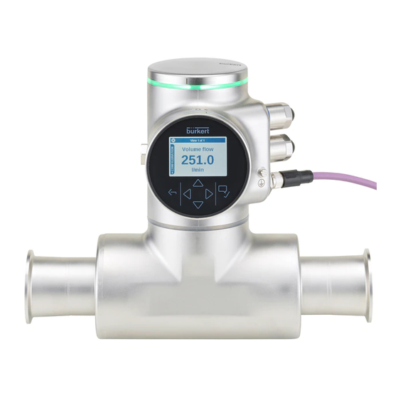
- Page 1 Type 8098 FLOWave L SAW Flowmeter QUICKSTART - English Software version A.03.10.00 and higher...
- Page 2 We reserve the right to make technical changes without notice. © Bürkert SAS, 2015 - 2020 QUICKSTART 2009/06_EU-EN 00567159 / Original EN...
-
Page 3: Table Of Contents
Type 8098 FLOWave L TableofContents The QuicksTarT ....................................7 symbols used ..................................7 1.1 Definition of the term device ............................7 1.2 Definition of the term büs ..............................8 1.3 Validity of the Quickstart ..............................8 1.4 inTenDeD use ....................................9 2.1 Device with aTeX certification ............................9 Basic safeTy informaTion ..............................10 General informaTion ................................12 manufacturer's address and international contacts ..................12 4.1 4.2 Warranty conditions ................................12 4.3 information on the internet ............................12 DescripTion ....................................13 Device variants . - Page 4 Type 8098 FLOWave L fluid data ....................................23 6.3 measurement data ................................25 6.4 electrical data ..................................26 6.5 mechanical data ...................................28 6.6 specifications of the ethernet industrial communication ................29 6.7 6.7.1 Modbus TCP protocol ........................29 6.7.2 PROFINET protocol ...........................30 6.7.3 EtherNet/IP protocol ..........................31 6.7.4 EtherCAT protocol ..........................32 insTallaTion in a pipe ................................33 7.1 safety instructions ................................33 7.2 additional documentation ..............................34...
- Page 5 Type 8098 FLOWave L 8.10 Wiring the device through the m20x1,5 cable glands in stainless steel (device variant with cable glands) ..............................53 8.11 Wiring the device through the m20x1,5 cable glands in nickel plated brass (device variant with cable glands) ..............................55 8.12 connecting the functional earth (device variant with two m20x1,5 cable glands) ......57 8.13 connecting the device to a 12...35 V Dc power supply through the m20x1,5 cable glands (device variant with cable glands) ......................58 8.14 Wiring output 1 (analogue) and output 3 configured as an analogue output (device variant with cable glands) ..............................59 8.15 Wiring output 2 (digital) and output 3 configured as a digital output (device variant with cable glands) ................................60 8.16 knowing the status of the ethernet network (device variant with two 4-pin m12 female connectors - ethernet device variant) .....................61 8.17 specifications of the cables and conductors for the 4-pin m12 female connectors .....62 8.18 connecting the device to an ethernet network (device variant with two 4-pin m12 female connectors - ethernet device variant) .....................62 8.19 connecting the functional earth (device variant with two 4-pin m12 female con- nectors - ethernet device variant) ..........................63 hoW To Do The seTTinGs ..............................64 9.1 safety instructions ................................64 9.2 available software to do the settings ........................64 9.3...
- Page 6 Type 8098 FLOWave L 9.8 how to navigate in the menus and to adjust values ..................75 9.8.1 Adjusting a percentage or selecting a value in a list ..............75 9.8.2 Navigating in a wizard and adjusting numbers ................76 9.8.3 Setting negative or positive numbers ....................77 9.8.4 Entering a name ..........................78 9.8.5 Activating or deactivating a feature ....................79 Doing the Quick start adjustments when energizing the device for the first time...
-
Page 7: The Quickstart
Fully read the Quickstart. In particular, observe the safety recommendations and intended use. ▶ The Quickstart must be read and understood. The full Operating Instructions are available on the internet at country.burkert.com symbols used Danger Warns against an imminent danger. ▶ Failure to observe this warning results in death or in serious injury. -
Page 8: Definition Of The Term Büs
"Guide for planning büS networks". → For more information on CANopen which is related to the device, refer to the Operating Instructions "CANopen Network configuration" at country.burkert.com. Validity of the Quickstart The Quickstart is valid for the devices from software version A.03.10.00. -
Page 9: Intended Use
▶ Observe the specifications of the ATEX-conformity certificate. ▶ Observe the specifications in the ATEX supplement for Type 8098 FLOWave L. The supplement is available at country.burkert.com. The ATEX certification is only valid if the device is used as described in the ATEX supplement. -
Page 10: Basic Safety Information
Type 8098 FLOWave L Basicsafetyinformation Basic saFeTy inFOrmaTiOn This safety information does not take into account any contingencies or occurrences that may arise during instal- lation, use and maintenance of the product. The operating company is responsible for the respect of the local safety regulations, including staff safety. - Page 11 ▶ Do not use the device in an environment incompatible with the device materials. ▶ Do not use fluid that is incompatible with the device materials. Find the compatibility chart on our homepage: country.burkert.com ▶ Do not subject the device to mechanical loads.
-
Page 12: General Information
You may also contact your local Bürkert sales office. The addresses of our international sales offices are available on the internet at: country.burkert.com Warranty conditions The condition governing the legal warranty is the conforming use of the device in observance of the operating conditions specified in the Operating Instructions. -
Page 13: Description
Type 8098 FLOWave L Description DescripTiOn Device variants The Type 8098 FLOWave L flowmeter is made up of a Type SE98 transmitter and a Type S097 flow sensor. The following pictures describe the main device variants of the Type 8098 FLOWave L flowmeter: •... - Page 14 Type 8098 FLOWave L Description Blind cover or display module (Type ME31) Device status indicator, seal Transmitter housing, including the electronic modules Type SE98 transmitter Seal 4-pin M12 female connectors with screwed plugs 5-pin M12 male connector, with screwed plug Functional earth Blind cover Seal...
-
Page 15: Wi-Fi Module
Type 8098 FLOWave L Description Wi-Fi module The device can be equipped with a Wi-Fi module in place of or in addition to the display module. The Wi-Fi module has the Type number ME31, too. The Wi-Fi module has the same functional scope as the display module. The Wi-Fi module is intended for use in Europe, the USA, and Canada. -
Page 16: Type Labels
Type 8098 FLOWave L Description Type labels 5.4.1 adhesive labels 8098 FLOWave L Supply: 12-35 5W Max. IP65 / IP67 / NEMA4X Ambient Temp : -10 to 70°C CAN_H 88888888 SN 9999 CAN_L CAN shield W49MN Made in France 28-06 1. - Page 17 Type 8098 FLOWave L Description 8098 FLOWave L IP65 / IP67 / NEMA 4X Ambient temp.: -10 to 55°C 88888888 SN 9999 CAN_H CAN_L CAN shield W49MN Made in France 28-06 1. IP-Code, NEMA protection type 7. Conformity marking 2. Type of the device 8.
-
Page 18: Laser Marking
Type 8098 FLOWave L Description 5.4.2 Laser marking Supply: 12...35V 5W Max. IP65 | IP67 | NEMA4X Ambient Temp: -10°...+70°C Type: 8098 FLOWave L ID:00xxxxxx | S/N:001234 Slot5: Slot4: W49MN Slot3: Slot2: Slot1: 28-06 Measuring CRN 0C21751.5 Equipment N°E237737 1. Type of the device 8. -
Page 19: Marking Of The Unique Serial Number (Usn)
Type 8098 FLOWave L Description marking of the unique serial number (usn) The USN is marked on the side of the sensor. The USN is built with the device article number and the device serial number. Device status indicator Ex works, the device status indicator changes its colour and state based on the NAMUR NE 107 recommendation. If several states exist simultaneously, the state with the highest priority is displayed. -
Page 20: Technical Data
• Unused M12 connectors must be protected by a screwed plug. not evaluated by UL → For the special operating conditions of devices with ATEX certification, refer to the ATEX supplement for the device. The supplement is available at country.burkert.com. English... -
Page 21: Conformity To Standards And Directives
Type 8098 FLOWave L Technicaldata conformity to standards and directives The applied standards, which verify conformity with the EU Directives, can be found on the EU Type Examination Certificate and/or the EU Declaration of Conformity (if applicable). 6.2.1 conformity to the pressure equipment Directive ▶... -
Page 22: Ehedg Certification
→ To make sure you use EHEDG-compliant gaskets, refer to the "EHEDG Position Paper" available on the EHEDG website. The manufacturer of the device does not supply any gaskets for the process connections. 6.2.4 aTeX certification → Refer to the ATEX supplement for the device. The supplement is available at country.burkert.com. English... -
Page 23: Fluid Data
Type 8098 FLOWave L Technicaldata Fluid data °C Ambient temperature Temperatures authorized for a limited duration °C Fluid temperature Fig. 9 : Dependency between the fluid temperature and the ambient temperature, device variant with two M20x1,5 cable glands and one 5-pin M12 male connector °C Ambient temperature Temperatures authorized for a limited duration °C Fluid temperature Fig. 10 : Dependency between the fluid temperature and the ambient temperature, device variant with two 4-pin M12 female connectors and one 5-pin M12 male connector (Ethernet device variant) fluid temperature –20...+110 °C. Up to 140 °C for maximum 60 minutes for a sterilisation process. - Page 24 Type 8098 FLOWave L Technicaldata size of the process Type of process standards the process connections connection connection conform to • DIN 11864-3 series B clamp • DIN 32676 series A PN25 DN08, DN15, DN25 • DIN 32676 series B flange DIN 11864-2 series B PN25 clamp DIN 11864-3 series A PN25 DN15, DN25 flange...
-
Page 25: Measurement Data
Type 8098 FLOWave L Technicaldata measurement data flow rate measurement • Measurement range • 0...1.7 m /h to 0...90 m /h, depending on the DN of the sensor • Measurement deviation for a flow rate • ±0.4% of the measured value 1) 2) between 10% of the full scale and the full scale •... -
Page 26: Electrical Data
Type 8098 FLOWave L Technicaldata electrical data Voltage not allowed Ambient temperature °C Temperature authorized for a limited duration Supply voltage V DC Fluid temperature °C Fig. 11 : Minimum supply voltage depending on the ambient temperature and the fluid temperature, device variant with two M20x1,5 cable glands and one 5-pin M12 male connector Voltage not allowed Ambient temperature °C Temperature authorized for a limited duration Supply voltage V DC Fluid temperature °C Fig. 12 :... - Page 27 Type 8098 FLOWave L Technicaldata Operating voltage • 12...35 V DC; the minimum voltage to be supplied depends on the fluid temperature and on the ambient oper- ating temperature: depending on your device variant, see Fig. 11 or Fig. 12 •...
-
Page 28: Mechanical Data
• Overload information through diagnostics software function • Protected against overloads • Protected against polarity reversals mechanical data Dimensions and weight of the device: refer to the technical data sheet regarding Type 8098 FLOWave L available country.burkert.com Table 3: Materials in contact with ambient air component material... -
Page 29: Specifications Of The Ethernet Industrial Communication
Input (Target to Originator) • All diagnostics and errors information has the highest priority and can be read by a PLC (refer to the concerned protocol file available at country.burkert.com). • PDO: value, status, unit • Device and modules: status •... -
Page 30: Profinet Protocol
• All diagnostics and errors information has the IO-supervisor) highest priority and can be read by a PLC (refer to the concerned protocol file available at country.burkert.com). • PDO: value, status, unit • Device and modules: status • Functions: value, status... -
Page 31: Ethernet/Ip Protocol
Input (Consumer to Producer or Adapter to Scanner) • All diagnostics and errors information has the highest priority and can be read by a PLC (refer to the con- cerned protocol file available at country.burkert.com). • PDO: value, status, unit • Device and modules: status •... -
Page 32: Ethercat Protocol
Type 8098 FLOWave L Technicaldata 6.7.4 ethercaT protocol Industrial Ethernet interface X1, X2 • X1: EtherCAT IN • X2: EtherCAT OUT Maximum number of cyclic input and output data 512 bytes in total Maximum number of 1024 bytes cyclic input data Maximum number of 1024 bytes cyclic output data... -
Page 33: Installation In A Pipe
Type 8098 FLOWave L Installationinapipe insTaLLaTiOn in a pipe safety instructions Danger risk of injury due to electrical voltage. ▶ Before carrying out work on the system, disconnect the electrical power for all the conductors and isolate it. ▶ In accordance with standard UL/EN 61010-1, all equipment connected to the Type 8098 FLOWave L flowmeter shall be double insulated with respect to the mains and all circuits connected to the Type 8098 FLOWave L flowmeter must be limited energy circuits. -
Page 34: Additional Documentation
→ If the device is an ATEX device variant, then refer to the ATEX supplement for Type 8098 FLOWave L available on the internet at country.burkert.com. preparing the device before installation into the pipe The device is delivered as described in chpt. 5.1. - Page 35 Type 8098 FLOWave L Installationinapipe Fig. 13 : Possible positions of the transmitter SE98 → To change the position of the transmitter, do the following: For safety reasons and to comply with standard UL 61010-1, the blind cover and the display module are locked. → Prepare the unlocking magnetic key, which is delivered with the device, to change the position of The blind cover or the display module is the transmitter.
- Page 36 Type 8098 FLOWave L Installationinapipe Carefully lift the display module because a cable connects the display module to the transmitter. 4. Push the tab of the cable connector to disconnect the display module from the transmitter. 5. Remove the display module and put it on a clean surface to protect the seal from dirt.
- Page 37 Type 8098 FLOWave L Installationinapipe Lift the transmitter carefully because a cable connects the transmitter to the flow sensor. 9. If the seal is damaged, replace it. Apply a layer of lithium soap grease to the new seal before you put it in place.
-
Page 38: Switching Positions Of The Blind Cover And The Display Module
Type 8098 FLOWave L Installationinapipe 14. Screw the transmitter clockwise on the flow sensor until the blind cover is perfectly parallel or perpen- dicular to the axis of the pipe. 15. Fasten the screw with a size 3 hexagonal key to a tightening torque of 1.3 N·m ±0.5 N·m (0.9 ft·lbf ±0.4 ft·lbf) 16. - Page 39 Type 8098 FLOWave L Installationinapipe For safety reasons and to comply with standard UL 61010-1, the blind cover and the display module are locked. → Prepare the unlocking magnetic key, which is delivered with the device. The blind cover or the display module is locked 1.
- Page 40 Type 8098 FLOWave L Installationinapipe 6. Put the magnetic key on the mark related to the blind cover. You should hear a click indicating that the blind cover is unlocked. Do not use a tool to turn the blind cover. 7.
-
Page 41: Recommendations For The Installation Into The Pipe
→ Make sure the DN of the measurement tube is suited to the flow velocity: refer to the data sheet of the device, available at country.burkert.com. The device is not intended to measure the flow rate of liquids if gas bubbles are present, whatever the origin of the bubbles (air intake, cavitation, degassing…). - Page 42 Type 8098 FLOWave L Installationinapipe Table 7: Minimum angle against the horizontal for proper self-draining angle against the Type of process connection standards the process connections conform to horizontal • DIN 32676 series A • DIN 11864-3 series A clamp minimum 5° • SMS 3017 / ISO 2852 for pipes according to SMS 3008 flange DIN 11864-2 series A minimum 5°...
- Page 43 Type 8098 FLOWave L Installationinapipe → To make sure the internal temperature of the transmitter with cable glands does not exceed the authorized maximum value, install the device as recommended in Fig. 16. → To make sure the internal temperature of the transmitter does not exceed the authorized maximum value, install an Ethernet device variant as recommended in Fig.
-
Page 44: Installing The Device Into The Pipe
Type 8098 FLOWave L Installationinapipe installing the device into the pipe CaUTiOn risk of injury due to a heavy device. A heavy device can fall down during transport or during installation and cause injuries. ▶ Transport, install and dismantle a heavy device with the help of another person. ▶... -
Page 45: Electrical Installation
Type 8098 FLOWave L Electricalinstallation eLecTricaL insTaLLaTiOn safety instructions Danger risk of injury due to electrical voltage. ▶ Before carrying out work on the system, disconnect the electrical power for all the conductors and isolate it. ▶ In accordance with standard UL/EN 61010-1, all equipment connected to the Type 8098 FLOWave L flowmeter shall be double insulated with respect to the mains and all circuits connected to the Type 8098 FLOWave L flowmeter must be limited energy circuits. - Page 46 Type 8098 FLOWave L Electricalinstallation Warning risk of injury due to unintentional switch on of the power supply or uncontrolled restart of the installation. ▶ Take appropriate measures to avoid unintentional activation of the installation. ▶ Guarantee a set or controlled process restart after carrying out any intervention on the device. CaUTiOn risk of injury due to a heavy device. A heavy device can fall down during transport or during installation and cause injuries. ▶...
-
Page 47: Additional Documentation
Network configuration" at country.burkert.com. • If the device is an ATEX device variant, then refer to the ATEX supplement for Type 8098 FLOWave L available on the internet at country.burkert.com. connecting the device to a power supply The device is wired in the factory to be easily energized through the 5-pin M12 male connector. -
Page 48: Connecting The Device To A Büs / Canopen Network
Type 8098 FLOWave L Electricalinstallation Voltage not allowed Ambient temperature °C Temperature authorized for a limited duration Supply voltage V DC Fluid temperature °C Fig. 19 : Minimum supply voltage depending on the ambient temperature and the fluid temperature, device variant with two 4-pin M12 female connectors and one 5-pin M12 male connector (Ethernet device variant) connecting the device to a büs / canopen network For a correct operation of the device, use a 5-pin M12 female connector in stainless steel with shield connection. The büS cable that is available from Bürkert has an external diameter of 8.2 mm. -
Page 49: Activating The Device Internal Termination Resistor
Type 8098 FLOWave L Electricalinstallation If a device with two 4-pin M12 female connectors (Ethernet device variant) is connected to an Ethernet network, you must connect it to a büS / CANopen network for the configuration of the device with the software Bürkert Communicator. -
Page 50: Specifications Of The Cables For The M20X1,5 Cable Glands (Device Variant With Cable Glands)
Type 8098 FLOWave L Electricalinstallation → Termination resistor → → Save. The internal termination resistor is activated. specifications of the cables for the m20x1,5 cable glands (device variant with cable glands) Table 8: Specifications of the cables for the M20x1.5 cable glands in nickel plated brass specification of the cables recommended value Electromagnetic protection (EMC) Shielded Diameter 5...14 mm Maximum operating temperature 90 °C or higher Table 9:... -
Page 51: Terminal Assignment Of The 12 Push-In Terminal Strip
Type 8098 FLOWave L Electricalinstallation Terminal assignment of the 12 push-in terminal strip The terminal strip located in the transmitter housing has 12 push-in terminals. Fig. 22 : Wiring ex works of the 12 push-in terminal strip → To access the 12 push-in terminal strip, open the front of the transmitter; See chpt. 8.9. →... -
Page 52: Opening The Front Of The Transmitter
Type 8098 FLOWave L Electricalinstallation Opening the front of the transmitter To open the front of the transmitter housing, remove either the blind cover or the display module. procedure to open the front of the transmitter if the blind cover is on the front of the device 1. Put the magnetic key on the mark related to the blind cover. You should hear a click indicating that the blind cover is unlocked. -
Page 53: Wiring The Device Through The M20X1,5 Cable Glands In Stainless Steel (Device Variant With Cable Glands)
Type 8098 FLOWave L Electricalinstallation 8.10 Wiring the device through the m20x1,5 cable glands in stainless steel (device variant with cable glands) Put only one cable in each cable gland. → Prepare cables that obey the specifications given in chpt. 8.6 and chpt. 8.7. →... - Page 54 Type 8098 FLOWave L Electricalinstallation 12. Put the functional earth plate in its original place. Functional earth 13. Use a size 10 hexagonal key to tighten the 2 screws of the functional earth plate to a torque of 0.2 N·m (0.15 ft·lbf).
-
Page 55: Wiring The Device Through The M20X1,5 Cable Glands In Nickel Plated Brass (Device Variant With Cable Glands)
Type 8098 FLOWave L Electricalinstallation 8.11 Wiring the device through the m20x1,5 cable glands in nickel plated brass (device variant with cable glands) Put only one cable in each cable gland. → Prepare cables that obey the specifications given in chpt. - Page 56 Type 8098 FLOWave L Electricalinstallation 9. If the cable diameter is between 9 and 14 mm, → vertically put a screwdriver between the two seals, → lift the inner seal and remove it. → Put the cable through the cable gland. →...
-
Page 57: Connecting The Functional Earth (Device Variant With Two M20X1,5 Cable Glands)
Type 8098 FLOWave L Electricalinstallation 13. Put each conductor in the correct terminal of the terminal strip. 14. To connect the 12...35 V DC power supply through the cable glands, refer to chpt. 8.13. 15. To connect the outputs, refer to chpt. 8.14 and chpt. 8.15. 16. -
Page 58: Connecting The Device To A 12
Type 8098 FLOWave L Electricalinstallation 8.13 connecting the device to a 12...35 V Dc power supply through the m20x1,5 cable glands (device variant with cable glands) 1. Use a 3.0 mm slot screwdriver (any length) and a force of max. 40 N to push the terminal 5 and disconnect the white conductor. -
Page 59: Variant With Cable Glands)
Type 8098 FLOWave L Electricalinstallation Fig. 30 : Device connected to a 12...35 V DC power supply through the M20x1,5 cable glands 8.14 Wiring output 1 (analogue) and output 3 configured as an analogue output (device variant with cable glands) nOTiCe risk of short-circuit if the configuration of output 3 is wrong. ▶ Before wiring output 3 as an analogue output, make sure output 3 is configured as an analogue output in the Parameter menu of the outputs. -
Page 60: Wiring Output 2 (Digital) And Output 3 Configured As A Digital Output (Device Variant With Cable Glands)
Type 8098 FLOWave L Electricalinstallation 8.15 Wiring output 2 (digital) and output 3 configured as a digital output (device variant with cable glands) nOTiCe risk of short-circuit if the configuration of output 3 is wrong. ▶ Before wiring output 3 as a digital output, make sure output 3 is configured as a digital output in the Param- eter menu of the outputs. -
Page 61: Knowing The Status Of The Ethernet Network (Device Variant With Two 4-Pin M12 Female Connectors - Ethernet Device Variant)
Type 8098 FLOWave L Electricalinstallation 8.16 knowing the status of the ethernet network (device variant with two 4-pin m12 female connectors - ethernet device variant) The status of the Ethernet network is indicated by LEDs. The LEDs are located on the industrial communication module in the transmitter housing. -
Page 62: Specifications Of The Cables And Conductors For The 4-Pin M12 Female Connectors
Type 8098 FLOWave L Electricalinstallation 8.17 specifications of the cables and conductors for the 4-pin m12 female connectors Table 13: Specifications of the cables and conductors for the 4-pin M12 female connectors specification of the cables and conductors recommended value Electromagnetic protection (EMC) Shielded conductor with minimum STP Minimum category CAT-5 Maximum length 100 m Maximum operating temperature 90 °C or higher 8.18 connecting the device to an ethernet network... -
Page 63: Connecting The Functional Earth (Device Variant With Two 4-Pin M12 Female Connectors - Ethernet Device Variant)
Type 8098 FLOWave L Electricalinstallation Cable and conductors con- nected inside the device from X1 to the upper 4-pin M12 female connector Cable and conductors con- nected inside the device from X2 to the middle 4-pin M12 female connector Cable and conductors connected inside the device from the 12 push-in terminal strip to the 5-pin M12 male connector Fig. 35 :... -
Page 64: How To Do The Settings
→ To use some specific functions that are only available with the Bürkert Communicator software, refer to the Type 8920 Operating Instructions, available on the internet at country.burkert.com → To get detailed information on the software of the Type ME31 display module, refer to the related Operating Instructions, available on the internet at country.burkert.com... - Page 65 Type 8098 FLOWave L Howtodothesettings 7. Insert the appropriate power adapter into the AC/DC adapter. 8. Connect the cable of the AC/DC adapter to the related connector of the female M12 connector. Termination Female M12 resistance connector büS stick Power adapter Y plug AC/DC adapter mini-USB...
-
Page 66: Display Module: Description Of The User Interface
To get detailed information on the display software, refer to the Operating Instructions of the Type ME31 display software, available on the internet at country.burkert.com The user interface is made up of a display and touch sensitive keys. View 1 of 4... -
Page 67: Description Of The Display
Type 8098 FLOWave L Howtodothesettings 9.4.1 Description of the display Symbol of the active user level. See chpt. 9.5 Available login user levels. Symbol of the device status Information bar Display parameter To the DIAG- Brightness NOSTICS menu, by Contrast pressing Screen saver Name of the customized view or of the menu... -
Page 68: How To Use The Touch Sensitive Keys
Type 8098 FLOWave L Howtodothesettings 9.4.2 how to use the touch sensitive keys highlighted terms are related to menus or menu items. Table 14: How to use the keys Description Short press: to go back to the parent menu or to the parent view. This key is called BACK in the display messages. -
Page 69: Default Settings
You can find the default settings of the device in the CANopen supplement for the Type 8098 FLOWave L at country.burkert.com. → Before making any changes to the settings, use the Bürkert Communicator software to print a pdf file with all the default settings of the device. -
Page 70: Menu Structure
Type 8098 FLOWave L Howtodothesettings menu structure View 1 of 4 CONFIGURATION Volume flow 30.1 SAW sensor To navigate through the list of l/min available menu items Configuration view First view, displayed after energizing the device, that can be changed by the user Press to access the displayed menu item (for example, the item "SAW sensor") -
Page 71: Opening Or Closing The Context Menu In Any View (Display Module Only)
Type 8098 FLOWave L Howtodothesettings 9.7.1 Opening or closing the context menu in any view (display module only) The user can open a context menu in any view. The content depends on the active view. To open the context menu: →... -
Page 72: Adding Your Own Context Menu Items (Shortcuts, Display Module Only)
Type 8098 FLOWave L Howtodothesettings View menu items of the context menu messages overview To display the list of messages generated by the device. save To save the changes. To display the access path to the displayed menu item. Not Where am i? available in the wizard. in a menu add shortcut To create or delete your own context menu items (see chpt. -
Page 73: Reading Out The Messages Generated By The Device
→ To read out the messages in the Bürkert Communicator software, refer to the Type 8920 Operating Instruc- tions, available on the internet at country.burkert.com. Do the following to display the generated messages on the display module: →... -
Page 74: Changing The Login User Level If The Adjustment Is Protected Through Passwords
→ To change the login user level in the Bürkert Communicator software, refer to the Type 8920 Operating Instructions, available on the internet at country.burkert.com. Do the following to change the login user level on the display module: →... -
Page 75: Reading Out The Access Path To A Menu Item (Display Module Only)
Type 8098 FLOWave L Howtodothesettings 9.7.7 reading out the access path to a menu item (display module only) If you are lost in the menu structure, you can display the access path. → Long press, to open the context menu. →... -
Page 76: Navigating In A Wizard And Adjusting Numbers
Type 8098 FLOWave L Howtodothesettings 9.8.2 navigating in a wizard and adjusting numbers General settings parameter Quick start Diagnostics Date and time Language English Confirm Parameter Current date/time 1/9 Current date:08/24/15 Current time:08:57:16 Daylight savings Current time zone:+00:London Go back to the previous screen (available at each step of the wizard) Confirm to go to the next screen. -
Page 77: Setting Negative Or Positive Numbers
Type 8098 FLOWave L Howtodothesettings 9.8.3 setting negative or positive numbers Settings Error low max: 150.00 -020.000 min: -20.00 To set a positive number: → to increase the number until the positive value is reached. Settings Error low max: 150.00 010.000 min: -20.00 To set a negative number:... -
Page 78: Entering A Name
Type 8098 FLOWave L Howtodothesettings 9.8.4 entering a name SAW sensor parameter stand. meas. values [ +] Add. meas. values [+] Diag. events Refresh time Long Confirm SAW sensor stand. meas. values Volume flow Temperature Liquid velocity Totalizer 1 Confirm SAW sensor Volume flow Value name Volume flow Damping ... -
Page 79: Activating Or Deactivating A Feature
Type 8098 FLOWave L Howtodothesettings 9.8.5 activating or deactivating a feature General settings parameter Date and Time Language English Passwords Physical units Confirm Parameter passwords Password protection Confirm Passwords password protection Deactivate / Activate Save Fig. 46 : Activating or deactivating a feature English... -
Page 80: Doing The Quick Start Adjustments When Energizing The Device For The First Time (Display Module Only)
Type 8098 FLOWave L Howtodothesettings Quick start Doing the adjustments when energizing the device for the first time (display module only) When the device is energized for the first time, the user is guided to make the following mandatory settings: • choosing the display language, •... -
Page 81: Changing The Type Of Output 3
Type 8098 FLOWave L Howtodothesettings 9.10 changing the type of output 3 nOTiCe risk of short-circuit if the configuration of output 3 is wrong. ▶ Before wiring the output 3, make sure the output 3 is correctly configured. The output parameters can be set with the installer user level. Even if the menu Outputs is available on an Ethernet device variant, we recommend to not use the outputs. -
Page 82: Maintenance And Troubleshooting
Type 8098 FLOWave L Maintenanceandtroubleshooting mainTenance anD TrOuBLeshOOTinG 10.1 safety instructions risk of injury due to electrical voltage. ▶ Before carrying out work on the system, disconnect the electrical power for all the conductors and isolate it. ▶ In accordance with standard UL/EN 61010-1, all equipment connected to the Type 8098 FLOWave L flowmeter shall be double insulated with respect to the mains and all circuits connected to the Type 8098 FLOWave L flowmeter must be limited energy circuits. -
Page 83: Information On Returning The Device To The Manufacturer Or To The Reseller
→ To return the device for calibration or any after sales service, use the original packaging. → Send the device back to your local Bürkert sales office. The addresses of our international sales offices are available on the internet at country.burkert.com. 10.3 cleaning the outer surface of the device •... -
Page 84: Sterilisation In Place (Sip) Of The Device
Type 8098 FLOWave L Maintenanceandtroubleshooting - for a duration that is determined by your CIP recipe. → Rinse the measurement tube with water of the best quality available in the factory (ideally, water for injection or purified water) under the same conditions as the first rinse. →... -
Page 85: Troubleshooting When A Message Is Displayed
Type 8098 FLOWave L Maintenanceandtroubleshooting 10.7 Troubleshooting when a message is displayed → If the message displayed on your device is not explained in the Operating Instructions, contact Bürkert. If a message has been generated: • a symbol is displayed in the information bar: see Table 17. •... -
Page 86: Spare Parts And Accessories
Type 8098 FLOWave L Sparepartsandaccessories spare parTs anD accessOries CaUTiOn risk of injury and/or damage caused by the use of unsuitable parts. Incorrect accessories and unsuitable replacement parts may cause injuries and damage the device and the sur- rounding area. ▶ Use only original accessories and original replacement parts from Bürkert. spare part or accessory article number Unlocking magnetic key... -
Page 87: Packaging, Transport
Type 8098 FLOWave L Packaging,Transport packaGinG, TranspOrT CaUTiOn risk of injury due to a heavy device. A heavy device can fall down during transport or during installation and cause injuries. ▶ Transport, install and dismantle a heavy device with the help of another person. ▶ Use appropriate tools. nOTiCe Damage due to transport Transport may damage an insufficiently protected device. - Page 88 Type 8098 FLOWave L English...
- Page 90 www.burkert.com...
Need help?
Do you have a question about the FLOWave L 8098 and is the answer not in the manual?
Questions and answers