
Related Manuals for Burkert FLOWave S 8098


Summary of Contents for Burkert FLOWave S 8098
- Page 1 Type 8098 FLOWave S Durchflussmessgerät Flowmeter Débitmètre Quickstart English Deutsch Français...
- Page 2 We reserve the right to make technical changes without notice. Technische Änderungen vorbehalten. Sous réserve de modifications techniques. © Bürkert Werke GmbH & Co. KG, 2019 Operating Instructions 1912/00_EU-ML_00815331 / Original DE...
-
Page 3: Table Of Contents
Type 8098 Table of contents ELECTRICAL INSTALLATION ..........20 ABOUT THESE INSTRUCTIONS .......... 4 8.1 Safety instructions ............. 20 Symbols ............... 4 8.2 Requirements for electrical installation ..... 20 1.2 Definition of terms ............4 8.3 Additional documentation ......... 21 INTENDED USE ..............5 8.4 Connection to supply voltage or supply voltage BASIC SAFETY INSTRUCTIONS .......... 5 and communication ........... -
Page 4: About These Instructions
▶ Failure to observe the warning may result in damage to the ▶ Observe in particular the safety instructions, intended use and device or system. operating conditions. ▶ Persons, who work on the device, must read and understand Indicates important additional information, tips and these instructions. recommendations. The operating instructions can be found on the Internet at: Refers to information in these instructions or in other www.burkert.com documentation. Symbols ▶ Designates an instruction to prevent risks. → designates a procedure that must be carried out. DANGER! Indicates a result. Warns of an immediate danger. ▶ Failure to observe the warning may result in a fatal or serious Definition of terms injury. -
Page 5: Intended Use
Type 8098 Intended use INTENDED USE BASIC SAFETY INSTRUCTIONS These safety instructions do not consider any contingencies or inci- The Type 8098 flowmeter is intended to measure the flow rate dents which occur during installation, operation and maintenance. of clean liquids, non emulsified (homogeneous liquids) and free of air bubbles and free of gas bubbles and free of solids, The operator is responsible for observing the location-specific safety regulations, also with reference to the personnel. - Page 6 Type 8098 Basic safety instructions CAUTION ATTENTION! Electrostatic sensitive components or modules. Risk of injury due to a heavy device. The device contains electronic components which react sen- A heavy device can fall down during transport or during instal- sitively to electrostatic discharge (ESD). Contact with electro- lation and cause injuries. statically charged persons or objects is hazardous to these ▶...
-
Page 7: General Information
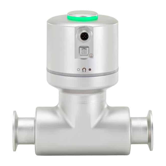
Germany Electrical connection Bürkert SAS Rue du Giessen Grounding connection BP 21 (protective earth) F-67220 TRIEMBACH-AU-VAL Transmitter Seal International Sensor housing Contact addresses can be found on the final pages of the printed Process connection operating instructions. And also on the Internet at: www.burkert.com Fig. 1: Structure Warranty The Type 8098 flowmeter is made up of a Type SE91 transmitter The warranty is only valid if the device is used as intended in accor- and a Type S097 flow sensor. dance with the specified application conditions. The device is delivered with a magnetic key to unlock the transmitter. Information on the internet The operating instructions and data sheets for Type 8098 can be found on the Internet at: www.burkert.com Fig. 2: Unlocking magnetic key english... -
Page 8: Technical Data
Type 8098 Technical data TECHNICAL DATA Conformity In accordance with the EU Declaration of conformity, the device Operating conditions is compliant with the EU Directives. Ambient temperature -10 – +70 °C Standards Air humidity < 85%, non condensing The applied standards, which verify conformity with the EU Operating altitude Up to 2000 m above sea level Directives, can be found on the EU-Type Examination Certificate and / or the EU Declaration of Conformity. Operating mode Continuous operation Device mobility Fixed device 6.3.1 Conformity to the Pressure Equipment Use I ndoor and outdoor (with pro- Directive tection against electromagnetic The device conforms to Article 4, Paragraph 1 of the Pressure interference, ultraviolet rays and Equipment Directive 2014/68/EU under the following conditions: weather conditions) Device used on a pipe (PS = maximum admissible pressure in Installation category C ategory I according to UL/... -
Page 9: Ehedg Certification
Type 8098 Technical data 6.3.2 UL certification Process connections Diameters The devices with variable key PU01 or PU02 are UL-certified devices Clamp connections according DN15 (except variants with a and comply with the following standards: to DIN 32676 series B clamp diameter of 34.0 mm) • UL 61010-1 DN25, DN40, DN50 • CAN/CSA-C22.2 n°61010-1 Clamp connections according DN15, DN25, DN40, DN50 to DIN 32676 series A Identification on the Certification Variable key device Clamp connections according DN15, DN25, DN40, DN50 to DIN 11864-3 series A, DIN 11864-3 series B UL recognized PU01 Clamp connections according DN25, DN40, DN50 to SMS 3017 / ISO 2852 for Measuring... -
Page 10: Type Label, Adhesive Label
Type 8098 Technical data Type label, adhesive label S097 FLOWave Flow sensor Pipe: 316L/1.4435 Housing: 304/1.4301 8098 FLOWave S DIN 11866 C / Clamp D50.5 DIN 32676 B DN15 Supply: 12-35 2.5W Max. IP65 / IP67 / NEMA4X PN25bar Max. flow:10 m3/h Ambient Temp : -10 to 70°C Temp. medium : -20 to 110°C CAN_H W4ZMN 88888888... -
Page 11: Type Label Lasered
Type 8098 Technical data Type label lasered Type: 8098 FLOWave S ID: 00566187 | S/N: 001234 W45MP November 2016 Fig. 6: Type label flow sensor (example) F-67220 Triembach Made in France Supply: 12...35V ; 2,5W Max IP65 | IP67 | NEMA 4X 1. -
Page 12: Fluid Data
Type 8098 Technical data Fluid data Process connection Ambient temperature °C Size Type Standards DN15, clamp DIN 11864-3 series A PN25 DN25 DIN 11864-3 series B DIN 32676 series A DIN 32676 series B Temperatures flange DIN 11864-2 series A PN25 authorized for a DIN 11864-2 series B limited duration DN25 clamp SMS 3017 / ISO 2852 for pipes PN25 according to SMS 3008 3/4'', 1'', clamp ASME BPE (DIN 32676 series C PN25 1 1/2'' DIN 11864-3 series C °C flange DIN 11864-2 series C PN25... -
Page 13: Measurement Data
Type 8098 Technical data Measurement data Process connection Flow rate measurement Size Type Standards Measurement range 0 – 7 m /h to DN50 clamp DIN 11864-3 series A PN16 0 – 90 m /h, DIN 11864-3 series B depending on the DIN 32676 series A DN of the sensor DIN 32676 series B Measurement deviation for a flow rate ±0.4 % of the 3) 4) SMS 3017 / ISO 2852 for pipes between 10 % of the full scale and the full measured value according to SMS 3008 scale flange DIN 11864-2 series A PN16 Measurement deviation for a flow rate < ±0.08 % of the 3) 4) DIN 11864-2 series B... -
Page 14: Electrical Data
Type 8098 Technical data Electrical data Density factor measurement (optional feature) Measurement range 0.8 – 1.3 Voltage not allowed Temperature authorized for a limited duration Resolution 0.00001 Ambient temperature °C Operating voltage V DC Repeatability ±0.5 % of the mea- sured value Refresh time Adjustable (Bürkert Communicator) Acoustic transmission factor measurement (optional feature) Measurement range 10 – 120 % Resolution 0.01 % Repeatability ±2 % of the mea- sured value Fluid temperature °C Refresh time Adjustable (Bürkert Communicator) Fig. 8: Minimum supply voltage depending on the ambient temperature and the fluid temperature 3) “Measurement bias”... -
Page 15: 6.10 Mechanical Data
Type 8098 Technical data Sensor body S tainless steel 304 / 1.4301, Connections C ircular plug-in connector (M12 x 1, outer surface finish Ra < 1.6 µm 5-pin) Operating voltage 1 2 – 35 V DC ±10% 5-pin M12 male connector Stainless steel the minimum voltage to be supplied Blind plug Stainless steel depends on the fluid temperature and on the ambient operating temperature: Seals see “Fig. 8” Filtered and regulated Sensor/transmitter Silicone Extra-Low Voltage circuit (SELV circuit) Transmitter/status indicator EPDM Limited Power Source (LPS) according Type label Polyester to standards UL/EN 60950-1 or through a limited-energy circuit according to Sensor measurement tube S tainless steel 316L / DIN 1.4435 standards UL/EN 61010-1 Current consumption max. 1 A Line connections S tainless steel 316L / DIN 1.4435... -
Page 16: Installation
Type 8098 Installation INSTALLATION CAUTION Safety instructions Risk of injury due to a heavy device. DANGER! A heavy device can fall down during transport or during instal- lation and cause injuries. Risk of injury from high pressure in the equipment/device. ▶ Transport, install and dismantle a heavy device with the help ▶ Before working on equipment or device, switch off the pressure of another person. and deaerate/drain lines. ▶ Use appropriate tools. ▶ Respect the regulations to the use of dangerous fluids. Risk of injury from electric shock. Preparatory work ▶... -
Page 17: Recommendations For The Installation Into The Pipe
20 degrees counterclockwise. transmitter is parallel or perpen- → Lift the transmitter carefully dicular to the axis of the pipe. because a cable connects the transmitter to the flow sensor. Recommendations for the installation → If the seal is damaged, replace into the pipe it. Apply a layer of lithium soap grease to the new seal before → Protect this device against electromagnetic interference, you put it in place. ultraviolet rays and, when installed outdoors, the effects of climatic conditions. → If the seal is not located in the groove, put it back in the → Make sure the DN of the measurement tube is suited to the groove. flow velocity: refer to the data sheet of the device, available at www.burkert.com. english... - Page 18 Type 8098 Installation → Choose a location with enough free space to put the magnetic Process connection key on the symbol at the side of the device. Angle against the horizontal → Install the device upstream a valve or any equipment that Type Standards changes the pipe diameter or the pipe direction. ASME BPE (DIN 32676 series C) The factory calibration of the FLOWave is done under reference DIN 32676 series A clamp minimum 3° conditions with inlet (40 x DN) and outlet (1 x DN) distances and DIN 11864-3 series B the appropriate internal diameter of the pipes. Deviation from DIN 11864-3 series C reference conditions can be adjusted through the use of a built-in DIN 11864-2 series B K factor adjustment or Teach in procedure. Please contact us. flange minimum 3° DIN 11864-2 series C → Install the device into either horizontal, oblique or vertical Tab. 5: Minimum angle against the horizontal for proper self-draining pipes. But an installation in a vertical pipe will be better to prevent air or gas bubbles inside the measurement area.
-
Page 19: Installing The Device Into The Pipe
Type 8098 Installation → To make sure the internal temperature of the transmitter does Installation: not exceed the authorized maximum value, install the device → Make sure the seals on the clamp connections are in good as recommended in “Fig. 11”. condition. → Place seals adapted to the process (temperature, fluid type) in the grooves of the clamp connections. → Attach the clamp connections to the pipe with clamp collars. 7.4.2 Installing a device with flange connections Not recommended Recommended The flange connections according to DIN 11864-2 series A, B and C are hygienic connections. 7) These orientations are valid for all the positions of →... -
Page 20: Electrical Installation
Type 8098 Electrical installation ELECTRICAL INSTALLATION CAUTION Safety instructions Risk of injury due to a heavy device. DANGER! A heavy device can fall down during transport or during instal- lation and cause injuries. Risk of injury from high pressure in the equipment/device. ▶ Transport, install and dismantle a heavy device with the help ▶ Before working on equipment or device, switch off the pressure of another person. and deaerate/drain lines. ▶ Use appropriate tools. ▶ Respect the regulations to the use of dangerous fluids. Risk of injury from electric shock. Requirements for electrical installation ▶... -
Page 21: Additional Documentation
Shielded → Double isolate all devices connected to the flow meter Type 8098 from the mains. Cross section of the conductors max. 0.75 mm → All circuits connected to the flow meter Type 8098 Diameter of the cable 3 – 6.5 mm must be limited energy circuits. Minimum required operating temperature min. 80 °C or higher M12 socket, 5-pin see accessories (order no. 917116). Additional documentation Further information on büS can be found in the cabling guide in Technical data for cables German and English at www.burkert.com. Search for “Guide for (supply voltage and bus/CANopen communication) planning büS networks”. Electromagnetic protection (EMC) Shield Further information on CANopen, which refers to the device, can Cross section of the conductors be found in the operating manual “CANopen Network Configu- Supply voltage max. 0.75 mm ration” at www.burkert.com. Communication max. 0.34 mm² Diameter of the cable max. 8.2 mm... -
Page 22: Connecting The Protective Earth
Type 8098 Electrical installation → If the device is connected to a büS network or to a CANopen 8.4.1 Cable assembling network and at one end of the büS network or of the CANopen → Put the cable through the network, either install a one or two 120 W termination resistors nut and the rear part of the in the line or activate the device internal termination resistorwith connector. software: see chapter “Activating the device internal terminating → Strip 20 mm of the cable. resistor” in the operating instructions. The büS or CANopen line → Cut the central wire (shield) must be adapted to 60 W. 11,5 11,5 to length 11.5 mm. The minimum voltage to be supplied depends on the fluid tem- → Expose 5.5 mm of the other conductors. perature and on the ambient operating temperature. → Connect wires according to pin assignment. Voltage not allowed → Reassemble the socket. Temperature authorized for a limited duration Connecting the protective earth Operating voltage V DC Ambient temperature °C For proper function of the device, connect the yellow/green conductor to... -
Page 23: Start-Up
Type 8098 Start-up START-UP 9.2.1 Connecting büS device with Bürkert Communicator Safety instructions Required components (see “12 Accessories”): WARNING! • Communications software: Bürkert Communicator for PC • USB-büS interface Risk of injury from improper operation. Improper operation may result in injuries as well as damage to Termination the device and the area around it. Y plug resistance ▶ Before start-up, ensure that the operating personnel are familiar with and completely understand the contents of the Female M12 operating instructions. büS stick connector ▶ Observe the safety instructions and intended use. ▶... -
Page 24: Büs
The status indicator show the device status. The user can set the following LED modes for the display of device status and valve position. 9.3.2 Configuration of the fieldbus • NAMUR mode (factory setting) The required start-up files and the description of objects are available on the Internet. • Fixed color • LED off Download from: www.burkert.com / Type 8098 / Software The LED mode and the colors of the valve position can be set with the Bürkert Communicator. The description for setting the LED mode can be found in the section "Changing the operating mode of the device status LED or switching off the status LED" in the oper- ating instruction. 10.2 NAMUR mode The display elements change color in accordance with NAMUR NE 107. If several device statuses exist simultaneously, the device status with the highest priority is displayed. The priority is determined... - Page 25 Type 8098 display elements Status indicator in accordance with NE 107, edition 2006-06-12 Status indicator in accordance with NE 107, edition 2006-06-12 Color Color Status Description Color Color Status Description code code White Diagnostics Device is switched on. Outage, error Normal operation is not pos- inactive or malfunction sible due to a malfunction in Status changes are not shown.
-
Page 26: Maintenance And Troubleshooting
▶ Before working on the device or system, switch off the power supply. Secure against reactivation. → To return the device for calibration or any after sales service, ▶ Observe applicable accident prevention and safety regulati- use the original packaging. ons for electrical equipment. → Send the device back to your local Bürkert sales office. The Risk of burns und risk of fire through hot device surface. addresses of our international sales offices are available on the internet at www.burkert.com ▶ Use safety gloves to handle the device. ▶ Keep the device away from highly flammable substances 11.3 Cleaning the outer surface of the and media. device WARNING! → Always use a cleaning agent compatible with the materials from which the device is made. -
Page 27: Cleaning In Place (Cip) Of The Device
Type 8098 Maintenance and troubleshooting 11.4 Cleaning In Place (CIP) of the device → Prepare one or two cleaning agents at concentrations and with chemical properties that have proven their effectiveness on the The measurement tube of the device can be cleaned in place in residues to be removed. Make sure the concentration of the all the applications the device is used in. cleaning agent does not damage stainless steel 316L. → Do the cleaning in place procedure at appropriate intervals to → Let the cleaning agent circulate through the measurement tube prevent malfunctions or contamination. under the following conditions: ATTENTION! - at a temperature between 50 °C and 75 °C, The device and the seals used on the process connections - at a flow velocity between 1,5 m/s and 2,1 m/s, can be damaged by the cleaning agents or the disinfecting - for a duration that is determined by your CIP recipe. -
Page 28: Sterilisation In Place (Sip) Of The Device
[3 – 5%] at a temperature between 70 °C and 80 °C Unlocking magnetic key 690309 circulate through the measurement tube for the same duration as the CIP-procedure. Then, rinse the measurement tube with 5-pin M12 female straight cable plug with 917116 water with the best quality available in the factory (ideally, water plastic threaded locking ring, to be wired for injection or purified water) under the same conditions as the Communication software Bürkert Information at other rinses. Communicator www.burkert.com → Blow air through the measurement tube to remove moisture and to ensure creation of a uniform passive layer. 11.5 Sterilisation In Place (SIP) of the device The measurement tube of the device can be sterilised in place in all the applications the device is used in. USB-büS interface set: 772426 → Do the sterilisation in place procedure using dry saturated steam at a temperature between 121 °C and 140 °C for max. 1 hour. büS cable extension (M12), length 1 m 772404 büS cable extension (M12), length 3 m... -
Page 29: Communications Software
Risk of injury due to a heavy device. A detailed description and precise schedule of the procedure for the installation and operation of the software can be found A heavy device can fall down during transport or during instal- in the associated documentation. lation and cause injuries. ▶ Transport, install and dismantle a heavy device with the help of another person. Download the software at: www.burkert.com ▶ Use appropriate tools. ATTENTION! Damage in transit due to inadequately protected devices. ▶ Protect the device against moisture and dirt in shock-resi- stant packaging during transportation. ▶ Observe permitted storage temperature. ATTENTION! Incorrect storage may damage the device. - Page 30 Type 8098 Transportation, storage, disposal ATTENTION! Damage to the environment caused by device components contaminated with media. ▶ Dispose of the device and packaging in an environmentally friendly manner. ▶ Observe applicable disposal and environmental regulations. Observe national regulations on the disposal of waste. ATTENTION! Damage to the environment due to parts contaminated by the fluid. • Dispose of the device and its packaging in an environmen- tally-friendly way. • Comply with the regulations which concern the area of waste disposal.
- Page 32 www.burkert.com...
Need help?
Do you have a question about the FLOWave S 8098 and is the answer not in the manual?
Questions and answers