Sign In
Upload
Manuals
Brands
Burkert Manuals
Measuring Instruments
FLOWave S
Burkert FLOWave S Manuals
Manuals and User Guides for Burkert FLOWave S. We have
1
Burkert FLOWave S manual available for free PDF download: Operating Instructions Manual
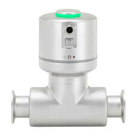
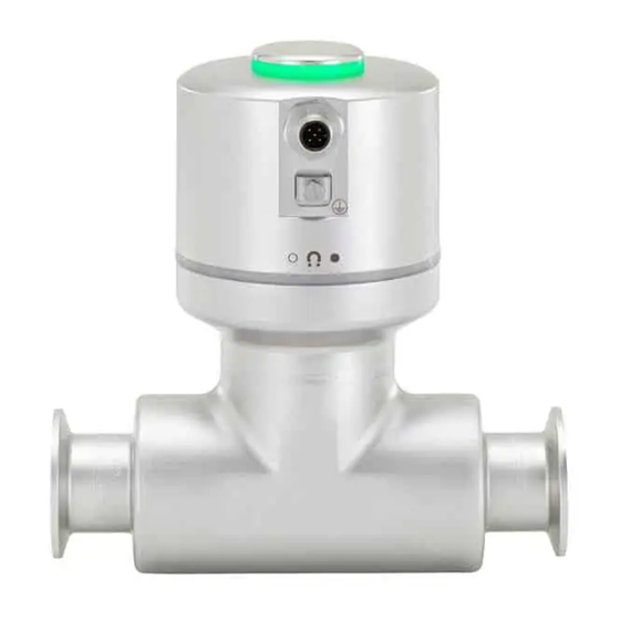
Burkert FLOWave S Operating Instructions Manual (241 pages)
Brand:
Burkert
| Category:
Measuring Instruments
| Size: 7 MB
Table of Contents
Symbols Used
18
Intended Use
19
Basic Safety Information
20
General Information
22
Manufacturer's Address and International Contacts
22
Warranty Conditions
22
Information on the Internet
22
Transmitter Variants
23
Unlocking Magnetic Key
23
Certification Markings
26
Technical Data
27
Operating Conditions
27
Standards and Directives
27
Conformity to the Pressure Equipment Directive
28
Measurement Data
32
Volume Flow Rate
32
Mass Flow Rate
33
Electrical Data
34
Mechanical Data
35
Installation in the Pipe
36
Safety Instructions
36
Changing the Position of the Transmitter on the Sensor
38
Before Installing the Device into the Pipe
41
Installing a Device with Clamp Connections
42
Installing a Device with Flange Connections
42
Electrical Installation
44
Additional Documentation
45
Connecting the Device to a Power Supply
46
Connecting the Protective Earth
50
Default Settings
52
Entering a Name for the Device
58
Entering the Location of the Device
58
Entering a Description for the Device
59
Entering a Unique Name for the Device
59
Changing the Transmission Speed on the Device
60
Activating the Device Internal Termination Resistor
60
Deactivating the Device Internal Termination Resistor
61
Stop Sending the Measured Process Data (Pdos) to Büs or to the Canopen Fieldbus
63
Reading out the 2 Error Limit Values
65
Changing the 2 Warning Limit Values
65
Reading out the Hysteresis Value
65
Reading out the Minimum or the Maximum Value of the Internal Temperature of the Device
69
Reading out the Current Value of the Supply Voltage
69
Reading out the Minimum or the Maximum Value of the Supply Voltage
69
Reading out the Minimum or the Maximum Value of the Current Consumption of the Device
70
Reading out the Number of Device Starts
70
Checking Whether the Date and Time Are Correct
71
Checking the Voltage of the Internal Battery
71
Reading out the Number of Current Receive Errors
72
Reading out the Maximum Number of Receive Errors Since the Last Power-Up of the Device
72
Reading out the Number of Current Transmit Errors
72
Reading out the Maximum Number of Transmit Errors Since the Last Power-Up of the Device
73
Resetting the 2 Maximum Error Counters
73
Reading out Whether the Measured Process Data (PDO, Process Data Object) Is Sent on Büs or on the Canopen Fieldbus
73
Reading out the Type Number of the Device
76
Reading out the Manufacturing Date of the Device
76
Reading out the Version of the Embedded Eds File
76
Restarting the Device
77
Resetting the Device to All Its Factory Settings
77
Saw Sensor - Parameter
78
Safety Instructions
78
Default Settings
78
Giving a User Defined Name to the Measured Volume Flow Rate
79
Activating a User-Defined Damping of the Volume Flow Rate Values
81
Deactivating the Damping of the Volume Flow Rate Values
82
Activating the Monitoring of the Volume Flow Rate
82
Deactivating the Monitoring of the Volume Flow Rate
84
Changing the Error Limits, the Warning Limits and the Hysteresis of the Volume Flow Rate
85
Resetting the Default Values of the Error Limits, the Warning Limits and the Hysteresis of the Volume Flow Rate
86
Resetting the Default Values of All the Volume Flow Rate Parameters
89
Giving a User Defined Name to the Measured Liquid Temperature
101
Activating a User-Defined Damping of the Liquid Temperature Values
103
Deactivating the Damping of the Liquid Temperature Values
104
Activating the Monitoring of the Liquid Temperature
105
Deactivating the Monitoring of the Liquid Temperature
106
Changing the Error Limits, the Warning Limits and the Hysteresis of the Liquid Temperature
106
Resetting the Default Values of the Error Limits, the Warning Limits and the Hysteresis of the Liquid Temperature
107
Resetting the Default Values of All the Liquid Temperature Parameters
107
Giving a User Defined Name to the Measured Liquid Velocity
108
Activating a User-Defined Damping of the Liquid Velocity Values
110
Deactivating the Damping of the Liquid Velocity Values
111
Activating the Monitoring of the Liquid Velocity
111
Deactivating the Monitoring of the Liquid Velocity
112
Changing the Error Limits, the Warning Limits and the Hysteresis of the Liquid Velocity
113
Resetting the Default Values of the Error Limits, the Warning Limits and the Hysteresis of the Liquid Velocity
113
Resetting the Default Values of All the Liquid Velocity Parameters
114
Giving a User Defined Name to each Totalizer
122
Setting the Temperature Compensation for a Liquid Other than Water
143
Activating the Temperature Compensation for Water
144
What Is the Acoustic Transmission Factor
146
Giving a User Defined Name to the Measured Acoustic Transmission Factor
147
Changing the Error Limits, the Warning Limits and the Hysteresis of the Acoustic Transmission Factor
150
Activating the Monitoring of the Acoustic Transmission Factor
151
Deactivating the Monitoring of the Acoustic Transmission Factor
152
Resetting the Default Values of the Error Limits, the Warning Limits and the Hysteresis of the Acoustic Transmission Factor
152
Resetting the Default Values of All the Acoustic Transmission Factor Parameters
153
Activating the Viscosity Compensation for Water Like Liquids
162
Activating the Compensation for a Liquid with a Constant Viscosity
162
Activating the Compensation for a Liquid with a Linear Viscosity Compensation Curve
163
Activating the Compensation for a Liquid with a Quadratic Viscosity Compensation Curve
164
Activating the Compensation for a Liquid with an Inverse Quadratic Viscosity Compensation Curve
165
Resetting the Default Values of the Viscosity Compensation Parameters
165
Use Case of the Refresh Time
166
Changing the Refresh Time
166
Default Settings
171
Reading out the Serial Numbers of the Device, the Transmitter Board and the Measurement Board
172
Reading out the Hardware and Software Versions of the Transmitter Board and of the Measurement Board
172
Reading out the Characteristics of the Measurement Tube
172
Calibrating the K Factor by Using a Teach-In Procedure Depending on a Known Volume
179
Checking the Behaviour of the Device by Simulating an Event
195
Stopping the Simulation of Process Values and Events
195
Changing the Process Value and the Process Value Range Associated to an Analogue Output
198
Configuring the Behaviour of an Analogue Output Depending on the Status of the Device
200
Configuring a Digital Output as an On/Off Output
203
Configuring a Digital Output as an Output with Switching Thresholds
204
Configuring a Digital Output as a Frequency Output
205
Configuring a Digital Output as a Pulse Output
206
Maintenance and Troubleshooting
213
Cleaning in Place (CIP) of the Device
214
Sterilisation in Place (SIP) of the Device
215
Kinematic Viscosity ≤ 0. Check the Flow Viscosity Compensation's Parameters
217
Message "Measure Board Is in Boot Starter Mode, no Firmware Found N°1"
222
Spare Parts and Accessories
238
Packaging, Transport
239
Disposal of the Device
239
Advertisement
Advertisement
Related Products
Burkert FLOWave L
Burkert 285877
Burkert 285880
Burkert 286100
Burkert 286212
Burkert 2875
Burkert 287586
Burkert 288026
Burkert 288078
Burkert 292193
Burkert Categories
Control Unit
Controller
Measuring Instruments
Transmitter
Accessories
More Burkert Manuals
Login
Sign In
OR
Sign in with Facebook
Sign in with Google
Upload manual
Upload from disk
Upload from URL