
Subscribe to Our Youtube Channel
Related Manuals for Burkert FLOWave L 8098


Summary of Contents for Burkert FLOWave L 8098
- Page 1 Type 8098 FLOWave L SAW Flowmeter QUICKSTART - English Software version A.04.00.00 and higher...
- Page 2 We reserve the right to make technical changes without notice. © Bürkert SAS, 2015 – 2022 QUICKSTART 2203/09_EU-EN 00567159 / Original EN...
-
Page 3: Table Of Contents
Type 8098 FLOWave L Table of Contents THE QUICKSTART ..........................7 Symbols used ..........................7 1.2 Definition of the term device .......................8 1.3 Definition of the term büS ......................8 1.4 Validity of the Quickstart......................8 INTENDED USE ............................9 2.1 Device with ATEX / IECEx certification ..................9 BASIC SAFETY INFORMATION ......................10 GENERAL INFORMATION ........................12 4.1 Manufacturer's address and international contacts ..............12 4.2 Warranty conditions ........................12 4.3 Information on the Internet ......................12 DESCRIPTION ............................13 5.1 Device variants ...........................13... - Page 4 Type 8098 FLOWave L 6.3 Liquid data ..........................23 6.4 Measurement data ........................25 6.4.1 Volume flow rate ......................25 6.4.2 Temperature ........................25 6.4.3 Differentiation factor ....................25 6.4.4 Acoustic transmission factor ..................26 6.4.5 Density ........................26 6.4.6 Mass flow rate ......................26 6.5 Electrical data ..........................27 6.6 Mechanical data ........................29 6.7 Specifications of the Ethernet Industrial communication ............29 INSTALLATION IN A PIPE ........................30 7.1 Safety instructions ........................30 7.2...
- Page 5 Type 8098 FLOWave L 8.7 Specifications of the conductors for the 12 push-in terminal strip .........48 8.8 Terminal assignment of the 12 push-in terminal strip ..............49 8.9 Opening the front of the transmitter ..................50 8.10 Wiring the device through the M20x1.5 cable glands in stainless steel (device variant with cable glands) ......................51 8.11 Wiring the device through the M20x1.5 cable glands in nickel plated brass (device variant with cable glands) ......................53 8.12 Connecting the functional earth (device variant with two M20x1.5 cable glands) ....56 8.13 Connecting the device to a 12...35 V DC power supply through the M20x1.5 cable glands (device variant with cable glands) .................57 8.14 Wiring output 1 (analogue) and output 3 configured as an analogue output (device variant with cable glands) ......................58 8.15 Wiring output 2 (digital) and output 3 configured as a digital output (device variant with cable glands) ........................59 8.16 Knowing the status of the Ethernet network (device variant with two 4-pin M12 female connectors - Ethernet device variant) ................60 8.17 Specifications of the cables and conductors for the 4-pin M12 female connectors ....61 8.18 Connecting the device to an Ethernet network (device variant with two 4-pin M12 female connectors - Ethernet device variant) ................61 8.19 Connecting the functional earth (device variant with two 4-pin M12 female con-...
- Page 6 Type 8098 FLOWave L COMMISSIONING ..........................70 10.1 Safety instructions ........................70 10.2 Prerequisites ..........................70 10.3 First commissioning for measuring the flow rate or for filling containers ......70 10.4 First commissioning for detecting a change of liquid in the pipe ..........71 10.5 First commissioning for detecting bubbles in the pipe ............73 MAINTENANCE AND TROUBLESHOOTING ..................74 11.1 Safety instructions ........................74 11.2 Information on returning the device to the manufacturer or to the reseller ......75 11.3 Cleaning the outer surface of the device ..................75 11.4 Troubleshooting when no message is displayed ..............75 11.5 Troubleshooting when a message is displayed ................76 SPARE PARTS AND ACCESSORIES ....................77 PACKAGING, TRANSPORT ........................78 STORAGE .............................78 DISPOSAL OF THE DEVICE .........................78...
-
Page 7: The Quickstart
Please keep this Quickstart in a safe place, accessible to all users and any new owners. Important safety information. Fully read the Quickstart. In particular, observe the safety recommendations and intended use. ▶ The Quickstart must be read and understood. The full Operating Instructions are available on the internet at country.burkert.com Symbols used DANGER Warns against an imminent danger. ▶ Failure to observe this warning results in death or in serious injury. -
Page 8: Definition Of The Term Device
The term "büS" used in the Quickstart refers to the industrial communication, developed by Bürkert, based on the CANopen protocol. The term "büS" refers to the Bürkert system bus. → For more information on büS, read the cabling guide available in English and in Japanese (Cabling_ guide_for_büS/EDIP.pdf) at country.burkert.com. → For more information on CANopen which is related to the device, refer to the Operating Instructions "CANopen Network configuration" at country.burkert.com. Validity of the Quickstart The Quickstart is valid for the devices from software version A.04.00.00. -
Page 9: Intended Use
▶ Only operate a device in perfect working order. ▶ Properly transport, store, install and operate the device. ▶ Only use the device as intended. Device with ATEX / IECEx certification DANGER Risk of explosion in the event of improper use of the device in potentially explosive areas. ▶ Observe the specifications of the ATEX / IECEx-conformity certificate. ▶ Observe the specifications in the ATEX / IECEx supplement for Type 8098 FLOWave L. The supplement is available at country.burkert.com. The ATEX / IECEx certification is only valid if the device is used as described in the ATEX / IECEx supplement. If unauthorized changes are made to the device, then the ATEX / IECEx certification becomes invalid. English... -
Page 10: Basic Safety Information
Type 8098 FLOWave L Basic safety information BASIC SAFETY INFORMATION This safety information does not take into account any contingencies or occurrences that may arise during installation, use and maintenance of the device. The operating company is responsible for the respect of the local safety regulations, including staff safety. - Page 11 ▶ Do not use the device in an environment incompatible with the device materials. ▶ Do not use liquid that is incompatible with the device materials. Find the compatibility chart on our homepage: country.burkert.com ▶ Do not subject the device to mechanical loads. ▶ Do not make any modifications to the device.
-
Page 12: General Information
To contact the manufacturer of the device, use the following address: Bürkert SAS Rue du Giessen BP 21 F-67220 TRIEMBACH-AU-VAL You may also contact your local Bürkert sales office. The addresses of our international sales offices are available on the internet at: country.burkert.com Warranty conditions The condition governing the legal warranty is the conforming use of the device in observance of the oper- ating conditions specified in the Operating Instructions. Information on the Internet You can find the operating instructions and the technical data sheets for Type 8098 FLOWave L at: country.burkert.com... -
Page 13: Description
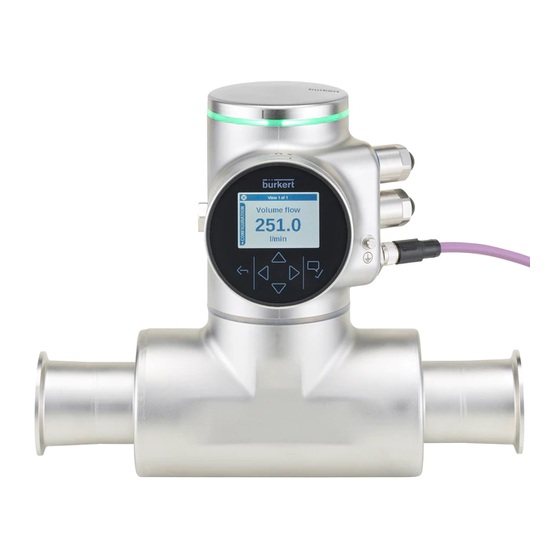
Type 8098 FLOWave L Description DESCRIPTION Device variants The Type 8098 FLOWave L flowmeter is made up of a Type SE98 transmitter and a Type S097 flow sensor. The following pictures describe the main device variants of the Type 8098 FLOWave L flowmeter: • Fig. 1 describes a device with two M20x1.5 cable glands in stainless steel (or in nickel plated brass) and one 5-pin M12 male connector. • Fig. 2 describes the Ethernet device variant, i.e. a device with two 4-pin M12 female connectors and one 5-pin M12 male connector. Blind cover or display module (Type ME31) Device status indicator, seal Transmitter housing, including the electronic modules Type SE98 transmitter M20x1,5 cable glands in nickel... - Page 14 Type 8098 FLOWave L Description Blind cover or display module (Type ME31) Device status indicator, seal Transmitter housing, including the electronic modules Type SE98 transmitter Seal 4-pin M12 female connectors with screwed plugs 5-pin M12 male connector, with screwed plug Functional earth Blind cover Seal Process connection Type S097 flow sensor Sensor measurement tube...
-
Page 15: Wi-Fi Module
• Android with Google: Chrome, from version 53. • Apple: Safari, from iOS 9.3.5. → For more informations about the Wi-Fi module, refer to the Software manual ME31 | WLAN module, available at country.burkert.com. Unlocking magnetic key The device is delivered with a magnetic key to unlock the display module, the Wi-Fi module or the blind cover. -
Page 16: Type Labels
Type 8098 FLOWave L Description Type labels 5.4.1 Adhesive labels 8098 FLOWave L Supply: 12-35 5W Max. IP65 / IP67 / NEMA4X Ambient Temp : -10 to 70°C CAN_H 88888888 SN 9999 CAN_L CAN shield W49MN Made in France 28-06 1. Supply voltage 8. - Page 17 Type 8098 FLOWave L Description 8098 FLOWave L IP65 / IP67 / NEMA 4X Ambient temp.: -10 to 55°C 88888888 SN 9999 CAN_H CAN_L CAN shield W49MN Made in France 28-06 1. IP-Code, NEMA protection type 7. Conformity marking 2. Type of the device 8. Article number 3.
-
Page 18: Laser Marking
Type 8098 FLOWave L Description 5.4.2 Laser marking Supply: 12...35V 5W Max. IP65 | IP67 | NEMA4X Ambient Temp: -10°...+70°C Type: 8098 FLOWave L ID:00xxxxxx | S/N:001234 Slot5: Slot4: W49MN Slot3: Slot2: Slot1: 28-06 Measuring CRN 0C21751.5 Equipment N°E237737 1. Type of the device 8. -
Page 19: Marking Of The Unique Serial Number (Usn)
Type 8098 FLOWave L Description Marking of the Unique Serial Number (USN) The USN is marked on the side of the sensor. The USN is built with the device article number and the device serial number. Device status indicator The device status indicator changes its colour based on the NAMUR NE 107 recommendation. The color of the device status indicator gives the following pieces of information: • Whether device diagnostics are active on not. • If device diagnostics are active, then the device status indicator shows whether diagnostics events have been generated or not. If several diagnostics events have been generated, then the device status indicator shows the diagnostics event with the highest priority. -
Page 20: Technical Data
• Unused cable glands must be sealed with the blind plugs provided. The blind plugs are mounted upon delivery of the device. • Unused M12 connectors must be protected by a screwed plug. not evaluated by UL; only IP64 is evaluated by the ATEX / IECEx notified/certification body. → For the special operating conditions of devices with ATEX / IECEx certification, refer to the ATEX / IECEx supplement for the device. The supplement is available at country.burkert.com. English... -
Page 21: Conformity To Standards And Directives
Type 8098 FLOWave L Technical data Conformity to standards and directives The applied standards, which verify conformity with the EU Directives, can be found on the EU Type Exami- nation Certificate and/or the EU Declaration of Conformity (if applicable). 6.2.1 Conformity to the Pressure Equipment Directive ▶ Make sure that the device materials are compatible with the liquid. ▶ Make sure that the pipe DN is adapted for the device. ▶ Observe the liquid nominal pressure (PN) for the device. The nominal pressure (PN) is given by the device manufacturer. The device conforms to Article 4, Paragraph 1 of the Pressure Equipment Directive 2014/68/EU under the following conditions: • Device used on a pipe (PS = maximum admissible pressure, in bar; DN = nominal dimension of the pipe, no unit) Type of liquid Conditions... -
Page 22: Ehedg Certification
→ To make sure you use EHEDG-compliant gaskets, refer to the "EHEDG Position Paper" available on the EHEDG website. The manufacturer of the device does not supply any gaskets for the process connections. 6.2.4 ATEX / IECEx certification → Refer to the ATEX / IECEx supplement for the device. The supplement is available at country. burkert.com. English... -
Page 23: Liquid Data
Type 8098 FLOWave L Technical data Liquid data °C Ambient temperature Temperatures authorized for a limited duration °C Liquid temperature Fig. 9: Dependency between the liquid temperature and the ambient temperature, device variant with two M20x1.5 cable glands and one 5-pin M12 male connector °C Ambient temperature Temperatures authorized for a limited duration °C... - Page 24 Type 8098 FLOWave L Technical data Table 2: Liquid pressure, depending on the pipe diameter, the type of process connections and the process connection standard Size of the process Type of process Standards the process connections connection connection conform to • DIN 11864-3 series B clamp • DIN 32676 series A PN25 DN08, DN15, DN25 • DIN 32676 series B flange DIN 11864-2 series B PN25 clamp DIN 11864-3 series A PN25...
-
Page 25: Measurement Data
Type 8098 FLOWave L Technical data Measurement data 6.4.1 Volume flow rate Table 3: Volume flow rate measurement • Measurement range • 0...1.7 m /h to 0...200 m /h, depending on the DN of the sensor • Measurement deviation for a volume flow • ±0.4 % of the measured value 1) 2) rate between 10 % of the full scale and the full scale • Measurement deviation for a volume flow • < ±0.08 % of the full scale 1) 2) rate between 1 % of the full scale and 10 % of the full scale •... -
Page 26: Acoustic Transmission Factor
Type 8098 FLOWave L Technical data 6.4.4 Acoustic transmission factor Table 6: Acoustic transmission factor measurement (optional feature) • Measurement range • 10 %...120 % • Resolution • 0.01 % • Repeatability • ±2 % of the measured value • Refresh time • Adjustable. 6.4.5 Density Table 7: Density measurement (optional feature) •... -
Page 27: Electrical Data
Type 8098 FLOWave L Technical data Electrical data Voltage not allowed Ambient temperature °C Temperature authorized for a limited duration Supply voltage V DC Liquid temperature °C Fig. 11: Minimum supply voltage depending on the ambient temperature and the liquid temperature, device variant with two M20x1.5 cable glands and one 5-pin M12 male connector Voltage not allowed Ambient temperature °C Temperature authorized for a limited duration Supply voltage V DC... - Page 28 Type 8098 FLOWave L Technical data Operating voltage • 12...35 V DC; the minimum voltage to be supplied depends on the liquid temperature and on the ambient operating temperature: depending on your device variant, see Fig. 11 or Fig. 12 • Current consumption: max. 2 A • Filtered and regulated • Tolerance: ±10 % • The device must be connected permanently to a Safety Extra-Low Voltage circuit (SELV circuit).
-
Page 29: Mechanical Data
Type 8098 FLOWave L Technical data Mechanical data Dimensions and weight of the device: refer to the technical data sheet regarding Type 8098 FLOWave L available at country.burkert.com Table 9: Materials in contact with ambient air Component Material Transmitter housing Stainless steel 304 / 1.4301, outer surface finish Ra < 1.6 µm Stainless steel 304 / 1.4301, outer surface finish Ra < 1.6 µm Sensor housing (depending on the device variant) Stainless steel 316L / 1.4435, outer surface finish Ra < 1.6 µm Stainless steel / PA6 / TPE Cable glands / Blind plugs / Sealing Nickel plated brass / Black polyoxymethylene (POM) / HNBR (depending on the device variant) and TPE 5-pin M12 male connector / Screwed Stainless steel / Stainless steel / NBR plug / Sealing Nickel plated brass / Nickel plated brass / NBR (depending on the device variant) 4-pin M12 female connector / Screwed... -
Page 30: Installation In A Pipe
Type 8098 FLOWave L Installation in a pipe INSTALLATION IN A PIPE Safety instructions DANGER Risk of injury due to electrical voltage. ▶ Before carrying out work on the system, disconnect the electrical power for all the conductors and isolate it. ▶ In accordance with standard UL/EN 61010-1, all equipment connected to the Type 8098 FLOWave L flowmeter shall be double insulated with respect to the mains and all circuits connected to the Type 8098 FLOWave L flowmeter must be limited energy circuits. ▶ Observe all applicable accident protection and safety regulations for electrical equipment. Risk of injury due to pressure in the installation. -
Page 31: Additional Documentation
Risk of failure or risk of accelerated ageing of electrical components. ▶ Observe the dependence between liquid temperature and ambient temperature (see Fig. 9 and Fig. 10). Additional documentation → If the device is an ATEX / IECEx device variant, then refer to the ATEX / IECEx supplement for Type 8098 FLOWave L available on the internet at country.burkert.com. Preparing the device before installation into the pipe The device is delivered as described in chapter 5.1. Before installing the device into the pipe, you may: • change the position of the transmitter on the sensor. Refer to chapter 7.3.1. - Page 32 Type 8098 FLOWave L Installation in a pipe Fig. 13: Possible positions of the transmitter SE98 → To change the position of the transmitter, do the following: For safety reasons and to comply with standard UL 61010-1, the blind cover and the display module or the Wi-Fi module are locked. → Prepare the unlocking magnetic key, which is delivered with the device, to change the position The blind cover, the display module or of the transmitter.
- Page 33 Type 8098 FLOWave L Installation in a pipe Carefully lift the display module or the Wi-Fi module because a cable connects the display module or the Wi-Fi module to the transmitter. 4. Push the tab of the cable connector to dis- connect the display module or the Wi-Fi module from the transmitter.
- Page 34 Type 8098 FLOWave L Installation in a pipe Lift the transmitter carefully because a cable connects the transmitter to the flow sensor. 9. If the seal is damaged, replace it. Apply a layer of lithium soap grease to the new seal before you put it in place. 10. I f the seal is not located in the groove, put it back in the groove. Seal not in the Seal in the groove: groove: NOT correct correct 11.
-
Page 35: Switching Positions Of The Blind Cover And The Display Module Or The Wi-Fi Module
Type 8098 FLOWave L Installation in a pipe 14. Screw the transmitter clockwise on the flow sensor until the blind cover is perfectly parallel or perpendicular to the axis of the pipe. 15. Fasten the screw with a size 3 hexagonal key to a tightening torque of 1.3 Nm ±0.5 Nm (0.9 ft·lbf ±0.4 ft·lbf) 16. Connect the display module or the Wi-Fi module to the transmitter. 17. Put the mark of the cover on the unlocked marking of the housing and screw the cover clockwise on the transmitter housing until the mark is on the locked position. - Page 36 Type 8098 FLOWave L Installation in a pipe For safety reasons and to comply with standard UL 61010-1, the blind cover and the display module or the Wi-Fi module are locked. → Prepare the unlocking magnetic key, which is delivered with the device. The blind cover, the display module or the Wi-Fi module is locked 1.
- Page 37 Type 8098 FLOWave L Installation in a pipe 6. Put the magnetic key on the mark related to the blind cover. You should hear a click indi- cating that the blind cover is unlocked. Do not use a tool to turn the blind cover. 7.
-
Page 38: Recommendations For The Installation Into The Pipe
→ Always install a heavy device with the help of another person and with the use of appropriate tools. → If the liquid temperature is subject to variations, make sure that the device can expand freely. → Make sure the DN of the measurement tube is suited to the flow velocity: refer to the data sheet of the device, available at country.burkert.com. The device is not intended to measure the flow rate of liquids if gas bubbles are present, whatever the origin of the bubbles (air intake, cavitation, degassing…). → Choose a location with enough free space to put the magnetic key on the symbol at the side of the device. - Page 39 Type 8098 FLOWave L Installation in a pipe → To make sure that neither air bubbles nor gas bubbles trouble the measuring, install the device as rec- ommended in Fig. 15. flow direction α flow direction Recommended Not recommended Not recommended α is the minimum angle to the horizontal for proper self-draining (see Table 12) Fig. 15: Orientation of a device to avoid air bubbles and gas bubbles →...
- Page 40 Type 8098 FLOWave L Installation in a pipe No pipe insulation Pipe insulation Fig. 16: Thermal insulation of the pipe → To make sure the internal temperature of the transmitter with cable glands does not exceed the authorized maximum value, install the device as recommended in Fig. 17. → To make sure the internal temperature of the transmitter does not exceed the authorized maximum value, install an Ethernet device variant as recommended in Fig. 18. Recommended Not recommended Recommended These orientations are valid for all the positions of the Type SE98 transmitter on the Type S097 flow sensor. Refer to Fig. 13: Possible positions of the transmitter SE98, page 32 Fig. 17: Orientation of a device variant with cable glands to avoid effects of high liquid temperatures...
-
Page 41: Installing The Device Into The Pipe
Type 8098 FLOWave L Installation in a pipe Installing the device into the pipe CAUTION Risk of injury due to a heavy device. A heavy device can fall down during transport or during installation and cause injuries. ▶ Transport, install and dismantle a heavy device with the help of another person. ▶... -
Page 42: Installing A Device With External-Threaded Connections According To Din 11851 Series A For Pipes According To Din 11850
• 2 round slotted nuts • 2 conical ferrules • 2 gaskets that respect the standard DIN 11851. If the installation must be EHEDG-compliant, then supply EHEDG-compliant gaskets. For an EHEDG-compliant use, Burkert recommends gaskets of one of the fol- lowing type: - ASEPTO-STAR k-flex upgrade gaskets from Kieselmann GmbH, Germany, - SKS gaskets set DIN 11851 EHEDG with EPDM or FKM inner gasket from Siersema Komponenten Service (S.K.S.) B.V., Netherlands... -
Page 43: Electrical Installation
Type 8098 FLOWave L Electrical installation ELECTRICAL INSTALLATION Safety instructions DANGER Risk of injury due to electrical voltage. ▶ Before carrying out work on the system, disconnect the electrical power for all the conductors and isolate it. ▶ In accordance with standard UL/EN 61010-1, all equipment connected to the Type 8098 FLOWave L flowmeter shall be double insulated with respect to the mains and all circuits connected to the Type 8098 FLOWave L flowmeter must be limited energy circuits. ▶ Observe all applicable accident protection and safety regulations for electrical equipment. Risk of injury due to pressure in the installation. - Page 44 Type 8098 FLOWave L Electrical installation WARNING Risk of injury due to unintentional switch on of the power supply or uncontrolled restart of the installation. ▶ Take appropriate measures to avoid unintentional activation of the installation. ▶ Guarantee a set or controlled process restart after carrying out any intervention on the device. CAUTION Risk of injury due to a heavy device. A heavy device can fall down during transport or during installation and cause injuries. ▶...
-
Page 45: Additional Documentation
To do the electrical installation of a device with two 4-pin M12 female connectors (Ethernet device variant) that is connected to an Ethernet network, observe standard ISO / IEC 61918. Additional documentation • For more information on büS, read the cabling guide available in English and in Japanese (Cabling_guide_for_büS/EDIP.pdf) at country.burkert.com. • For more information on CANopen that is related to the device, refer to the Operating Instructions "CANopen Network configuration" at country.burkert.com. • If the device is an an ATEX / IECEx device variant, then refer to the ATEX / IECEx supplement for Type 8098 FLOWave L available on the internet at country.burkert.com. -
Page 46: Connecting The Device To A Büs / Canopen Network
Type 8098 FLOWave L Electrical installation Voltage not allowed Ambient temperature °C Temperature authorized for a limited duration Supply voltage V DC Liquid temperature °C Fig. 21: Minimum supply voltage depending on the ambient temperature and the liquid temperature, device variant with two 4-pin M12 female connectors and one 5-pin M12 male connector (Ethernet device variant) Connecting the device to a büS / CANopen network For a correct operation of the device, use a 5-pin M12 female connector in stainless steel with shield con- nection. The büS cable that is available from Bürkert has an external diameter of 8.2 mm. - Page 47 Type 8098 FLOWave L Electrical installation • Pin 1: CAN shield • Pin 2: 12...35 V DC • Pin 3: GND • Pin 4: CAN_H • Pin 5: CAN_L Fig. 22: Pin assignment of the 5-pin M12 male connector Cable and conductors connected inside the device to the 5-pin M12 male connector Fig. 23: Wiring ex works of the 12 push-in terminal strip to the 5-pin M12 male connector English...
-
Page 48: Activating The Device Internal Termination Resistor
Type 8098 FLOWave L Electrical installation Activating the device internal termination resistor The device has an internal termination resistor that can be activated if the device is installed at one end of a büS network or of a CANopen network. If you activate the device internal termination resistor, do not install more than one termination resistor at the same end of the büS network or of the CANopen network. To have an adapted network, connect one termination resistor at each end of the network. →... -
Page 49: Terminal Assignment Of The 12 Push-In Terminal Strip
Type 8098 FLOWave L Electrical installation Terminal assignment of the 12 push-in terminal strip The terminal strip located in the transmitter housing has 12 push-in terminals. Fig. 24: Wiring ex works of the 12 push-in terminal strip → To access the 12 push-in terminal strip, open the front of the transmitter; see chapter 8.9. → If you need to disconnect a conductor, first push the terminal with a slot screwdriver 3.0 mm (any length) and a force of max. 40 N. 1 2 3 4 5 6 7 8 9 1 1 1 2 Orange LED Green LED (device variant with two M20x1,5 cable... -
Page 50: Opening The Front Of The Transmitter
Type 8098 FLOWave L Electrical installation Opening the front of the transmitter To open the front of the transmitter housing, remove either the blind cover or the display module or the Wi-Fi module. Procedure to open the front of the transmitter if the blind cover is on the front of the device 1. Put the magnetic key on the mark related to the blind cover. -
Page 51: Wiring The Device Through The M20X1.5 Cable Glands In Stainless Steel (Device Variant With Cable Glands)
Type 8098 FLOWave L Electrical installation Push the tab to unlock the cable connector Carefully pull the display module or the Wi-Fi module because a cable connects the display module or the Wi-Fi module to the transmitter. 5. Push the tab of the cable connector to dis- connect the display module or the Wi-Fi module from the transmitter. - Page 52 Type 8098 FLOWave L Electrical installation 5. Loosen the nut of the cable gland. 6. Do not remove the nut of a stainless steel M20x1.5 cable gland. The nut of a stainless steel M20x1.5 cable gland cannot be removed. 7. Turn the nut until the stop. If you turn beyond the stop, the cable gland unscrews from the device and the device is no longer tight. 8.
-
Page 53: Wiring The Device Through The M20X1.5 Cable Glands In Nickel Plated Brass (Device Variant With Cable Glands)
Type 8098 FLOWave L Electrical installation 14. Put each conductor in the correct terminal of the terminal strip. 15. To connect the 12...35 V DC power supply through the cable glands, refer to chapter 8.13. 16. To connect the outputs, refer to chapter 8.14 and chapter 8.15. 17. Connect the functional earth conductor. See chapter 8.12. 18. If the display module or the Wi-Fi module is removed, connect it back. 19. Close the front and the top of the transmitter housing. Fig. 28: Wiring the device through the M20x1.5 cable glands in stainless steel 8.11 Wiring the device through the M20x1.5 cable glands in nickel plated brass (device variant with cable glands) - Page 54 Type 8098 FLOWave L Electrical installation 9. If the cable diameter is between 9 and 14 mm, → vertically put a screwdriver between the two seals, → lift the inner seal and remove it. → Put the cable through the cable gland. → Use a size 24 hexagonal key to tighten the cable gland to a torque of 10 Nm (7.4 ft·lbf). 10. A ttach each cable to the functional earth plate. The shield must be in contact with the functional earth plate.
- Page 55 Type 8098 FLOWave L Electrical installation 13. Put each conductor in the correct terminal of the terminal strip. 14. To connect the 12...35 V DC power supply through the cable glands, refer to chapter 8.13. 15. To connect the outputs, refer to chapter 8.14 and chapter 8.15. 16. Connect the functional earth conductor. See chapter 8.12. 17. If the display module or the Wi-Fi module is removed, connect it back. 18. Close the front and the top of the transmitter housing. Fig. 29: Wiring the device through the M20x1.5 cable glands in nickel plated brass English...
-
Page 56: Connecting The Functional Earth (Device Variant With Two M20X1.5 Cable Glands)
Type 8098 FLOWave L Electrical installation 8.12 Connecting the functional earth (device variant with two M20x1.5 cable glands) → For a proper function of device always connect the yellow/green functional earth conductor: - either to the functional earth plate in the transmitter housing (see Fig. 31 in chapter 8.13), - or to the functional earth screw on the outer surface of the transmitter housing (see Fig. 30). If you connect the conductor to the functional earth screw: →... -
Page 57: Connecting The Device To A 12
Type 8098 FLOWave L Electrical installation 8.13 Connecting the device to a 12...35 V DC power supply through the M20x1.5 cable glands (device variant with cable glands) 1. Use a 3.0 mm slot screwdriver (any length) and a force of max. 40 N to push the terminal 5 and dis- connect the white conductor. Do not cut the white conductor. 2. Insulate the white conductor. 3. Connect the power supply as shown in Fig. 31. To connect to the positive 12...35 V DC power supply for the device through a cable gland To connect to the negative power supply for the device... -
Page 58: Wiring Output 1 (Analogue) And Output 3 Configured As An Analogue Output (Device Variant With Cable Glands)
Type 8098 FLOWave L Electrical installation Fig. 32: Device connected to a 12...35 V DC power supply through the M20x1.5 cable glands 8.14 Wiring output 1 (analogue) and output 3 configured as an analogue output (device variant with cable glands) NOTICE Risk of short-circuit if the configuration of output 3 is wrong. ▶ Before wiring output 3 as an analogue output, make sure output 3 is configured as an analogue output in the Parameter menu of the outputs. See chapter 9.8 Changing the type of output 3. An analogue output can be wired either in sourcing mode or in sinking mode. 1 2 3 4 5 6 7 8 9 1 1 2 12-35 V DC 12-35 V DC... -
Page 59: Wiring Output 2 (Digital) And Output 3 Configured As A Digital Output (Device Variant With Cable Glands)
Type 8098 FLOWave L Electrical installation 8.15 Wiring output 2 (digital) and output 3 configured as a digital output (device variant with cable glands) NOTICE Risk of short-circuit if the configuration of output 3 is wrong. ▶ Before wiring output 3 as a digital output, make sure output 3 is configured as a digital output in the Parameter menu of the outputs. See chapter 9.8 Changing the type of output 3. A digital output can be wired either in NPN mode or in PNP mode. Orange LED is lit if the related digital output is switched to ON 1 2 3 4 5 6 7 8 9 1 1 2 12-35 V DC 12-35 V DC Power supply for... -
Page 60: Knowing The Status Of The Ethernet Network (Device Variant With Two 4-Pin M12 Female Connectors - Ethernet Device Variant)
Type 8098 FLOWave L Electrical installation 8.16 Knowing the status of the Ethernet network (device variant with two 4-pin M12 female connectors - Ethernet device variant) The status of the Ethernet network is indicated by LEDs. The LEDs are located on the industrial communi- cation module in the transmitter housing. -
Page 61: Specifications Of The Cables And Conductors For The 4-Pin M12 Female Connectors
Type 8098 FLOWave L Electrical installation 8.17 Specifications of the cables and conductors for the 4-pin M12 female connectors Table 18: Specifications of the cables and conductors for the 4-pin M12 female connectors Specification of the cables and conductors Recommended value Electromagnetic protection (EMC) Shielded conductor with minimum STP Minimum category CAT-5 Maximum length 100 m... -
Page 62: Connecting The Functional Earth (Device Variant With Two 4-Pin M12 Female Con- Nectors - Ethernet Device Variant)
Type 8098 FLOWave L Electrical installation Cable and conductors con- nected inside the device from X1 to the upper 4-pin M12 female connector Cable and conductors con- nected inside the device from X2 to the middle 4-pin M12 female connector Cable and conductors connected inside the device from the 12 push-in terminal strip to the 5-pin M12 male connector... -
Page 63: How To Do The Settings
The menu structure is the same in the display module and in the Bürkert Communicator software. → To do the settings of the device with the Type ME31 display module, refer to the Type 8098 FLOWave L Operating Instructions. → To use the Bürkert Communicator software, first prepare the necessary hardware and the software. Refer to chapter 9.3. Then do the settings as described in the Operating Instructions. → To use some specific functions that are only available with the Bürkert Communicator software, refer to the Type 8920 Operating Instructions, available on the internet at country.burkert.com → To get detailed information on the software of the Type ME31 display module, refer to the related Oper- ating Instructions, available on the internet at country.burkert.com Connect the device to the Bürkert Communicator software To do the settings with the Type 8920 Bürkert Communicator software, do the following steps: 1. - Page 64 Type 8098 FLOWave L How to do the settings 7. Insert the appropriate power adapter into the AC/DC adapter. 8. Connect the cable of the AC/DC adapter to the related connector of the female M12 connector. Termination Female M12 resistance connector büS stick Power adapter Y plug AC/DC adapter mini-USB Cable of the AC/DC adapter Fig. 39: Assembled connection cables, plugs and büS stick 9. Screw the Y plug on the male M12 connector of the device. 10. I nsert the büS stick into a USB port of the PC.
-
Page 65: Display Module: Description Of The User Interface
Type 8098 FLOWave L How to do the settings Display module: description of the user interface For a complete description of the display module, refer to the Type 8098 FLOWave L Operating Instructions, available on the internet at country.burkert.com To get detailed information on the display software, refer to the Operating Instructions of the Type ME31 display software, available on the internet at country.burkert.com The user interface is made up of a display and touch sensitive keys. View 1 of 4 Display Volume flow 30.1 l/min BACK key Navigation keys OK key Fig. 40:... -
Page 66: Changing The Login User Level If The Adjustment Is Not Protected Through Passwords
Installer You can only change to the Bürkert user level. → To change the login user level in the Bürkert Communicator software, refer to the Type 8920 Operating Instructions, available on the internet at country.burkert.com. Do the following to change the login user level on the display module: → Long press, to open the context menu. → Change user level Confirm. -
Page 67: Changing The Login User Level If The Adjustment Is Protected Through Passwords
How to do the settings 9.5.2 Changing the login user level if the adjustment is protected through passwords If the adjustment is protected through passwords, the symbol related to the active user level is displayed in the information bar. → To change the login user level in the Bürkert Communicator software, refer to the Type 8920 Operating Instructions, available on the internet at country.burkert.com. Do the following to change the login user level on the display module: → Long press, to open the context menu. → Change user level Confirm. -
Page 68: Reading Out The Access Path To A Menu Item (Display Module Only)
Type 8098 FLOWave L How to do the settings Reading out the access path to a menu item (display module only) If you are lost in the menu structure, you can display the access path. → Long press, to open the context menu. → Where am I? Confirm. Read out the access path to the displayed menu item. Doing the adjustments when energizing the Quick start device for the first time (display module only) When the device is energized for the first time, the user is guided to make the following mandatory settings:... -
Page 69: Changing The Type Of Output 3
Type 8098 FLOWave L How to do the settings Changing the type of output 3 NOTICE Risk of short-circuit if the configuration of output 3 is wrong. ▶ Before wiring the output 3, make sure the output 3 is correctly configured. The output parameters can be set with the Installer user level. Even if the menu Outputs is available on an Ethernet device variant, we recommend to not use the outputs. -
Page 70: Commissioning
First commissioning for measuring the flow rate or for filling containers To find detailled information on the settings, search the highlighted term in the Type 8098 FLOWave L Operating Instructions available at country.burkert.com. 1. Energise the device. 2. Connect the device to the Bürkert Communicator software. Print a pdf report of all the current settings of the device. Select the process values that you want to monitor graphically. Refer to the Type 8920 Oper- ating Instructions, available on the internet at country.burkert.com... -
Page 71: First Commissioning For Detecting A Change Of Liquid In The Pipe
First commissioning for detecting a change of liquid in the pipe To find detailled information on the settings, search the highlighted term in the Type 8098 FLOWave L Operating Instructions available at country.burkert.com. 1. Energise the device. 2. Connect the device to the Bürkert Communicator software. Print a pdf report of all the current settings of the device. Select the process values that you want to monitor graphically. Refer to the Type 8920 Oper- ating Instructions, available on the internet at country.burkert.com. - Page 72 Type 8098 FLOWave L Commissioning 6. If the liquid is not water, then read out the value of the parameter DF. • If the value is between 0.8 and 1.2, then the flow rate of the liquid can be measured by the device. • If the value is lower than 0.8 or higher than 1.2, then the flow rate of the liquid might not be measured accurately by the device. 7. Set the parameter Viscosity compensation for the liquid: • If the liquid is water, then make sure that the parameter Viscosity compensation is set to water. • If the liquid has a kinematic viscosity that is between 0.5 and 2 mm /s, then you can keep the parameter to water. Viscosity compensation • If the liquid is not water or if the liquid kinematic viscosity is lower than 0.5 or higher than 2 mm /s, then set the parameter to a value that is adapted to the liquid properties and to the Viscosity compensation process conditions.
-
Page 73: First Commissioning For Detecting Bubbles In The Pipe
19. Disconnect the Bürkert Communicator software from the device. 10.5 First commissioning for detecting bubbles in the pipe To find detailled information on the settings, search the highlighted term in the Type 8098 FLOWave L Operating Instructions available at country.burkert.com. 1. Energise the device. 2. Connect the device to the Bürkert Communicator software. Print a pdf report of all the current settings of the device. Select the process values that you want to monitor graphically. Refer to the Type 8920 Oper- ating Instructions, available on the internet at country.burkert.com. -
Page 74: Maintenance And Troubleshooting
Type 8098 FLOWave L Maintenance and troubleshooting MAINTENANCE AND TROUBLESHOOTING 11.1 Safety instructions Risk of injury due to electrical voltage. ▶ Before carrying out work on the system, disconnect the electrical power for all the conductors and isolate it. ▶ In accordance with standard UL/EN 61010-1, all equipment connected to the Type 8098 FLOWave L flowmeter shall be double insulated with respect to the mains and all circuits connected to the Type 8098 FLOWave L flowmeter must be limited energy circuits. ▶ Observe all applicable accident protection and safety regulations for electrical equipment. Risk of injury due to pressure in the installation. -
Page 75: Information On Returning The Device To The Manufacturer Or To The Reseller
→ To return the device for calibration or any after sales service, use the original packaging. → Send the device back to your local Bürkert sales office. The addresses of our international sales offices are available on the internet at country.burkert.com. 11.3 Cleaning the outer surface of the device • Always use a cleaning agent compatible with the materials from which the device is made. -
Page 76: Troubleshooting When A Message Is Displayed
Type 8098 FLOWave L Maintenance and troubleshooting 11.5 Troubleshooting when a message is displayed → If the message displayed on your device is not explained in the Operating Instructions, contact Bürkert. If a message has been generated: • a symbol is displayed in the information bar: see Table 20. • Ex works and if the status indicator is not switched off, the device status indicator changes its colour and state based on the NAMUR NE 107 recommendation: see chapter 5.8. • The message is displayed in a list called Messages overview. The list can be accessed via the context menu. See chapter 9.5.1. Table 20: Device status symbols Symbol... -
Page 77: Spare Parts And Accessories
Type 8098 FLOWave L Spare parts and accessories SPARE PARTS AND ACCESSORIES CAUTION Risk of injury and/or damage caused by the use of unsuitable parts. Incorrect accessories and unsuitable replacement parts may cause injuries and damage the device and the surrounding area. ▶ Use only original accessories and original replacement parts from Bürkert. Spare part or accessory Article number Unlocking magnetic key 690309 5-pin M12 female and 5-pin M12 male straight cable plugs, moulded at each end of 772 404 a 1 m shielded cable... -
Page 78: Packaging, Transport
Type 8098 FLOWave L Packaging, Transport PACKAGING, TRANSPORT CAUTION Risk of injury due to a heavy device. A heavy device can fall down during transport or during installation and cause injuries. ▶ Transport, install and dismantle a heavy device with the help of another person. ▶ Use appropriate tools. NOTICE Damage due to transport Transport may damage an insufficiently protected device. - Page 80 www.burkert.com...
Need help?
Do you have a question about the FLOWave L 8098 and is the answer not in the manual?
Questions and answers