
Related Manuals for Burkert 8098 FLOWave S


Summary of Contents for Burkert 8098 FLOWave S
- Page 1 Type 8098 FLOWave S Durchflussmesser Flowmeter Débitmètre Quickstart English Deutsch Français...
- Page 2 We reserve the right to make technical changes without notice. Technische Änderungen vorbehalten. Sous réserve de modifications techniques. © Bürkert Werke GmbH & Co. KG, 2019 – 2022 Operating Instructions 2205/05_EU-ML_00815331 / Original EN...
-
Page 3: Table Of Contents
Type 8098 Table of contents ELECTRICAL INSTALLATION ..........22 ABOUT THESE INSTRUCTIONS .......... 4 8.1 Safety instructions ............. 22 Symbols ............... 4 8.2 Requirements for electrical installation ..... 23 1.2 Definition of terms ............4 8.3 Additional documentation ......... 23 INTENDED USE ..............5 8.4 Connecting the device ..........23 Device with ATEX/IECEx approval ....... -
Page 4: About These Instructions
▶ Failure to observe the warning may result in damage to the ▶ Observe in particular the safety instructions, intended use and device or system. operating conditions. ▶ Persons, who work on the device, must read and understand Indicates important additional information, tips and these instructions. recommendations. The operating instructions can be found on the Internet at: Refers to information in these instructions or in other country.burkert.com documentation. Symbols ▶ Designates an instruction to prevent risks. → designates a procedure that must be carried out. DANGER! Indicates a result. Warns of an immediate danger. ▶ Failure to observe the warning may result in a fatal or serious Definition of terms injury. -
Page 5: Intended Use
Risk of explosion in the event of improper use of the device in potentially explosive atmospheres. - clean liquids ▶ Observe the specifications of the ATEX/IECEx-conformity - non emulsified liquids (homogeneous liquids) certificate. - liquids that are free of air bubbles ▶ Observe the specifications given in the ATEX/IECEx supple- - liquids that are free of gas bubbles ment for Type 8098 FLOWave S. The supplement is available - liquids that are free of solids. country.burkert.com ▶ Use the device for its intended purpose only. Non-intended use of the device may be dangerous to people, nearby equipment and the environment. The ATEX/IECEx approval is only valid if the device is used as described in the ATEX/IECEx supplement. ▶ Correct transportation, correct storage as well as correct instal- lation, commissioning, operation and maintenance are essential If unauthorized changes are made to the device, then the ATEX/ for reliable and problem-free operation. IECEx approval becomes invalid. -
Page 6: Basic Safety Instructions
Type 8098 Basic safety instructions BASIC SAFETY INSTRUCTIONS CAUTION! These safety instructions do not consider any contingencies or inci- Risk of injury due to a heavy device. dents which occur during installation, operation and maintenance. A heavy device can fall down during transport or during instal- The operator is responsible for observing the location-specific safety lation and cause injuries. regulations, also with reference to the personnel. ▶ Transport, install and dismantle a heavy device with the help of another person. DANGER! ▶ Use appropriate tools. Risk of injury from high pressure and discharge of medium. To prevent injury, ensure the following: ▶... -
Page 7: General Information
Rue du Giessen components. In the worst case scenario, they will be destroyed BP 21 immediately or will fail after start-up. F-67220 TRIEMBACH-AU-VAL ▶ Observe the requirements in accordance with EN 61340-5-1 to minimize or avoid the possibility of damage caused by sudden International electrostatic discharge. Contact addresses can be found on the final pages of the printed ▶ Also ensure that you do not touch electronic components when the power supply voltage is present. operating instructions. And also on the Internet at: Damage to the device caused by the wrong medium. ▶ Check the chemical compatibility of the materials in contact country.burkert.com with the medium. Warranty The warranty is only valid if the device is used as intended in accor- dance with the specified application conditions. Information on the internet The operating instructions and data sheets for Type 8098 can be found on the Internet at: country.burkert.com english... -
Page 8: Structure
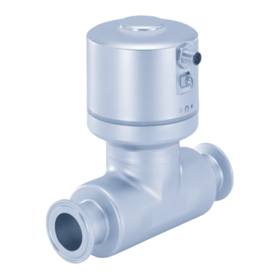
Type 8098 Structure STRUCTURE TECHNICAL DATA Operating conditions Status indicator and seal Ambient temperature −10 °C...+70 °C Electrical connection Air humidity < 85 %, non condensing Grounding connection Operating altitude Up to 2000 m above sea level (protective earth) Transmitter Operating mode Continuous operation Seal Device mobility Fixed device Sensor housing Use I ndoor and outdoor (with pro- Process connection tection against electromagnetic interference, ultraviolet rays and weather conditions) Fig. 1: Structure Installation category C ategory I according to UL/ The flowmeter Type 8098 FLOWave S is made up of a transmitter EN 61010-1 Type SE91 and a flow sensor Type S097. -
Page 9: Conformity
Type 8098 Technical data Conformity 6.3.2 UL certification The devices with variable key PU01 or PU02 are UL-certified devices In accordance with the EU Declaration of conformity, the device and comply with the following standards: is compliant with the EU Directives. • UL 61010-1 Standards and directives • CAN/CSA-C22.2 n°61010-1 The applied standards, which verify conformity with the EU Directives, can be found on the EU-Type Examination Certificate Identification on the Certification Variable key and / or the EU Declaration of Conformity. device UL recognized PU01 6.3.1 Conformity to the Pressure Equipment Directive Measuring The device conforms to Article 4, Paragraph 1 of the Pressure UL listed PU02 Equipment ®... -
Page 10: Type Label, Adhesive Label
Type 8098 Technical data Type label, adhesive label Process connections Diameters Clamp connections according DN08, DN15 (except variants to DIN 32676 series B with a clamp diameter of 8098 FLOWave S Supply: 12-35 2.5W Max. 34.0 mm) DN25, DN40, IP65 / IP67 / NEMA4X Ambient Temp : -10 to 70°C DN50, DN65, DN80 Clamp connections according DN10, DN15, DN25, DN40, CAN_H 88888888 SN 999999 to DIN 32676 series A DN50, DN65, DN80 CAN_L CAN shield Clamp connections according DN08, DN15, DN25, DN40, W49MN 28-06 Made in France 28-06 to DIN 11864-3 series A,... -
Page 11: Type Label Lasered
Type 8098 Technical data Type label lasered CAN_H S097 FLOWave Flow sensor CAN_L Type: 8098 FLOWave S Pipe: 316L/1.4435 Housing: 304/1.4301 CAN shield 5 pole M12 DIN 11866 C / Clamp D50.5 DIN 32676 B DN15 ID: 00571790 | S/N: 001000 PN25bar Max. flow:10 m3/h W4ZAL Temp. -
Page 12: Certification Markings
Type 8098 Technical data Liquid data Ambient temperature °C Temperatures Fig. 6: Type label flow sensor (example) authorized for a limited duration 1. Type 2. Material of the pipe and material of the housing 3. Standard the pipe conforms to type and standard of the process connection conforms to DN of the measurement tube °C 4. Pressure class of the device and maximum flow rate Liquid temperature 5. Liquid temperature range 6. Manufacture code Fig. 7: Dependency between the liquid temperature and the ambient temperature Liquid temperature − 20 °C...+110 °C, with clamp process Certification markings connections. Up to 140 °C for maximum Certification markings are either located on the Type label of the 60 minutes for a sterilisation process. - Page 13 Type 8098 Technical data Speed of sound in the liquid Process connection DN08, 3/8", 1/2" 1000...2000 m/s Size Type Standards ≥ DN15, ≥ 3/4" 800...2300 m/s DN50 clamp DIN 11864-3 series A PN16 Process connection DIN 11864-3 series B DIN 32676 series A Size Type Standards DIN 32676 series B DN08, clamp DIN 11864-3 series B PN25 SMS 3017 / ISO 2852 for DN10, DIN 32676 series A pipes according to SMS 3008 DN15, DIN 32676 series B flange DIN 11864-2 series A PN16 DN25 flange DIN 11864-2 series B PN25...
-
Page 14: 6.10 Measurement Data
Type 8098 Technical data 6.10 Measurement data 6.10.2 Temperature Measurement range −20 °C...+140 °C 6.10.1 Volume flow rate Measurement deviation ±1 °C Measurement range 0...1.7 m /h to temperatures up to 100 °C 0...200 m Measurement deviation ±1.5 % depending on the temperatures between 100 °C DN of the sensor and 140 °C Measurement deviation for a volume ±0.4 % of the 1) 2) Refresh time 1 s flow rate between 10 % of the full scale measured value and the full scale Tab. 6: Temperature measurement Measurement deviation... - Page 15 Type 8098 Technical data 6.10.6 Mass flow rate 6.10.4 Acoustic transmission factor Measurement range 0...1360 kg/h to Measurement range 10 %...120 % 0...260000 kg/h, Resolution 0.01 % depending on the DN of the sensor Repeatability ±2 % of the measured value Measurement deviation for a mass ±2.4 % of the mea- 1) 2) flow rate between 10 % of the full scale sured value Refresh time Adjustable (Bürkert Communicator) and the full scale of volume flow rate Measurement deviation for a mass ±2.08 % of the full 1) 2) Tab. 8: Acoustic transmission factor measurement (optional feature) flow rate between 10 % of the full scale...
-
Page 16: Electrical Data
Type 8098 Technical data 6.11 Electrical data Filtered and regulated Extra-Low Voltage circuit (SELV circuit) Voltage not allowed Limited Power Source (LPS) according to standards Temperature authorized for a limited duration UL/EN 60950-1 or through a limited-energy circuit according to standards UL/EN 61010-1 Ambient temperature °C Operating voltage V DC Current consumption max. 1 A Power consumption without outputs ≤ 2.5 W ≤ 5 W with outputs Polarity reversal Protected Outputs (variant) C onfigurable as analogue output or digital output Analog output 4 ...20 mA current 3.6 mA or 22 mA to indicate an error Uncertainty: ±0.04 mA Resolution: 0.8 μA Liquid temperature °C Open loop detection (diagnostics software function) Sink or source mode Fig. 8: Minimum supply voltage depending on the ambient temperature... -
Page 17: 6.12 Mechanical Data
Type 8098 Technical data 0...2000 Hz, 5...35 V DC, max. 700 mA 5-pin M12 male Galvanically isolated, passive connector Stainless steel Overload information (diagnostics software function) Blind plug Stainless steel Protected against overloads and polarity reversals Seals Communications Sensor/transmitter Silicone interface Transmitter/status indicator EPDM C onnection to PC via USB-büS interface (see chapter 12 Accessories) Type label (adhesive labels) Polyester T he büS connection of the variant with outputs is Sensor measurement tube S tainless steel 316L / DIN 1.4435 only for connection to the Bürkert Communicator for configuration and software updating of the device. Line connections S tainless steel 316L / DIN 1.4435 Due to the lack of CAN shielding, conventional büS/ Surface finish CANopen communication is not recommended. according to ISO 4288 Communication Measurement tube... -
Page 18: Installation
Type 8098 Installation INSTALLATION CAUTION! Safety instructions Risk of injury due to a heavy device. DANGER! A heavy device can fall down during transport or during instal- lation and cause injuries. Risk of injury from high pressure in the equipment/device. ▶ Transport, install and dismantle a heavy device with the help ▶ Before working on equipment or device, switch off the pressure of another person. and deaerate/drain lines. ▶ Use appropriate tools. ▶ Respect the regulations to the use of dangerous liquids. Risk of injury from electric shock. Preparatory work ▶... -
Page 19: Recommendations For The Installation Into The Pipe
Recommendations for the installation → If the seal is damaged, replace into the pipe it. Apply a layer of lithium soap → Protect this device against electromagnetic interference, ultra- grease to the new seal before violet rays and, when installed outdoors, the effects of climatic you put it in place. conditions. → If the seal is not located in → Make sure the DN of the measurement tube is suited to the the groove, put it back in the flow velocity: refer to the data sheet of the device, available at groove. country.burkert.com. english... - Page 20 Type 8098 Installation → Choose a location with enough free space to put the magnetic Process connection Angle against the key on the symbol at the side of the device. horizontal Type Standards → For heavy devices or long pipes, support the device and pipes. DN15 to DN50: DIN 32676 series A → Transport and install a heavy device with the help of another minimum 5° DIN 11864-3 series A clamp person and suitable tools. SMS 3017 / ISO 2852 for DN8 and DN65 to DN100: pipes according to SMS 3008 → If the temperature of the liquid is subject to fluctuations, minimum 3° ensure that the device can expand. DN15 to DN50: → Install the device upstream a valve or any equipment that minimum 5° flange DIN 11864-2 series A changes the pipe diameter or the pipe direction. DN8 and DN65 to DN100: minimum 3° Under reference conditions i.e. measuring liquid = water free ASME BPE from gas bubbles and solids, ambient and water temperature =...
-
Page 21: Installing The Device Into The Pipe
Type 8098 Installation Installation: → To make sure the internal temperature of the transmitter does not exceed the authorized maximum value, install the device → Make sure that the seals are in good condition. as recommended in Fig. 11. → Place seals adapted to the process (temperature, liquid type) in the grooves of the clamp connections. → Attach the clamp connections to the pipe with clamp collars. Make sure that tightening the clamp collar does not create bulges at the gaskets. 7.4.2 Installing a device with flange connections Not recommended Recommended The flange connections according to DIN 11864-2 series A, B and C are hygienic connections. → Use any seals that are adapted to the process. 1) These orientations are valid for all the positions of the transmitter on the flow sensor. -
Page 22: Electrical Installation
Type 8098 Electrical installation ELECTRICAL INSTALLATION For EHEDG conformity and threaded connections according to DIN 11851 Series A for pipes to DIN 11850: Safety instructions → Only use EHEDG-compliant gaskets: ASEPTO-STAR K-flex Upgrade gaskets from Kieselmann DANGER! GmbH, Germany or S.K.S. gasket set DIN 11851 EHEDG with EPDM or FKM Risk of injury from high pressure in the equipment/device. inner gasket from Siersema Komponenten Service (S.K.S.) ▶ Before working on equipment or device, switch off the pressure B.V., Netherlands and deaerate/drain lines. Installation: ▶ Respect the regulations to the use of dangerous liquids. Risk of injury from electric shock. Gasket ▶... -
Page 23: Requirements For Electrical Installation
Type 8098 from the mains. A heavy device can fall down during transport or during instal- → All circuits connected to the flow meter Type 8098 lation and cause injuries. must be limited energy circuits. ▶ Transport, install and dismantle a heavy device with the help of another person. Additional documentation ▶ Use appropriate tools. Further information on büS can be found in the cabling guide for büS/EDIP at country.burkert.com under the type. Requirements for electrical installation Further information on CANopen, which refers to the device, can be found in the operating manual “CANopen Network Configu- WARNING! ration” at country.burkert.com. Risk of injury from improper installation. ▶ Install the circuit breaker or the switch in an easily accessible Connecting the device place. Pin assignment for variant without outputs: ▶... - Page 24 Type 8098 Electrical installation Pin assignment for variant with outputs: Output 1 Connection to supply voltage, communication and outputs: Output 1 as Pin 5 Pin 6 Pin 1: +24 V DC (12...35 V DC) analogue output (as sink or Pin 2: GND + – – source) 12...35 V DC Pin 3: CAN_L 4...20 mA input at Supply voltage Pin 4: CAN_H external instrument Pin 5: AO/DO – (output 1) Output 1 as Pin 6 Pin 5 Pin 6: AO/DO + (output 1) digital output (as Pin 7: AO/DO – (output 2) NPN or PNP) –...
- Page 25 Type 8098 Electrical installation Connect the device: Voltage not allowed → Use pre-assembled connection cable. Temperature authorized for a limited duration → Connect the M12 socket to the device and tighten Ambient temperature °C Operating voltage V DC (max. 0.6 Nm). → Observe minimum supply voltage, see Fig. 15. → Connect protective earth (see chapter 8.5). → If the device is connected to a büS network or to a CANopen network and at one end of the büS network or of the CANopen network, either install a one or two 120 Ω termination resistors in the line or activate the device internal termination resistorwith software: see chapter “Activating the device internal terminating resistor” in the operating instructions. The büS or CANopen line must be adapted to 60 Ω. The minimum voltage to be supplied depends on the liquid tem- perature and on the ambient operating temperature. Liquid temperature °C Fig. 15: Minimum supply voltage depending on the ambient temperature and the liquid temperature english...
-
Page 26: Connecting The Protective Earth
Type 8098 Start-up Connecting the protective earth START-UP For proper function of the device, connect the yellow/green conductor to Safety instructions the ground terminal on the outside of the transmitter housing as follows: WARNING! → Use ring cable lug for M4. → Connect protective earth conductor with ring cable lug. Risk of injury from improper operation. → Tighten the M4 screw with a torque of 1.8...2 Nm Improper operation may result in injuries as well as damage to (1.3...1.4 ft-lbf). the device and the area around it. ▶ Before start-up, ensure that the operating personnel are familiar with and completely understand the contents of the Grounding connection operating instructions. (protective earth) ▶ Observe the safety instructions and intended use. Transmitter ▶ Only adequately trained personnel may operate the equip- ment/the device. Setting with Bürkert Communicator The Bürkert Communicator can be used to make all settings on the device. -
Page 27: Büs
The display elements change color in accordance with NAMUR NE 107. 9.3.2 Configuration of the fieldbus If several device statuses exist simultaneously, the device status The required start-up files and the description of objects are with the highest priority is displayed. The priority is determined available on the Internet. by the severity of the deviation from normal operation (red status Download from: indicator = failure = highest priority). country.burkert.com / Type 8098 / Software english... - Page 28 Type 8098 display elements Status indicator in accordance with NE 107, edition 2006-06-12 Status indicator in accordance with NE 107, edition 2006-06-12 Color Color Status Description Color Color Status Description code code White Diagnostics Device is switched on. Outage, error Normal operation is not pos- or malfunction sible due to a malfunction in inactive Status changes are not shown.
-
Page 29: Maintenance And Troubleshooting
→ To return the device for calibration or any after sales service, ▶ Observe applicable accident prevention and safety regula- use the original packaging. tions for electrical equipment. → Send the device back to your local Bürkert sales office. The Risk of burns and risk of fire through hot device surface. addresses of our international sales offices are available on ▶ Use safety gloves to handle the device. the internet at country.burkert.com ▶ Keep the device away from highly flammable substances 11.3 Cleaning the outer surface of the and media. device WARNING! → Always use a cleaning agent compatible with the materials from which the device is made. Risk of injury from improper maintenance. -
Page 30: Cleaning In Place (Cip) Of The Device
Type 8098 Maintenance and troubleshooting 11.4 Cleaning In Place (CIP) of the device → Prepare one or two cleaning agents at concentrations and with chemical properties that have proven their effectiveness on the The measurement tube of the device can be cleaned in place in residues to be removed. Make sure the concentration of the all the applications the device is used in. cleaning agent does not damage stainless steel 316L. → Do the cleaning in place procedure at appropriate intervals to → Let the cleaning agent circulate through the measurement tube prevent malfunctions or contamination. under the following conditions: ATTENTION! - at a temperature between 50 °C and 75 °C, The device and the seals used on the process connections - at a flow velocity between 1.5 m/s and 2.1 m/s, can be damaged by the cleaning agents or the disinfecting - for a duration that is determined by your CIP recipe. -
Page 31: Sterilisation In Place (Sip) Of The Device
8-pin straight female M12 connector and 919061 strands with wire end ferrules, cable length 2 m büS adapter: 8-pin straight female M12 773286 11.5 Sterilisation In Place (SIP) of the connector and 5-pin straight male M12 device connector, cable length 0.5 m The measurement tube of the device can be sterilised in place in Communication software Bürkert Information at all the applications the device is used in. Communicator country.burkert.com → Do the sterilisation in place procedure using dry saturated steam at a temperature between 121 °C and 140 °C for max. 1 hour. USB-büS interface set: 772426 11.6 Troubleshooting By default, the status indicator shows diagnostic status signals according to NAMUR NE 107 (red, orange, yellow and blue). For description see chapter 10.2 NAMUR mode. büS cable extension (M12), length 1 m 772404 büS cable extension (M12), length 3 m 772405 büS cable extension (M12), length 5 m... -
Page 32: Communications Software
▶ Store the device in a dry and dust-free location. A detailed description and precise schedule of the procedure ▶ Storage temperature: −20 °C...+70 °C for the installation and operation of the software can be found in the associated documentation. ATTENTION! Damage to the environment caused by device components contaminated with media. Download the software at: country.burkert.com ▶ Dispose of the device and packaging in an environmentally friendly manner. ▶ Observe applicable disposal and environmental regulations. TRANSPORTATION, STORAGE, DISPOSAL Observe national regulations on the disposal of waste. CAUTION! DISPOSAL OF THE DEVICE Risk of injury due to a heavy device. - Page 34 www.burkert.com...
Need help?
Do you have a question about the 8098 FLOWave S and is the answer not in the manual?
Questions and answers