
Related Manuals for Burkert FLOWave L


Summary of Contents for Burkert FLOWave L
- Page 1 Type 8098 FLOWave L SAW Flowmeter Operating Instructions Software version A.04.00.00 and higher...
- Page 2 We reserve the right to make technical changes without notice. © Bürkert SAS, 2015 – 2022 Operating Instructions 2203/08_EU-EN 00567647 / Original EN...
- Page 3 Type 8098 FLOWave L General contents GENERAL INFORMATION ..........................5 DESCRIPTION ..............................13 TECHNICAL DATA ............................21 INSTALLATION IN THE PIPE .........................37 ELECTRICAL INSTALLATION ........................51 COMMISSIONING ............................73 DOING THE SETTINGS ..........................79 MENU DISPLAY .............................97 MENU GENERAL SETTINGS ........................105 MENU SAW SENSOR – PARAMETER .......................145 MENU SAW SENSOR –...
- Page 4 Type 8098 FLOWave L General contents English...
-
Page 5: Table Of Contents
Type 8098 FLOWave L General information THE OPERATING INSTRUCTIONS .......................6 Symbols used ..........................6 1.2 Definition of the term device .......................6 1.3 Definition of the term büS ......................7 1.4 Validity of the Operating Instructions ..................7 INTENDED USE ............................8 2.1 Device with ATEX / IECEx certification ..................8 BASIC SAFETY INFORMATION ......................9 GENERAL INFORMATION ........................11 4.1 Manufacturer's address and international contacts ..............11 4.2 Warranty conditions ........................11 4.3 Information on the Internet ......................11 English... -
Page 6: The Operating Instructions
Type 8098 FLOWave L The Operating Instructions THE OPERATING INSTRUCTIONS The Operating Instructions describe the entire life cycle of the device. Please keep the Operating Instruc- tions in a safe place, accessible to all users and any new owners. The Operating Instructions contain important safety information. Failure to comply with these instructions can lead to hazardous situations. Pay attention in particular to the chapters 3 Basic safety information and 2 Intended use. -
Page 7: Definition Of The Term Büs
→ For more information on CANopen which is related to the device, refer to the Operating Instructions "CANopen Network configuration" at country.burkert.com. Validity of the Operating Instructions The Operating Instructions are valid for the devices from software version A.04.00.00. -
Page 8: Intended Use
▶ Observe the specifications given in the ATEX / IECEx supplement for Type 8098 FLOWave L. The supple- ment is available at country.burkert.com The ATEX / IECEx certification is only valid if the device is used as described in the ATEX / IECEx supplement. If unauthorized changes are made to the device, then the ATEX / IECEx certification becomes invalid. -
Page 9: Basic Safety Information
Type 8098 FLOWave L Basic safety information BASIC SAFETY INFORMATION This safety information does not take into account any contingencies or occurrences that may arise during installation, use and maintenance of the device. The operating company is responsible for the respect of the local safety regulations, including staff safety. Risk of injury due to electrical voltage. - Page 10 ▶ Do not use the device in an environment incompatible with the device materials. ▶ Do not use liquid that is incompatible with the device materials. Find the compatibility chart on our homepage: country.burkert.com ▶ Do not subject the device to mechanical loads. ▶ Do not make any modifications to the device.
-
Page 11: General Information
You may also contact your local Bürkert sales office. The addresses of our international sales offices are available on the internet at: country.burkert.com Warranty conditions The condition governing the legal warranty is the conforming use of the device in observance of the oper- ating conditions specified in the Operating Instructions. - Page 12 Type 8098 FLOWave L English...
- Page 13 Type 8098 FLOWave L Description DESCRIPTION ............................14 5.1 Device variants ...........................14 5.2 Wi-Fi module ..........................16 5.3 Unlocking magnetic key ......................16 5.4 Type labels ..........................17 5.4.1 Adhesive labels ......................17 5.4.2 Laser marking ......................19 5.5 Marking with the MAC address ....................19 5.6 Certification markings ........................19 5.7 Marking of the Unique Serial Number (USN) ................19 5.8 Device status indicator ......................20 English...
-
Page 14: Description
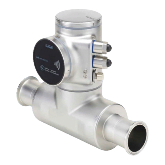
Type 8098 FLOWave L Description DESCRIPTION Device variants The Type 8098 FLOWave L flowmeter is made up of a Type SE98 transmitter and a Type S097 flow sensor. The following pictures describe the main device variants of the Type 8098 FLOWave L flowmeter: • Fig. 1 describes a device with two M20x1.5 cable glands in stainless steel (or in nickel plated brass) and one 5-pin M12 male connector. - Page 15 Type 8098 FLOWave L Description Blind cover or display module (Type ME31) Device status indicator, seal c housing, including the elec- tronic modules Type SE98 transmitter Seal 4-pin M12 female connectors with screwed plugs 5-pin M12 male connector, with screwed plug...
-
Page 16: Wi-Fi Module
Type 8098 FLOWave L Description Wi-Fi module The device can be equipped with a Wi-Fi module in place of or in addition to the display module. The Wi-Fi module has the Type number ME31. The Wi-Fi module has the same functional scope as the display module. -
Page 17: Type Labels
Type 8098 FLOWave L Description Type labels 5.4.1 Adhesive labels 8098 FLOWave L Supply: 12-35 5W Max. IP65 / IP67 / NEMA4X Ambient Temp : -10 to 70°C CAN_H 88888888 SN 9999 CAN_L CAN shield W49MN Made in France 28-06 1. - Page 18 Type 8098 FLOWave L Description 8098 FLOWave L IP65 / IP67 / NEMA 4X Ambient temp.: -10 to 55°C 88888888 SN 9999 CAN_H CAN_L CAN shield W49MN Made in France 28-06 1. IP-Code, NEMA protection type 7. Conformity marking 2. Type of the device 8.
-
Page 19: Laser Marking
Type 8098 FLOWave L Description 5.4.2 Laser marking Supply: 12...35V 5W Max. IP65 | IP67 | NEMA4X Ambient Temp: -10°...+70°C Type: 8098 FLOWave L ID:00xxxxxx | S/N:001234 Slot5: Slot4: W49MN Slot3: Slot2: Slot1: 28-06 Measuring CRN 0C21751.5 Equipment N°E237737 1. Type of the device 8. -
Page 20: Device Status Indicator
Type 8098 FLOWave L Description Device status indicator The device status indicator changes its colour based on the NAMUR NE 107 recommendation. The color of the device status indicator gives the following pieces of information: • Whether device diagnostics are active on not. - Page 21 Type 8098 FLOWave L Technical data TECHNICAL DATA ..........................22 6.1 Operating conditions .........................22 6.2 Conformity to standards and directives ...................23 6.2.1 Conformity to the Pressure Equipment Directive .............23 6.2.2 UL certification......................23 6.2.3 EHEDG certification ....................24 6.2.4 ATEX / IECEx certification ..................24 6.3 Liquid data ..........................25 6.4 Measurement data ........................27 6.4.1 Volume flow rate ......................27 6.4.2 Temperature .......................27 6.4.3 Differentiation factor ....................28 6.4.4...
-
Page 22: Technical Data
1) not evaluated by UL; only IP64 is evaluated by the ATEX / IECEx notified/certification body → For the special operating conditions of devices with ATEX / IECEx certification, refer to the ATEX / IECEx supplement for the device. The supplement is available at country.burkert.com. English... -
Page 23: Conformity To Standards And Directives
Type 8098 FLOWave L Technical data Conformity to standards and directives The applied standards, which verify conformity with the EU Directives, can be found on the EU Type Exami- nation Certificate and/or the EU Declaration of Conformity (if applicable). 6.2.1 Conformity to the Pressure Equipment Directive ▶... -
Page 24: Ehedg Certification
Type 8098 FLOWave L Technical data 6.2.3 EHEDG certification • EL class I • The following device variants are EHEDG certified: Process connections Diameters • Clamp 1) connections according to ASME BPE • 3/8", 1/2", 3/4", 1", 1 1/2", 2", 2 1/2", 3" (DIN 32676 series C) •... -
Page 25: Liquid Data
Type 8098 FLOWave L Technical data Liquid data °C Ambient temperature Temperatures authorized for a limited duration °C Liquid temperature Fig. 9: Dependency between the liquid temperature and the ambient temperature, device variant with two M20x1.5 cable glands and one 5-pin M12 male connector °C Ambient temperature Temperatures authorized for a limited duration °C Liquid temperature Fig. 10: Dependency between the liquid temperature and the ambient temperature, device variant with two 4-pin M12 female connectors and one 5-pin M12 male connector (Ethernet device variant) Liquid temperature –20 °C...+110 °C. Up to 140 °C for maximum 60 minutes for a sterilisation process. - Page 26 Type 8098 FLOWave L Technical data Table 2: Liquid pressure, depending on the pipe diameter, the type of process connections and the process connection standard Size of the process Type of process Standards the process connections connection connection conform to • DIN 11864-3 series B clamp • DIN 32676 series A PN25 DN08, DN15, DN25 • DIN 32676 series B flange DIN 11864-2 series B PN25 clamp DIN 11864-3 series A PN25 DN15, DN25 flange DIN 11864-2 series A...
-
Page 27: Measurement Data
Type 8098 FLOWave L Technical data Size of the process Type of process Standards the process connections connection connection conform to • DIN 32676 series A clamp PN10 • DIN 32676 series B DN65, DN80 external threaded • DIN 11851 PN10 ASME 2 1/2", 3" clamp • DIN 32676 series C PN10 Measurement data 6.4.1 Volume flow rate... -
Page 28: Differentiation Factor
Type 8098 FLOWave L Technical data 6.4.3 Differentiation factor Table 5: DF measurement (optional feature) • Measurement range • 0.8...1.3 • Resolution • 0.00001 • Repeatability • ±0.5 % of the measured value • Refresh time • Adjustable, see chapter 15.16 Setting the refresh time. 6.4.4... -
Page 29: Electrical Data
Type 8098 FLOWave L Technical data Electrical data Voltage not allowed Ambient temperature °C Temperature authorized for a limited duration Supply voltage V DC Liquid temperature °C Fig. 11: Minimum supply voltage depending on the ambient temperature and the liquid temperature, device variant with two M20x1.5 cable glands and one 5-pin M12 male connector Voltage not allowed Ambient temperature °C Temperature authorized for a limited duration Supply voltage V DC... - Page 30 Type 8098 FLOWave L Technical data Operating voltage • 12...35 V DC; the minimum voltage to be supplied depends on the liquid temperature and on the ambient operating tem- perature: depending on the device variant, see Fig. 11 or Fig. 12 • Current consumption: max. 2 A •...
-
Page 31: Mechanical Data
Type 8098 FLOWave L Technical data Mechanical data Dimensions and weight of the device: refer to the technical data sheet regarding Type 8098 FLOWave L available at country.burkert.com Table 9: Materials in contact with ambient air Component Material Transmitter housing1) Stainless steel 304 / 1.4301, outer surface finish Ra < 1.6 µm Stainless steel 304 / 1.4301, outer surface finish Ra < 1.6 µm... -
Page 32: Specifications Of The Ethernet Industrial Communication
Type 8098 FLOWave L Technical data Specifications of the Ethernet Industrial communication Table 12: Specifications of the industrial communication module Network speed 10/100 mbps Auto negotiation Auto MDI/MDI-X Switch function Network diagnostics Yes, via error telegram Individual identification number, stored in the module and on the... -
Page 33: Profinet Protocol
Type 8098 FLOWave L Technical data 6.7.2 PROFINET protocol Product type Compact field IO device PROFINET IO specification V2.3 Network topology • Tree • Star • Ring (closed daisy chain) • Line (open daisy chain) Network management • LLDP (Link Layer Discovery Protocol) •... -
Page 34: Ethernet/Ip Protocol
Type 8098 FLOWave L Technical data 6.7.3 EtherNet/IP protocol Protocol Internet protocol, version 4 (IPv4) Network topology • Tree • Star • DLR (Device Level Ring) for closed daisy chain • Linear for open daisy chain IP configuration • Static IP address •... -
Page 35: Ethercat Protocol
Type 8098 FLOWave L Technical data 6.7.4 EtherCAT protocol • X1: EtherCAT IN Industrial Ethernet interface X1, X2 • X2: EtherCAT OUT 512 bytes in total Maximum number of cyclic input and output data 1024 bytes Maximum number of cyclic input data... - Page 36 Type 8098 FLOWave L Technical data English...
- Page 37 Type 8098 FLOWave L Installation in the pipe INSTALLATION IN THE PIPE ........................38 7.1 Safety instructions ........................38 7.2 Additional documentation ......................39 7.3 Preparing the device before installation into the pipe .............39 7.3.1 Changing the position of the transmitter on the sensor ..........39 7.3.2 Switching positions of the blind cover and the display module or the Wi-Fi module ......................43 7.4 Recommendations for the installation into the pipe ..............46 7.5 Installing the device into the pipe .....................49 7.5.1 Before installing the device into the pipe ..............49 7.5.2 Installing a device with clamp connections .............49 7.5.3...
-
Page 38: Installation In The Pipe
Type 8098 FLOWave L Installation in the pipe INSTALLATION IN THE PIPE Safety instructions DANGER Risk of injury due to electrical voltage. ▶ Before carrying out work on the system, disconnect the electrical power for all the conductors and isolate it. ▶ In accordance with standard UL/EN 61010-1, all equipment connected to the Type 8098 FLOWave L flowme- ter shall be double insulated with respect to the mains and all circuits connected to the Type 8098 FLOWave L... -
Page 39: Additional Documentation
Additional documentation → If the device is an ATEX / IECEx device variant, then refer to the ATEX / IECEx supplement for Type 8098 FLOWave L available on the internet at country.burkert.com. Preparing the device before installation into the pipe The device is delivered as described in chapter 5.1. - Page 40 Type 8098 FLOWave L Installation in the pipe Fig. 13: Possible positions of the transmitter SE98 → To change the position of the transmitter, do the following: For safety reasons and to comply with standard UL 61010-1, the blind cover and the display module or the Wi-Fi module are locked.
- Page 41 Type 8098 FLOWave L Installation in the pipe Carefully lift the display module or the Wi-Fi module because a cable connects the display module or the Wi-Fi module to the transmitter. 4. Push the tab of the cable connector to dis- connect the display module or the Wi-Fi module from the transmitter.
- Page 42 Type 8098 FLOWave L Installation in the pipe Lift the transmitter carefully because a cable connects the transmitter to the flow sensor. 9. If the seal is damaged, replace it. Apply a layer of lithium soap grease to the new seal before you put it in place.
-
Page 43: Switching Positions Of The Blind Cover And The Display Module Or The Wi-Fi Module
Type 8098 FLOWave L Installation in the pipe 14. Screw the transmitter clockwise on the flow sensor until the blind cover is perfectly parallel or perpendicular to the axis of the pipe. 15. Fasten the screw with a size 3 hexagonal key to a tightening torque of 1.3 ±0.5 Nm... - Page 44 Type 8098 FLOWave L Installation in the pipe For safety reasons and to comply with standard UL 61010-1, the blind cover and the display module or the Wi-Fi module are locked. → Prepare the unlocking magnetic key, which is delivered with the device.
- Page 45 Type 8098 FLOWave L Installation in the pipe 6. Put the magnetic key on the mark related to the blind cover. You should hear a click indi- cating that the blind cover is unlocked. Do not use a tool to turn the blind cover.
-
Page 46: Recommendations For The Installation Into The Pipe
Type 8098 FLOWave L Installation in the pipe Recommendations for the installation into the pipe The device can be installed into either horizontal, oblique or vertical pipes. But an installation on a vertical pipe is better to prevent air bubbles or gas bubbles to remain in the sensor measurement-tube. - Page 47 Type 8098 FLOWave L Installation in the pipe → To make sure that neither air bubbles nor gas bubbles trouble the measuring, install the device as rec- ommended in Fig. 15. flow direction α flow direction Recommended Not recommended Not recommended α is the minimum angle to the horizontal for proper self-draining (see Table 13) Fig. 15:...
- Page 48 Type 8098 FLOWave L Installation in the pipe No pipe insulation Pipe insulation Fig. 16: Thermal insulation of the pipe → To make sure the internal temperature of the transmitter with cable glands does not exceed the authorized maximum value, install the device as recommended in Fig. 17.
-
Page 49: Installing The Device Into The Pipe
Type 8098 FLOWave L Installation in the pipe Installing the device into the pipe CAUTION Risk of injury due to a heavy device. A heavy device can fall down during transport or during installation and cause injuries. ▶ Transport, install and dismantle a heavy device with the help of another person. -
Page 50: Installing A Device With External-Threaded Connections According To Din 11851 Series A For Pipes According To Din 11850
• 2 conical ferrules • 2 gaskets that respect the standard DIN 11851. If the installation must be EHEDG-compliant, then supply EHEDG-compliant gaskets. For an EHEDG-compliant use, Burkert recommends gaskets of one of the fol- lowing type: − ASEPTO-STAR k-flex upgrade gaskets from Kieselmann GmbH, Germany, −... - Page 51 Type 8098 FLOWave L Electrical installation ELECTRICAL INSTALLATION .......................52 8.1 Safety instructions ........................52 8.2 Additional documentation ......................54 8.3 Connecting the device to a power supply ................54 8.4 Connecting the device to a büS / CANopen network ..............55 8.5 Activating the device internal termination resistor ..............57 8.6 Specifications of the cables for the M20x1.5 cable glands (device variant with cable glands) ............................57 8.7 Specifications of the conductors for the 12 push-in terminal strip .........58 8.8 Terminal assignment of the 12 push-in terminal strip ..............58 8.9 Opening the front of the transmitter ..................59 8.10 Wiring the device through the M20x1.5 cable glands in stainless steel (device variant with cable glands) ........................61 8.11 Wiring the device through the M20x1.5 cable glands in nickel plated brass (device...
-
Page 52: Electrical Installation
Type 8098 FLOWave L Electrical installation ELECTRICAL INSTALLATION Safety instructions DANGER Risk of injury due to electrical voltage. ▶ Before carrying out work on the system, disconnect the electrical power for all the conductors and isolate it. ▶ In accordance with standard UL/EN 61010-1, all equipment connected to the Type 8098 FLOWave L flowmeter shall be double insulated with respect to the mains and all circuits connected to the Type 8098 FLOWave L flowmeter must be limited energy circuits. - Page 53 Type 8098 FLOWave L Electrical installation WARNING Risk of injury due to non-conforming installation. ▶ The electrical and liquid installations must only be carried out by qualified and authorized personnel with the appropriate tools. ▶ Fit a circuit breaker or a switch to the electrical installation of the building in which the device is installed.
-
Page 54: Additional Documentation
"CANopen Network configuration" at country.burkert.com. • If the device is an ATEX / IECEx device variant, then refer to the ATEX / IECEx supplement for Type 8098 FLOWave L available on the internet at country.burkert.com. Connecting the device to a power supply The device is wired in the factory to be easily energized through the 5-pin M12 male connector. -
Page 55: Connecting The Device To A Büs / Canopen Network
Type 8098 FLOWave L Electrical installation The minimum voltage to be supplied depends on the device variant, on the liquid temperature and on the ambient operating temperature: see Fig. 20 and Fig. 21. Voltage not allowed Ambient temperature °C Temperature authorized for a limited duration Supply voltage V DC... - Page 56 Type 8098 FLOWave L Electrical installation → To connect the device, remove the screwed plug of the 5-pin M12 male connector and store the screwed plug in a safe and clean place. Risk of damage to the device if an M12 connector is unused.
-
Page 57: Activating The Device Internal Termination Resistor
Type 8098 FLOWave L Electrical installation Activating the device internal termination resistor The device has an internal termination resistor that can be activated if the device is installed at one end of a büS network or of a CANopen network. -
Page 58: Specifications Of The Conductors For The 12 Push-In Terminal Strip
Type 8098 FLOWave L Electrical installation Specifications of the conductors for the 12 push-in terminal strip Table 16: Specifications of the conductors for the terminal strip Specification of the conductors Recommended value range Cross section of a solid conductor H05(07) V-U 0.25...1.5 mm Cross section of a stranded conductor H05(07) V-K, 0.25...1.5 mm with a wire ferrule but without collar Cross section of a stranded conductor H05(07) V-K, 0.25...0.75 mm... -
Page 59: Opening The Front Of The Transmitter
Type 8098 FLOWave L Electrical installation On a device with two 4-pin M12 female connectors (Ethernet device variant), do not use terminals 6 to 12. • Terminal 6: GND (for the connection of the power supply through the M20x1.5 cable glands) •... - Page 60 Type 8098 FLOWave L Electrical installation Procedure to open the front of the transmitter if the display module or the Wi-Fi module is on the front of the device 1. Remove the blind cover from the top of the transmitter. 2. Put the magnetic key on the mark related to the display module or the Wi-Fi module. You should hear a click indicating that the display module or the Wi-Fi module is unlocked.
-
Page 61: Wiring The Device Through The M20X1.5 Cable Glands In Stainless Steel (Device Variant With Cable Glands)
Type 8098 FLOWave L Electrical installation 8.10 Wiring the device through the M20x1.5 cable glands in stainless steel (device variant with cable glands) Put only one cable in each cable gland. → Prepare cables that obey the specifications given in chapter 8.6 and chapter 8.7. - Page 62 Type 8098 FLOWave L Electrical installation 12. Put the functional earth plate in its original place. Functional earth 13. Use a size 10 hexagonal key to tighten the 2 screws of the functional earth plate to a torque of 0.2 Nm (0.15 ft·lbf).
-
Page 63: Wiring The Device Through The M20X1.5 Cable Glands In Nickel Plated Brass (Device Variant With Cable Glands)
Type 8098 FLOWave L Electrical installation 8.11 Wiring the device through the M20x1.5 cable glands in nickel plated brass (device variant with cable glands) Put only one cable in each cable gland. → Prepare cables that obey the specifications given in chapter 8.6 and chapter 8.7. - Page 64 Type 8098 FLOWave L Electrical installation 10. Attach each cable to the functional earth plate. The shield must be in contact with the functional earth plate. 11. Put the functional earth plate in its original place. Functional earth 12. With an hexagonal key size 10, tighten the 2 screws of the functional earth plate to a torque of 0.2 Nm (0.15 ft·lbf).
-
Page 65: Connecting The Functional Earth (Device Variant With Two M20X1.5 Cable Glands)
Type 8098 FLOWave L Electrical installation 8.12 Connecting the functional earth (device variant with two M20x1.5 cable glands) → For a proper function of device always connect the yellow/green functional earth conductor: − either to the functional earth plate in the transmitter housing (see Fig. 31 in chapter 8.13), −... - Page 66 Type 8098 FLOWave L Electrical installation To connect to the positive 12...35 V DC power supply for the device through a cable gland To connect to the negative power supply for the device through a cable gland Green LED flashes slowly if the operation of the...
-
Page 67: Wiring Output 1 (Analogue) And Output 3 Configured As An Analogue Output
Type 8098 FLOWave L Electrical installation 8.14 Wiring output 1 (analogue) and output 3 configured as an analogue output (device variant with cable glands) NOTICE Risk of short-circuit if the configuration of output 3 is wrong. ▶ Before wiring output 3 as an analogue output, make sure output 3 is configured as an analogue output in the Parameter menu of the outputs. -
Page 68: Wiring Output 2 (Digital) And Output 3 Configured As A Digital Output
Type 8098 FLOWave L Electrical installation 8.15 Wiring output 2 (digital) and output 3 configured as a digital output (device variant with cable glands) NOTICE Risk of short-circuit if the configuration of output 3 is wrong. ▶ Before wiring output 3 as a digital output, make sure output 3 is configured as a digital output in the Parameter menu of the outputs. -
Page 69: Knowing The Status Of The Ethernet Network (Device Variant With Two 4-Pin M12 Female Connectors - Ethernet Device Variant)
Type 8098 FLOWave L Electrical installation 8.16 Knowing the status of the Ethernet network (device variant with two 4-pin M12 female connectors – Ethernet device variant) The status of the Ethernet network is indicated by LEDs. The LEDs are located on the industrial communi- cation module in the transmitter housing. -
Page 70: Specifications Of The Cables And Conductors For The 4-Pin M12 Female Connectors
Type 8098 FLOWave L Electrical installation 8.17 Specifications of the cables and conductors for the 4-pin M12 female connectors Table 19: Specifications of the cables and conductors for the 4-pin M12 female connectors Specification of the cables and conductors Recommended value Electromagnetic protection (EMC) Shielded conductor with minimum STP Minimum category CAT-5 Maximum length 100 m Maximum operating temperature 80 °C or higher... -
Page 71: Connecting The Functional Earth (Device Variant With Two 4-Pin M12 Female Connectors - Ethernet Device Variant)
Type 8098 FLOWave L Electrical installation Cable and conductors connected inside the device from X1 to the upper 4-pin M12 female connector Cable and conductors connected inside the device from X2 to the middle 4-pin M12 female connector Cable and conductors connected... - Page 72 Type 8098 FLOWave L English...
- Page 73 Type 8098 FLOWave L Commissioning COMMISSIONING ..........................74 9.1 Safety instructions ........................74 9.2 Prerequisites ..........................74 9.3 First commissioning for measuring the flow rate or for filling containers .......74 9.4 First commissioning for detecting a change of liquid in the pipe ..........76 9.5 First commissioning for detecting bubbles in the pipe ............77 English...
- Page 74 Type 8098 FLOWave L Commissioning COMMISSIONING Safety instructions WARNING Risk of injury due to non-conforming commissioning. Non-conforming commissioning could lead to injuries and damage the device and its surroundings. ▶ Before commissioning, make sure that the staff in charge have read and fully understood the contents of the operating instructions.
- Page 75 Type 8098 FLOWave L Commissioning 7. Set the parameter for the liquid: Viscosity compensation • If the liquid is water, then make sure that the parameter Viscosity compensation is set to water. Refer to chapter 15.15. • If the liquid has a kinematic viscosity that is between 0.5 and 2 mm...
- Page 76 Type 8098 FLOWave L Commissioning 17. With the Bürkert Communicator software, print a pdf report of the new settings of the device. 18. Select the process values that you want to save and export the selected data under the format (*.edipdb).
- Page 77 Type 8098 FLOWave L Commissioning First commissioning for detecting bubbles in the pipe 1. Energise the device. 2. Connect the device to the Bürkert Communicator software. Print a pdf report of all the current settings of the device. Select the process values that you want to monitor graphically. Refer to the Type 8920 Bürkert Communicator software from country.burkert.com.
- Page 78 Type 8098 FLOWave L Commissioning English...
- Page 79 Type 8098 FLOWave L Doing the settings HOW TO DO THE SETTINGS .......................80 10.1 Safety instructions ........................80 10.2 Available software to do the settings ..................80 10.3 Connect the device to the Bürkert Communicator software ...........80 10.4 Display module: description of the user interface ..............82 10.4.1 Description of the display ..................83 10.4.2 How to use the touch sensitive keys ................84 10.4.3 Minimum and maximum values when entering a numerical value ......84 10.5 Available login user levels ......................84 10.6 Default settings ..........................85 10.7 Menu structure ...........................86...
-
Page 80: How To Do The Settings
1. Buy the USB-büS interface set with article number 772426 from Bürkert. 2. Download the latest version of the Type 8920 Bürkert Communicator software from country.burkert.com. 3. Install the Bürkert Communicator software on a PC. Obey the installation recommendations given in the USB-büS interface set. - Page 81 Type 8098 FLOWave L How to do the settings 6. Insert the mini-USB of the cable into the delivered büS stick. Do not insert the mini-USB of the cable into any equipment other than the büS stick. 7. Insert the appropriate power adapter into the AC/DC adapter.
-
Page 82: Display Module: Description Of The User Interface
Display module: description of the user interface To get detailed information on the display software, refer to the Operating Instructions of the Type ME31 display software, available on the internet at country.burkert.com. The user interface is made up of a display and touch sensitive keys. -
Page 83: Description Of The Display
Type 8098 FLOWave L How to do the settings 10.4.1 Description of the display Symbol of the active user level. See chapter 10.5 Available login user Symbol of the device levels. status Information bar Display Parameter To the DIAG- Brightness 56 %... -
Page 84: How To Use The Touch Sensitive Keys
Type 8098 FLOWave L How to do the settings 10.4.2 How to use the touch sensitive keys highlighted terms are related to menus or menu items. Table 20: How to use the keys Description Short press: to go back to the parent menu or to the parent view. This key is called BACK in the display messages. -
Page 85: Default Settings
Type 8098 FLOWave L How to do the settings Table 21 shows the symbol displayed in the information bar, depending on the user level that is active on the device, and what can be done with each type of user level. -
Page 86: Menu Structure
Type 8098 FLOWave L How to do the settings 10.7 Menu structure View 1 of 4 CONFIGURATION Volume flow 30.1 SAW sensor To navigate through the list l/min of available menu items Configuration view First view, displayed after energizing the device, that... -
Page 87: Opening Or Closing The Context Menu In Any View (Display Module Only)
Type 8098 FLOWave L How to do the settings 10.7.1 Opening or closing the context menu in any view (display module only) The user can open a context menu in any view. The content depends on the active view. To open the context menu: →... -
Page 88: Adding Your Own Context Menu Items (Shortcuts, Display Module Only)
Type 8098 FLOWave L How to do the settings View Menu items of the context menu Messages overview To display the list of messages generated by the device. Save To save the changes. To display the access path to the displayed menu item. Not... -
Page 89: Reading Out The Messages Generated By The Device
→ To read out the messages in the Bürkert Communicator software, refer to the Operating Instructions Type 8920, available on the internet at country.burkert.com. Do the following to display the generated messages on the display module: →... -
Page 90: Changing The Login User Level If The Adjustment Is Protected Through Passwords
• you are automatically logged out after the activation delay of the screen saver has elapsed. → To log out from the active user level in the Bürkert Communicator software, refer to the Operating Instructions Type 8920, available on the internet at country.burkert.com. Do the following to log out from the Advanced user, the or the... -
Page 91: Reading Out The Access Path To A Menu Item (Display Module Only)
Type 8098 FLOWave L How to do the settings 10.7.7 Reading out the access path to a menu item (display module only) If you are lost in the menu structure, you can display the access path. → Long press, to open the context menu. -
Page 92: Navigating In A Wizard And Adjusting Numbers
Type 8098 FLOWave L How to do the settings 10.8.2 Navigating in a wizard and adjusting numbers General settings Parameter Quick start Diagnostics Date and time Language English Confirm Parameter Current date/time 1/9 Current date:08/24/15 Current time:08:57:16 Daylight savings... -
Page 93: Setting Negative Or Positive Numbers
Type 8098 FLOWave L How to do the settings 10.8.3 Setting negative or positive numbers Settings Error low max: 150.00 -020.000 min: -20.00 To set a positive number: → to increase the number until the positive value is reached. Settings Error low max: 150.00... -
Page 94: Entering A Name
Type 8098 FLOWave L How to do the settings 10.8.4 Entering a name SAW sensor Parameter Stand. meas. values [+] Add. meas. values [+] Diag. events Refresh time Long Confirm SAW sensor Stand. meas. values Volume flow Temperature Liquid velocity Totalizer 1 Confirm SAW sensor... -
Page 95: Activating Or Deactivating A Feature
Type 8098 FLOWave L How to do the settings 10.8.5 Activating or deactivating a feature General settings Parameter Date and Time Language English Passwords Physical units Confirm Parameter Passwords Password protection Confirm Passwords Password protection Deactivate / Activate Save Fig. 48:... - Page 96 Type 8098 FLOWave L English...
- Page 97 Type 8098 FLOWave L Menu Display DISPLAY MODULE SETTINGS......................98 11.1 Safety instructions ........................98 11.2 Doing the Quick start adjustments when energizing the device for the first time (display module only) .........................98 11.3 Menu Parameter .........................99 11.3.1 Adjusting the brightness of the display backlight ............99 11.3.2 Adjusting the contrast of the display ................99 11.3.3 Adjusting the activation delay of the screen saver ..........100 11.3.4 Adjusting the brightness of the backlight by active screen saver ......100 11.3.5 Unlocking the screen saver ..................101 11.3.6 Changing the unlock sequence of the screen saver ..........101 11.4 Menu Diagnostics ........................102 11.4.1...
-
Page 98: Display Module Settings
Type 8098 FLOWave L Display module settings DISPLAY MODULE SETTINGS The section describes the menus related to the display module which is fitted on the device. 11.1 Safety instructions WARNING Risk of injury due to non-conforming adjustment. Non-conforming adjustment could lead to injury and damage the device and its surroundings. -
Page 99: Menu Parameter
Type 8098 FLOWave L Display module settings 11.3 Menu Parameter 11.3.1 Adjusting the brightness of the display backlight The brightness of the display is automatically reduced if the internal device temperature is higher than +60 °C. If the internal device temperature is higher than +60 °C, the brightness of the display is automati- cally reduced to 50 % and the backlight is even switched off 5 minutes after the last operation. If the temperature is higher than 80 °C the backlight is automatically switched off (0 %). -
Page 100: Adjusting The Activation Delay Of The Screen Saver
Type 8098 FLOWave L Display module settings 11.3.3 Adjusting the activation delay of the screen saver The screen saver allows you to: • Save energy. • Automatically go back to View 1. • And, if the adjustment is protected through passwords, to be automatically logged out from an... -
Page 101: Unlocking The Screen Saver
Type 8098 FLOWave L Display module settings 11.3.5 Unlocking the screen saver To unlock the display when the screen saver is active, do the following to have access to any view again: → Press any key twice. The first key of the unlock sequence is displayed. -
Page 102: Menu Diagnostics
Type 8098 FLOWave L Display module settings 11.4 Menu Diagnostics 11.4.1 Reading out the temperature of the display module To read out the temperature of the display module, do the following: → Go to the CONFIGURATION view. → Display →... -
Page 103: Reading Out The Version Number Of The Hardware Of The Display Module
Type 8098 FLOWave L Display module settings 11.5.2 Reading out the version number of the hardware of the display module To read out the version number of the hardware of the display module, do the following: → Go to the CONFIGURATION view. -
Page 104: Reading Out The Article Number Of The Display Module Software
Type 8098 FLOWave L Display module settings 11.5.4 Reading out the article number of the display module software To read out the article number of the display module software, do the following: → Go to the CONFIGURATION view. → Display →... - Page 105 Type 8098 FLOWave L Menu General settings GENERAL SETTINGS – PARAMETER ....................108 12.1 Safety instructions ........................108 12.2 User levels of the editable menu items ..................108 12.3 Default settings ........................108 12.4 Changing the operating mode of the device status indicator or switching off the device status indicator ......................109 12.4.1 Changing the operating mode of the device status indicator .......109 12.4.2 Switching off the device status indicator ...............109 12.5 Setting the basic parameters for identifying the device on büS ..........110 12.5.1 Entering a name for the device ................110 12.5.2 Entering the location of the device .................110 12.5.3 Entering a description for the device ..............111 12.6 Setting the advanced parameters for identifying the device connected to büS or to a CANopen bus ...........................111...
- Page 106 Type 8098 FLOWave L 12.13 Changing the date and the time .....................123 12.14 Changing the display language ....................123 12.15 Activating the adjustment protection through passwords ............124 12.16 Changing the protection passwords of the Advanced user and Installer user levels ..124 12.17 Deactivating the adjustment protection through passwords ..........125 12.18 Changing the units of the physical quantities ...............125 12.19 Displaying the text -- (NaN) or a numerical value ..............126 GENERAL SETTINGS – DIAGNOSTICS .....................127 13.1 User levels of the menu items ....................127 13.2 Reading out data related to the device ...................127 13.2.1 Reading out the number of operating hours of the device ........127 13.2.2 Reading out the current value of the internal temperature of the device .....128 13.2.3 Reading out the minimum or the maximum value of the internal tempera- ture of the device .....................128 13.2.4 Reading out the current value of the supply voltage ..........128 13.2.5 Reading out the minimum or the maximum value of the supply voltage ....129 13.2.6...
- Page 107 Type 8098 FLOWave L 13.4 Configuration provider information ..................134 13.4.1 Reading out the current status of the configuration provider .......134 13.4.2 Reading out the number of loaded client (module) configurations .......135 13.4.3 Reading out the number of reconfigured clients (modules) ........135 13.4.4 Reading out the number of managed modules ............135 13.4.5 Reading out the number of missing modules ............136 13.4.6 Reading out the number of failed configuration loads ..........136 13.4.7 Reading out the number of failed reconfigurations ..........137 13.4.8 Erasing the configuration data of a single module ..........137 GENERAL SETTINGS – MAINTENANCE ...................138 14.1 User levels of the menu items ....................138 14.2 Reading out some device information ..................138 14.2.1 Reading out the displayed name of the device ............138...
-
Page 108: General Settings - Parameter
Type 8098 FLOWave L General settings – Parameter GENERAL SETTINGS – PARAMETER 12.1 Safety instructions WARNING Risk of injury due to non-conforming adjustment. Non-conforming adjustment could lead to injury and damage the device and its surroundings. ▶ The operators in charge of adjustment must have read and understood the contents of the Operating Instructions. -
Page 109: Changing The Operating Mode Of The Device Status Indicator Or Switching Off The Device Status Indicator
Type 8098 FLOWave L General settings – Parameter 12.4 Changing the operating mode of the device status indicator or switching off the device status indicator By default, the device status indicator operates according to the NAMUR NE 107 standard (NAMUR mode). The following other operating modes of the device status indicator are available: •... -
Page 110: Setting The Basic Parameters For Identifying The Device On Büs
Type 8098 FLOWave L General settings – Parameter 12.5 Setting the basic parameters for identifying the device on büS The Displayed name, the Location and the Description allow you to clearly identify the device on büS. 12.5.1 Entering a name for the device The entered name will be shown on any display (e.g. -
Page 111: Entering A Description For The Device
Type 8098 FLOWave L General settings – Parameter 12.5.3 Entering a description for the device The description allows you to precisely identify this device. To enter a description for the device, do the following:. → Go to the CONFIGURATION view. -
Page 112: Changing The Transmission Speed On The Device
Type 8098 FLOWave L General settings – Parameter → OK → Save the name. The unique name is set. 12.6.2 Changing the transmission speed on the device The transmission speed for the communication on the fieldbus (both büS or CANopen) must be the same for all the participants of the fieldbus. -
Page 113: Deactivating The Device Internal Termination Resistor
Type 8098 FLOWave L General settings – Parameter → Confirm to access the Parameter view. → büS → Advanced → Termination resistor → On → Save. The internal termination resistor is activated. 12.6.4 Deactivating the device internal termination resistor If the device is not installed at the end of büS or of a CANopen fieldbus, deactivate the device internal ter- mination resistor. -
Page 114: Setting The Digital Communication For Büs Or For A Canopen Bus
Type 8098 FLOWave L General settings – Parameter → General settings → Confirm to access the Parameter view. → büS Advanced → büS address → Change the address of the device. Make sure you enter an address that is not already used on the same CANopen fieldbus. -
Page 115: Stop Sending The Measured Process Data (Pdos) To Büs Or To The Canopen Fieldbus
Type 8098 FLOWave L General settings – Parameter 12.6.7 Stop sending the measured process data (PDOs) to büS or to the CANopen fieldbus If the device is connected to büS or to a CANopen fieldbus and the Bus mode is set to büS... - Page 116 Type 8098 FLOWave L General settings – Parameter h: value of the hysteresis. A hys- teresis value that is equal to 0 means that the device reacts as soon as a limit is reached. A: low error limit (Error low) B: low warning limit (Warning low)
-
Page 117: Reading Out The 2 Error Limit Values
Type 8098 FLOWave L General settings – Parameter 12.7.1 Reading out the 2 error limit values To read out the limits the supply voltage of the device should be in, do the following: → Go to the view. CONFIGURATION →... -
Page 118: Reading Out The Low Warning Limit For The Voltage Of The Internal Battery
Type 8098 FLOWave L General settings – Parameter → Hysteresis → Go back to the parent menu. 12.8 Reading out the low warning limit for the voltage of the internal battery The device has a small battery to store energy so that the time system can run for 7 days when the device is not powered. -
Page 119: Activating The Diagnostics Function
Type 8098 FLOWave L General settings – Parameter → Set the hours → Set the minutes The new date and time settings are displayed. → Choose the unit system for all the measurements Confirm. → Save the Quick start settings or go back to the parent menu without saving the new settings. -
Page 120: Disabling All The Diagnostics
Type 8098 FLOWave L General settings – Parameter 12.11 Disabling all the diagnostics By default, all the diagnostics events related to the process, the electronics or the sensor, the messages related to the monitoring of the process values (e.g. the flow rate) and the messages related to problems on the device and on büS are disabled. -
Page 121: Reading Out The Status Of The Configuration Provider
Type 8098 FLOWave L General settings – Parameter • On request, the configuration provider replaces the configuration data on the memory card with the current configuration data of the equipped modules. See chapter 12.12.2. For example, this is useful to remove from the configuration memory, the configuration data of a removed module. -
Page 122: Replacing The Data Of The Configuration Memory
Type 8098 FLOWave L General settings – Parameter 12.12.2 Replacing the data of the configuration memory If you want to replace the configuration data which is stored on the configuration memory by the current configuration data of all the device modules, do the following: →... -
Page 123: Changing The Date And The Time
Type 8098 FLOWave L General settings – Parameter 12.13 Changing the date and the time The date and time are set in the settings when the device is energized for the first time. Quick start To change the date and time, do the following: →... -
Page 124: Activating The Adjustment Protection Through Passwords
Type 8098 FLOWave L General settings – Parameter 12.15 Activating the adjustment protection through passwords By default, the device adjustment is not protected by passwords. The default user level is the Installer level. To activate the adjustment protection through passwords, do the following: →... -
Page 125: Deactivating The Adjustment Protection Through Passwords
Type 8098 FLOWave L General settings – Parameter 12.17 Deactivating the adjustment protection through passwords By default, the device adjustment is not protected by passwords. The default user level is the Installer level. If the adjustment protection through passwords has been activated, do the following to deactivate it: →... -
Page 126: Displaying The Text -- (Nan) Or A Numerical Value
Type 8098 FLOWave L General settings – Parameter → General settings → Confirm to access the Parameter view. → Physical units → Choose the physical quantity → Choose the units Save The units are changed. 12.19 Displaying the text (NaN) or a numerical value... -
Page 127: General Settings - Diagnostics
Type 8098 FLOWave L General settings – Diagnostics GENERAL SETTINGS – DIAGNOSTICS 13.1 User levels of the menu items Menu item of the General settings – Diagnostics menu Minimum user level Device status Basic user büS status – Receive errors Advanced user büS status – Receive errors max. -
Page 128: Reading Out The Current Value Of The Internal Temperature Of The Device
Type 8098 FLOWave L General settings – Diagnostics 13.2.2 Reading out the current value of the internal temperature of the device To read out the current value of the internal temperature of the device, do the following: → Go to the CONFIGURATION view. -
Page 129: Reading Out The Minimum Or The Maximum Value Of The Supply Voltage
Type 8098 FLOWave L General settings – Diagnostics → Supply voltage The value of the supply voltage is displayed. → Go back to the parent menu. 13.2.5 Reading out the minimum or the maximum value of the supply voltage To read out the minimum or the maximum value of the supply voltage since the last power-up of the device, do the following: →... -
Page 130: Reading Out The Minimum Or The Maximum Value Of The Current Consumption Of The Device
Type 8098 FLOWave L General settings – Diagnostics 13.2.7 Reading out the minimum or the maximum value of the current consumption of the device To read out the minimum or the maximum value of the current consumption of the device since the first power-up of the device, do the following: →... -
Page 131: Checking Whether The Date And Time Are Correct
Type 8098 FLOWave L General settings – Diagnostics → Device status → Transferable memory status → Go back to the parent menu. 13.2.10 Checking whether the date and time are correct To check whether the date and time are still correct on the device, do the following: →... -
Page 132: Reading Out Data Related To Büs
Type 8098 FLOWave L General settings – Diagnostics 13.3 Reading out data related to büS 13.3.1 Reading out the number of current receive errors To read out the number of current receive errors, do the following: → Go to the CONFIGURATION view. -
Page 133: Reading Out The Maximum Number Of Transmit Errors Since The Last Power-Up Of The Device
Type 8098 FLOWave L General settings – Diagnostics → Transmit errors → Go back to the parent menu. 13.3.4 Reading out the maximum number of transmit errors since the last power-up of the device To read out the maximum number of transmit errors, do the following: →... -
Page 134: Configuration Provider Information
Type 8098 FLOWave L General settings – Diagnostics → Go to the DIAGNOSTICS view. → büS status → CANopen status • If the CANopen status is Operational, the PDOs are sent to büS. • If the CANopen status is Pre-Op (pre-operational), the PDOs are not sent on büS or on the CANopen fieldbus and a message is generated in the message list. -
Page 135: Reading Out The Number Of Loaded Client (Module) Configurations
Type 8098 FLOWave L General settings – Diagnostics 13.4.2 Reading out the number of loaded client (module) configurations The value is valid since the last device start-up. Do the following: → Go to the CONFIGURATION view. → General settings → Confirm to access the Parameter view. -
Page 136: Reading Out The Number Of Missing Modules
Type 8098 FLOWave L General settings – Diagnostics → Configuration provider → Number of managed devices → Go back to the parent menu. 13.4.5 Reading out the number of missing modules The value is valid since the last device start-up. Do the following: →... -
Page 137: Reading Out The Number Of Failed Reconfigurations
Type 8098 FLOWave L General settings – Diagnostics 13.4.7 Reading out the number of failed reconfigurations The value is valid since the last device start-up. Do the following: → Go to the CONFIGURATION view. → General settings → Confirm to access the view. -
Page 138: General Settings - Maintenance
Type 8098 FLOWave L General settings – Maintenance GENERAL SETTINGS – MAINTENANCE 14.1 User levels of the menu items Menu item of the General settings – Maintenance menu Minimum user level Device information Basic user Reset device Installer 14.2 Reading out some device information 14.2.1... -
Page 139: Reading Out The Serial Number Of The Device
Type 8098 FLOWave L General settings – Maintenance 14.2.3 Reading out the serial number of the device To read out the serial number of the device, do the following: → Go to the CONFIGURATION view. → General settings → Confirm to access the Parameter view. -
Page 140: Reading Out The Version Number Of The Büs Software
Type 8098 FLOWave L General settings – Maintenance 14.2.6 Reading out the version number of the büS software To read out the version number of the büS software, do the following: → Go to the CONFIGURATION view. → General settings →... -
Page 141: Reading Out The Manufacturing Date Of The Device
→ Confirm to access the view. Parameter → Go to the MAINTENANCE view. → Device information → eds version → Go back to the parent menu. The content of the eds file is described in the related supplement available at country.burkert.com. English... -
Page 142: Resetting The Device
Type 8098 FLOWave L General settings – Maintenance 14.3 Resetting the device WARNING Risk of injury due to non-conforming adjustment. Non-conforming adjustment could lead to injuries and damage the device and its surroundings. ▶ The operators in charge of adjustment must have read and understood the contents of the Operating Instructions. -
Page 143: Updating The Menu Configuration Of The Device
Type 8098 FLOWave L General settings – Maintenance 14.3.3 Updating the menu configuration of the device If the hardware configuration of the device has changed, update the configuration of the menu structure: • To have access to the menu entries related to the new components. - Page 144 Type 8098 FLOWave L English...
- Page 145 Type 8098 FLOWave L Menu – SAW sensor PARAMETER SAW SENSOR – PARAMETER ......................150 15.1 Safety instructions ........................150 15.2 User levels of the editable menu items ...................150 15.3 Default settings ........................150 15.4 Setting the parameters of the volume flow rate ..............151 15.4.1 Giving a user defined name to the measured volume flow rate ......151 15.4.2 Activating the damping of the volume flow rate values and choosing a predefined damping level ..................151 15.4.3 Activating a user-defined damping of the volume flow rate values ......153 15.4.4 Deactivating the damping of the volume flow rate values ........154 15.4.5 Activating the monitoring of the volume flow rate ..........154 15.4.6 Deactivating the monitoring of the volume flow rate ..........156 15.4.7...
- Page 146 Type 8098 FLOWave L 15.6 Setting the parameters of the liquid temperature..............173 15.6.1 Giving a user defined name to the measured liquid temperature ......173 15.6.2 Activating the damping of the liquid temperature values and choosing a predefined damping level ..................173 15.6.3 Activating a user-defined damping of the liquid temperature values ....175 15.6.4 Deactivating the damping of the liquid temperature values ........176 15.6.5 Activating the monitoring of the liquid temperature ..........176 15.6.6 Deactivating the monitoring of the liquid temperature ..........177 15.6.7 Changing the error limits, the warning limits and the hysteresis of the liquid temperature ....................178 15.6.8 Resetting the default values of the error limits, the warning limits and the hysteresis of the liquid temperature ..................178 15.6.9 Resetting the default values of all the liquid temperature parameters ....179 15.7 Setting the parameters of the liquid concentration ..............180 15.7.1 Giving a user defined name to the measured liquid concentration ......180...
- Page 147 Type 8098 FLOWave L 15.9 Setting the parameters of the liquid density ................194 15.9.1 Giving a user defined name to the measured liquid density .........194 15.9.2 Activating the damping of the liquid density values and choosing a pre- defined damping level .....................194 15.9.3 Activating a user-defined damping of the liquid density values ......196 15.9.4 Deactivating the damping of the liquid density values ..........197 15.9.5 Activating the monitoring of the liquid density ............197 15.9.6 Deactivating the monitoring of the liquid density ..........198 15.9.7 Changing the error limits, the warning limits and the hysteresis of the liquid density ......................199 15.9.8 Resetting the default values of the error limits, the warning limits and the hysteresis of the liquid density ................199 15.9.9 Setting the measurement mode of liquid density ..........200 15.9.10 Resetting the default values of all the liquid density parameters ......201 15.10 Setting the parameters of the volume totalizers ..............202...
- Page 148 Type 8098 FLOWave L 15.11.6 Resetting the default values of the error limits, the warning limits and the hysteresis of each mass totalizer ................212 15.11.7 Enabling the user to start, stop or reset each mass totalizer ........212 15.11.8 Disabling the user to start, stop or reset each mass totalizer .......213 15.11.9 Starting each mass totalizer ..................213 15.11.10 Stopping each mass totalizer ..................213 15.11.11 Resetting each mass totalizer to a Preset value ...........214 15.11.12 Changing the Preset value for a mass totalizer reset ..........214 15.11.13 Resetting the overflow counter of each mass totalizer .........215 15.11.14 Resetting all the parameters of each mass totalizer to their default values ..215 15.12 Setting the parameters of the differentiation factor (optional feature) ........216 15.12.1 What is the differentiation factor? ................216 15.12.2 Giving a user defined name to the measured differentiation factor ......216 15.12.3 Activating the damping of the differentiation factor values and choosing...
- Page 149 Type 8098 FLOWave L 15.13.7 Activating the monitoring of the acoustic transmission factor ......231 15.13.8 Deactivating the monitoring of the acoustic transmission factor ......232 15.13.9 Resetting the default values of the error limits, the warning limits and the hys- teresis of the acoustic transmission factor ................. 232 15.13.10 Resetting the default values of all the acoustic transmission factor parameters .233 15.14 Diagnostics: monitoring special events that occur in the process, on the sensor or on the electronics ..........................233 15.14.1 Enabling the diagnostics for special events in the process ........237 15.14.2 Disabling the diagnostics on a special event related to the process ....238 15.14.3 Disabling the diagnostics on a special event occurring on the electronics ..238 15.14.4 Enabling the diagnostics for special events occurring on the electronics ...239 15.14.5 Disabling the diagnostics on a special event occurring on the sensor ....239 15.14.6 Enabling the diagnostics for special events occurring on the sensor ....240 15.15 Getting as accurate measurements of the volume flow rate, the mass flow rate or the liquid velocity as possible .......................241...
-
Page 150: Saw Sensor - Parameter
Type 8098 FLOWave L SAW sensor – Parameter SAW SENSOR – PARAMETER 15.1 Safety instructions WARNING Risk of injury due to non-conforming adjustment. Non-conforming adjustment could lead to injuries and damage the device and its surroundings. ▶ The operators in charge of adjustment must have read and understood the contents of the Operating Instructions. -
Page 151: Setting The Parameters Of The Volume Flow Rate
Type 8098 FLOWave L SAW sensor – Parameter 15.4 Setting the parameters of the volume flow rate 15.4.1 Giving a user defined name to the measured volume flow rate The name is used to identify the process value in the user defined views and in all the menus where the... - Page 152 Type 8098 FLOWave L SAW sensor – Parameter → As an alternative to the 3 predefined damping levels Low, or High, you can set your own Medium damping parameters. See chapter 15.4.3. Chosen damping level is applied damping: all damping damping...
-
Page 153: Activating A User-Defined Damping Of The Volume Flow Rate Values
Type 8098 FLOWave L SAW sensor – Parameter 15.4.3 Activating a user-defined damping of the volume flow rate values The damping makes it possible to damp the fluctuations of the measured values of the volume flow rate: • on the display, •... -
Page 154: Deactivating The Damping Of The Volume Flow Rate Values
Type 8098 FLOWave L SAW sensor – Parameter 15.4.4 Deactivating the damping of the volume flow rate values If the damping of the volume flow rate values is active, do the following to deactivate it: → Go to the CONFIGURATION view. - Page 155 Type 8098 FLOWave L SAW sensor – Parameter h: value of the hysteresis. An hys- teresis value that is equal to 0 means that the device reacts as soon as a limit is reached. A: low error limit (Error low) B: low warning limit (Warning low)
-
Page 156: Deactivating The Monitoring Of The Volume Flow Rate
Type 8098 FLOWave L SAW sensor – Parameter By default, the monitoring of the volume flow rate is disabled, and the diagnostics are all disabled. To activate the monitoring of the volume flow rate, do the following: → Go to the CONFIGURATION view. -
Page 157: Changing The Error Limits, The Warning Limits And The Hysteresis Of The Volume Flow Rate
Type 8098 FLOWave L SAW sensor – Parameter 15.4.7 Changing the error limits, the warning limits and the hysteresis of the volume flow rate To change the error limits, the warning limits and the hysteresis of the volume flow rate, do the following: →... -
Page 158: Resetting The Default Values Of The Error Limits, The Warning Limits And The Hysteresis Of The Volume Flow Rate
Type 8098 FLOWave L SAW sensor – Parameter 15.4.8 Resetting the default values of the error limits, the warning limits and the hysteresis of the volume flow rate The default values of the error limits, the warning limits and the hysteresis of the volume flow rate depend on the DN of the measurement tube: •... -
Page 159: Enabling The Cut-Off Function Of The Volume Flow Rate
Type 8098 FLOWave L SAW sensor – Parameter 15.4.9 Enabling the cut-off function of the volume flow rate If the absolute (and possibly damped, see chapter 15.4.2) measured volume flow rate is less than the cut-off value plus an hysteresis value, the volume flow rate value is set to 0: •... -
Page 160: Changing The Cut-Off Value Of The Volume Flow Rate
Type 8098 FLOWave L SAW sensor – Parameter 15.4.10 Changing the cut-off value of the volume flow rate The default value of the cut-off volume flow rate is equal to 0.4 % of the full scale value. The full scale depends on the DN of the measurement tube. -
Page 161: Resetting The Default Values Of All The Volume Flow Rate Parameters
Type 8098 FLOWave L SAW sensor – Parameter 15.4.12 Resetting the default values of all the volume flow rate parameters To reset all the default values of the volume flow rate parameters, do the following: → Go to the CONFIGURATION view. -
Page 162: Setting The Parameters Of The Mass Flow Rate
Type 8098 FLOWave L SAW sensor – Parameter 15.5 Setting the parameters of the mass flow rate 15.5.1 Giving a user defined name to the measured mass flow rate The name is used to identify the process value in the user defined views and in all the menus where the... - Page 163 Type 8098 FLOWave L SAW sensor – Parameter → As an alternative to the 3 predefined damping levels Low, Medium or High, you can set your own damping parameters. See chapter 15.5.3. Chosen damping level is applied None damping: all damping...
- Page 164 Type 8098 FLOWave L SAW sensor – Parameter Damping Damping level for mass flow rate level for None Medium High Special density Medium • 15 s if the • 11 s • 20 s • 40 s • 10 s + User defined Refresh time Mass is set to Long flow response time •...
-
Page 165: Activating A User-Defined Damping Of The Mass Flow Rate Values
Type 8098 FLOWave L SAW sensor – Parameter 15.5.3 Activating a user-defined damping of the mass flow rate values The damping makes it possible to damp the fluctuations of the measured values of the mass flow rate: • on the display, •... -
Page 166: Deactivating The Damping Of The Mass Flow Rate Values
Type 8098 FLOWave L SAW sensor – Parameter 15.5.4 Deactivating the damping of the mass flow rate values If the damping of the mass flow rate values is active, do the following to deactivate it: → Go to the CONFIGURATION view. - Page 167 Type 8098 FLOWave L SAW sensor – Parameter h: value of the hysteresis. An hys- teresis value that is equal to 0 means that the device reacts as soon as a limit is reached. A: low error limit (Error low) B: low warning limit (Warning low)
-
Page 168: Deactivating The Monitoring Of The Mass Flow Rate
Type 8098 FLOWave L SAW sensor – Parameter By default, the monitoring of the mass flow rate is disabled, and the diagnostics are all disabled. To activate the monitoring of the mass flow rate, do the following: → Go to the CONFIGURATION view. -
Page 169: Changing The Error Limits, The Warning Limits And The Hysteresis Of The Mass Flow Rate
Type 8098 FLOWave L SAW sensor – Parameter 15.5.7 Changing the error limits, the warning limits and the hysteresis of the mass flow rate To change the error limits, the warning limits and the hysteresis of the mass flow rate, do the following: →... -
Page 170: Enabling The Cut-Off Function Of The Mass Flow Rate
Type 8098 FLOWave L SAW sensor – Parameter → Stand. meas. values → Mass flow → Limits → Reset to default → Confirm. The limit values and the hysteresis value are reset. → Go back to the parent menu. 15.5.9 Enabling the cut-off function of the mass flow rate If the absolute (and possibly damped, see chapter 15.5.2) measured mass flow rate is less than the cut-off... -
Page 171: Changing The Cut-Off Value Of The Mass Flow Rate
Type 8098 FLOWave L SAW sensor – Parameter → Status → Enabled → Save. The cut-off function is enabled. 15.5.10 Changing the cut-off value of the mass flow rate The default value of the cut-off mass flow rate is equal to 0.4 % of the full scale value. The full scale depends on the DN of the measurement tube. -
Page 172: Disabling The Cut-Off Function Of The Mass Flow Rate
Type 8098 FLOWave L SAW sensor – Parameter 15.5.11 Disabling the cut-off function of the mass flow rate If the cut-off function is enabled, do the following to disable it: → Go to the view. CONFIGURATION → SAW sensor → Confirm to access the view. -
Page 173: Setting The Parameters Of The Liquid Temperature
Type 8098 FLOWave L SAW sensor – Parameter 15.6 Setting the parameters of the liquid temperature 15.6.1 Giving a user defined name to the measured liquid temperature The name is used to identify the process value in the user defined views and in all the menus where the... - Page 174 Type 8098 FLOWave L SAW sensor – Parameter Chosen damping level is applied damping: all damping damping damping None Medium High the fluctuations of the measured values are transmitted No damping if 2 consecutive measured values vary for ±20 °C Fig. 57:...
-
Page 175: Activating A User-Defined Damping Of The Liquid Temperature Values
Type 8098 FLOWave L SAW sensor – Parameter 15.6.3 Activating a user-defined damping of the liquid temperature values The damping makes it possible to damp the fluctuations of the measured values of the liquid temperature: • on the display, • on the outputs. The damping of the liquid temperature comes in addition to the damping set for each analog output (see chapter 18.3.2). -
Page 176: Deactivating The Damping Of The Liquid Temperature Values
Type 8098 FLOWave L SAW sensor – Parameter 15.6.4 Deactivating the damping of the liquid temperature values By default, the liquid temperature values are not damped. But if the damping of the liquid temperature values is active, do the following to deactivate it: →... -
Page 177: Deactivating The Monitoring Of The Liquid Temperature
Type 8098 FLOWave L SAW sensor – Parameter → Confirm to access the view. Parameter → Stand. meas. values → Temperature → Limits → Active → Yes. → Save. The monitoring of the liquid temperature is active and the device status will change depending on the limits that have been set. -
Page 178: Changing The Error Limits, The Warning Limits And The Hysteresis Of The Liquid Temperature
Type 8098 FLOWave L SAW sensor – Parameter 15.6.7 Changing the error limits, the warning limits and the hysteresis of the liquid temperature To change the error limits, the warning limits and the hysteresis of the liquid temperature, do the following: →... -
Page 179: Resetting The Default Values Of All The Liquid Temperature Parameters
Type 8098 FLOWave L SAW sensor – Parameter → Confirm to access the Parameter view. → Stand. meas. values → Temperature → Limits → Reset to default Confirm. The limit values and the hysteresis value are reset. → Go back to the parent menu. -
Page 180: Setting The Parameters Of The Liquid Concentration
Type 8098 FLOWave L SAW sensor – Parameter 15.7 Setting the parameters of the liquid concentration 15.7.1 Giving a user defined name to the measured liquid concentration The name is used to identify the process value in the user defined views and in all the menus where the... -
Page 181: Activating The Damping Of The Liquid Concentration Values And Choosing A Predefined Damping Level
Type 8098 FLOWave L SAW sensor – Parameter 15.7.3 Activating the damping of the liquid concentration values and choosing a predefined damping level The damping makes it possible to damp the fluctuations of the measured values of the liquid concentration: •... -
Page 182: Activating A User-Defined Damping Of The Liquid Concentration Values
Type 8098 FLOWave L SAW sensor – Parameter → Concentration 1 Concentration 2 → Damping are displayed Current settings → Choose a damping level between Low, Medium High New settings are displayed. → Save. The damping of the selected liquid concentration value is active and a predefined damping level is chosen. -
Page 183: Deactivating The Damping Of The Liquid Concentration Values
Type 8098 FLOWave L SAW sensor – Parameter 15.7.5 Deactivating the damping of the liquid concentration values By default, the liquid concentration values are not damped. But if the damping of a liquid concentration value (Concentration 1 or Concentration 2) is active, do the fol- lowing to deactivate it: →... -
Page 184: Deactivating The Monitoring Of The Liquid Concentration
Type 8098 FLOWave L SAW sensor – Parameter → Concentration 1 Concentration 2 → Limits → Active → Yes. → Save. The monitoring of the liquid concentration is active and the device status will change depending on the limits that have been set. -
Page 185: Changing The Error Limits, The Warning Limits And The Hysteresis Of The Liquid Concentration
Type 8098 FLOWave L SAW sensor – Parameter 15.7.8 Changing the error limits, the warning limits and the hysteresis of the liquid concentration To change the error limits, the warning limits and the hysteresis of liquid concentration 1 or liquid concen- tration 2, do the following:... -
Page 186: Resetting The Default Values Of The Error Limits, The Warning Limits And The Hysteresis Of The Liquid Concentration
Type 8098 FLOWave L SAW sensor – Parameter 15.7.9 Resetting the default values of the error limits, the warning limits and the hysteresis of the liquid concentration The default values of the error limits, the warning limits and the hysteresis of the liquid concentration are the following: •... -
Page 187: Setting The Parameters Of The Liquid Velocity
Type 8098 FLOWave L SAW sensor – Parameter 15.8 Setting the parameters of the liquid velocity 15.8.1 Giving a user defined name to the measured liquid velocity The name is used to identify the process value in the user defined views and in all the menus where the... - Page 188 Type 8098 FLOWave L SAW sensor – Parameter Chosen damping level is applied None damping: all damping Medium damping High damping the fluctuations of the measured values are transmitted No damping if 2 consecutive measured values vary for ±30 % Fig. 59:...
-
Page 189: Activating A User-Defined Damping Of The Liquid Velocity Values
Type 8098 FLOWave L SAW sensor – Parameter 15.8.3 Activating a user-defined damping of the liquid velocity values The damping makes it possible to damp the fluctuations of the measured values of the liquid velocity: • on the display, • on the outputs. The damping of the liquid velocity comes in addition to the damping set for each analog output (see chapter 18.3.2). -
Page 190: Deactivating The Damping Of The Liquid Velocity Values
Type 8098 FLOWave L SAW sensor – Parameter 15.8.4 Deactivating the damping of the liquid velocity values By default, the liquid velocity values are not damped. But if the damping of the liquid velocity values is active, do the following to deactivate it: →... -
Page 191: Deactivating The Monitoring Of The Liquid Velocity
Type 8098 FLOWave L SAW sensor – Parameter → Limits → Active → Yes. → Save. The monitoring of the liquid velocity is active and the device status will change depending on the limits that have been set. → You can configure the behaviour of an analogue output depending on the status of the device. See chapter 18.3.3. -
Page 192: Changing The Error Limits, The Warning Limits And The Hysteresis Of The Liquid Velocity
Type 8098 FLOWave L SAW sensor – Parameter 15.8.7 Changing the error limits, the warning limits and the hysteresis of the liquid velocity To change the error limits, the warning limits and the hysteresis of the liquid velocity, do the following: →... -
Page 193: Resetting The Default Values Of All The Liquid Velocity Parameters
Type 8098 FLOWave L SAW sensor – Parameter → Stand. meas. values → Liquid velocity → Limits → Reset to default → Confirm. The limit values and the hysteresis value are reset. → Go back to the parent menu. 15.8.9 Resetting the default values of all the liquid velocity... -
Page 194: Setting The Parameters Of The Liquid Density
Type 8098 FLOWave L SAW sensor – Parameter 15.9 Setting the parameters of the liquid density 15.9.1 Giving a user defined name to the measured liquid density The name is used to identify the process value in the user defined views and in all the menus where the... - Page 195 Type 8098 FLOWave L SAW sensor – Parameter Chosen damping level is applied None damping: all damping Medium damping High damping the fluctuations of the measured values are transmitted No damping if 2 consecutive measured values vary for ±30 % Fig. 60:...
-
Page 196: Activating A User-Defined Damping Of The Liquid Density Values
Type 8098 FLOWave L SAW sensor – Parameter 15.9.3 Activating a user-defined damping of the liquid density values The damping makes it possible to damp the fluctuations of the measured values of the liquid density: • on the display, • on the outputs. The damping of the liquid density comes in addition to the damping set for each analog output (see chapter 18.3.2). -
Page 197: Deactivating The Damping Of The Liquid Density Values
Type 8098 FLOWave L SAW sensor – Parameter 15.9.4 Deactivating the damping of the liquid density values By default, the measured liquid density values are damped with the level Medium. To deactivate the damping of the liquid density values, do the following: →... -
Page 198: Deactivating The Monitoring Of The Liquid Density
Type 8098 FLOWave L SAW sensor – Parameter → Limits → Active → Yes. → Save. The monitoring of the liquid density is active and the device status will change depending on the limits that have been set. → You can configure the behaviour of an analogue output depending on the status of the device. See chapter 18.3.3. -
Page 199: Changing The Error Limits, The Warning Limits And The Hysteresis Of The Liquid Density
Type 8098 FLOWave L SAW sensor – Parameter 15.9.7 Changing the error limits, the warning limits and the hysteresis of the liquid density To change the error limits, the warning limits and the hysteresis of the liquid density, do the following: →... -
Page 200: Setting The Measurement Mode Of Liquid Density
Type 8098 FLOWave L SAW sensor – Parameter → Stand. meas. values → Density → Limits → Reset to default → Confirm. The limit values and the hysteresis value are reset. → Go back to the parent menu. 15.9.9 Setting the measurement mode of liquid density Density mode can be selected through the following values: •... -
Page 201: Resetting The Default Values Of All The Liquid Density Parameters
Type 8098 FLOWave L SAW sensor – Parameter 15.9.10 Resetting the default values of all the liquid density parameters To reset all the default values of all the liquid density parameters, do the following: → Go to the CONFIGURATION view. -
Page 202: Setting The Parameters Of The Volume Totalizers
Type 8098 FLOWave L SAW sensor – Parameter 15.10 Setting the parameters of the volume totalizers 15.10.1 Giving a user defined name to each volume totalizer The name is used to identify the process value in the user defined views and in all the menus where the... -
Page 203: Activating The Monitoring Of Each Volume Totalizer Value
Type 8098 FLOWave L SAW sensor – Parameter → Counting direction → Choose a counting direction. → Save. The counting direction is changed. 15.10.3 Activating the monitoring of each volume totalizer value A monitored value can be: • in the normal operating range. -
Page 204: Deactivating The Monitoring Of Each Volume Totalizer
Type 8098 FLOWave L SAW sensor – Parameter 15.10.4 Deactivating the monitoring of each volume totalizer By default, the volume totalizers are not monitored. But if the monitoring of a volume totalizer is active, do the following to deactivate it: →... -
Page 205: Resetting The Default Values Of The Error Limits, The Warning Limits And The Hysteresis Of Each Volume Totalizer
Type 8098 FLOWave L SAW sensor – Parameter 15.10.6 Resetting the default values of the error limits, the warning limits and the hysteresis of each volume totalizer The default values of the error limits, the warning limits and the hysteresis of the volume totalizers are the following: •... -
Page 206: Disabling The User To Start, Stop Or Reset Each Volume Totalizer
Type 8098 FLOWave L SAW sensor – Parameter 15.10.8 Disabling the user to start, stop or reset each volume totalizer By default, the user is not allowed to start, to stop or to reset a volume totalizer. If the Start/Stop/Reset of a volume totalizer is active, do the following to disable them: →... -
Page 207: Resetting Each Volume Totalizer To A Preset Value
Type 8098 FLOWave L SAW sensor – Parameter 15.10.11 Resetting each volume totalizer to a Preset value If the Start/Stop/Reset of a volume totalizer is active, do the following to reset the volume totalizer to the Preset value: → Go to the CONFIGURATION view. -
Page 208: Resetting The Overflow Counter Of Each Volume Totalizer
Type 8098 FLOWave L SAW sensor – Parameter 15.10.13 Resetting the overflow counter of each volume totalizer If a volume totalizer reaches its maximum value, the associated overflow counter value is incremented by 1. To reset the overflow counter associated to each volume totalizer, do the following: →... -
Page 209: Choosing The Counting Direction Of Each Mass Totalizer
Type 8098 FLOWave L SAW sensor – Parameter → Go to the CONFIGURATION view. → SAW sensor → Confirm to access the Parameter view. → Stand. meas. values → Mass totalizer 1 Mass totalizer 2 → Value name → Enter the name by selecting and confirming each character. The name can have up to 19 characters. -
Page 210: Activating The Monitoring Of Each Mass Totalizer Value
Type 8098 FLOWave L SAW sensor – Parameter 15.11.3 Activating the monitoring of each mass totalizer value A monitored value can be: • in the normal operating range. • in the warning range, • in the error range. You can set 4 limit values: 2 error limits and 2 warning limits. -
Page 211: Deactivating The Monitoring Of Each Mass Totalizer
Type 8098 FLOWave L SAW sensor – Parameter 15.11.4 Deactivating the monitoring of each mass totalizer By default, the mass totalizers are not monitored. But if the monitoring of a mass totalizer is active, do the following to deactivate it: →... -
Page 212: Resetting The Default Values Of The Error Limits, The Warning Limits And The Hysteresis Of Each Mass Totalizer
Type 8098 FLOWave L SAW sensor – Parameter 15.11.6 Resetting the default values of the error limits, the warning limits and the hysteresis of each mass totalizer The default values of the error limits, the warning limits and the hysteresis of the mass totalizers are the following: •... -
Page 213: Disabling The User To Start, Stop Or Reset Each Mass Totalizer
Type 8098 FLOWave L SAW sensor – Parameter 15.11.8 Disabling the user to start, stop or reset each mass totalizer By default, the user is not allowed to start, to stop or to reset a mass totalizer. If the Start/Stop/Reset of a mass totalizer is active, do the following to disable them: →... -
Page 214: Resetting Each Mass Totalizer To A Preset Value
Type 8098 FLOWave L SAW sensor – Parameter → Stand. meas. values Mass totalizer 1 Mass totalizer 2 → Start/Stop → Stopped → Save. The mass totalizer stops counting. 15.11.11 Resetting each mass totalizer to a Preset value If the Start/Stop/Reset of a mass totalizer is active, do the following to reset the mass totalizer to the... -
Page 215: Resetting The Overflow Counter Of Each Mass Totalizer
Type 8098 FLOWave L SAW sensor – Parameter 15.11.13 Resetting the overflow counter of each mass totalizer If a mass totalizer reaches its maximum value, the associated overflow counter value is incremented by 1. To reset the overflow counter associated to each mass totalizer, do the following: →... -
Page 216: Setting The Parameters Of The Differentiation Factor (Optional Feature)
Type 8098 FLOWave L SAW sensor – Parameter 15.12 Setting the parameters of the differentiation factor (optional feature) 15.12.1 What is the differentiation factor? The differentiation factor (DF) is a dimensionless measurement value which can be used to identify the liquid flowing through the pipe. -
Page 217: Activating The Damping Of The Differentiation Factor Values And Choosing A Predefined Damping Level
Type 8098 FLOWave L SAW sensor – Parameter 15.12.3 Activating the damping of the differentiation factor values and choosing a predefined damping level The damping makes it possible to damp the fluctuations of the measured values of the DF: • on the display, •... -
Page 218: Activating A User-Defined Damping Of The Differentiation Factor Values
Type 8098 FLOWave L SAW sensor – Parameter To set a predefined damping level of the DF, do the following: → Go to the CONFIGURATION view. → SAW sensor → Confirm to access the Parameter view. → Add. meas. values → DF →... -
Page 219: Deactivating The Damping Of The Differentiation Factor Values
Type 8098 FLOWave L SAW sensor – Parameter → DF → Damping are displayed Current settings → Special → Set the value of the Response time → Choose if the is enabled or disabled Jump threshold → If the Jump threshold is enabled, set the value. -
Page 220: Activating The Monitoring Of The Differentiation Factor
Type 8098 FLOWave L SAW sensor – Parameter 15.12.6 Activating the monitoring of the differentiation factor → Before activating the monitoring of the DF, set the DF error and warning limits. See chapter 15.12.8. By default, the monitoring of the DF and the diagnostics are all disabled. -
Page 221: Changing The Error Limits, The Warning Limits And The Hysteresis Of The Differentiation Factor
Type 8098 FLOWave L SAW sensor – Parameter → Active → No. → Save. The monitoring of the DF is inactive. 15.12.8 Changing the error limits, the warning limits and the hysteresis of the differentiation factor A monitored value can be: •... -
Page 222: Resetting The Default Values Of The Error Limits, The Warning Limits And The Hysteresis Of The Differentiation Factor
Type 8098 FLOWave L SAW sensor – Parameter 15.12.9 Resetting the default values of the error limits, the warning limits and the hysteresis of the differentiation factor The default values of the error limits, the warning limits and the hysteresis of the DF are the following: •... -
Page 223: Setting The Temperature Compensation To Measure The Differentiation Factor
Type 8098 FLOWave L SAW sensor – Parameter 15.12.10 Setting the temperature compensation to measure the differentiation factor All equations used in order to get liquid concentration values are using the default DF temperature compensation. When changing the DF temperature compensation, you may alter the liquid concen- tration measurement. -
Page 224: Activating The Temperature Compensation For Water
Type 8098 FLOWave L SAW sensor – Parameter → Set the value of the constant a , in the scientific notation. → Confirm. → Set the value of the constant a , in the scientific notation. → Confirm. -
Page 225: Resetting The Default Values Of All The Differentiation Factor Parameters
Type 8098 FLOWave L SAW sensor – Parameter 15.12.13 Resetting the default values of all the differentiation factor parameters To reset all the default values of the DF parameters, do the following: → Go to the view. CONFIGURATION → SAW sensor →... -
Page 226: Setting The Parameters Of The Acoustic Transmission Factor (Optional Feature)
Type 8098 FLOWave L SAW sensor – Parameter 15.13 Setting the parameters of the acoustic transmission factor (optional feature) 15.13.1 What is the acoustic transmission factor? The acoustic transmission factor makes it possible to know the quality of the transmission of sound in the liquid thus the reliability of the measurements. -
Page 227: Activating The Damping Of The Values Of The Acoustic Transmission Factor And Choosing A Predefined Damping Level
Type 8098 FLOWave L SAW sensor – Parameter → Add. meas. values → Acoustic transmission factor → Value name → Enter the name by selecting and confirming each character. The name can have up to 19 characters. → OK → Save the name. - Page 228 Type 8098 FLOWave L SAW sensor – Parameter Chosen damping level is applied None damping: all damping Medium damping High damping the fluctuations of the measured values are transmitted No damping if 2 consecutive measured values vary for ±30 % Fig. 63:...
-
Page 229: Activating A User-Defined Damping Of The Values Of The Acoustic Transmission Factor
Type 8098 FLOWave L SAW sensor – Parameter 15.13.4 Activating a user-defined damping of the values of the acoustic transmission factor The damping makes it possible to damp the fluctuations of the measured values of the acoustic trans- mission factor: •... -
Page 230: Deactivating The Damping Of The Values Of The Acoustic Transmission
Type 8098 FLOWave L SAW sensor – Parameter 15.13.5 Deactivating the damping of the values of the acoustic transmission If the damping of the values of the acoustic transmission factor is active, do the following to deactivate it: → Go to the view. -
Page 231: Activating The Monitoring Of The Acoustic Transmission Factor
Type 8098 FLOWave L SAW sensor – Parameter 15.13.7 Activating the monitoring of the acoustic transmission factor To be informed when the concentration of gas bubbles or solid particles changes in the liquid, monitor the acoustic transmission factor. A monitored value can be: •... -
Page 232: Deactivating The Monitoring Of The Acoustic Transmission Factor
Type 8098 FLOWave L SAW sensor – Parameter 15.13.8 Deactivating the monitoring of the acoustic transmission factor By default, the acoustic transmission factor values are not monitored. But if the monitoring of the acoustic transmission factor is active, do the following to deactivate it: →... -
Page 233: Resetting The Default Values Of All The Acoustic Transmission Factor Parameters
Type 8098 FLOWave L SAW sensor – Parameter 15.13.10 Resetting the default values of all the acoustic transmission factor parameters To reset all the default values of all the acoustic transmission factor parameters, do the following: → Go to the view. - Page 234 Type 8098 FLOWave L SAW sensor – Parameter Table 32: Diagnostics: special events in the process Special event in the process Meaning Special condition Not totally filled The tube is not totally filled. Not all the sensors are in contact with the liquid. If the parameter Refresh time is set to...
- Page 235 Type 8098 FLOWave L SAW sensor – Parameter → Do the settings for a special event (see chapter 15.14.1, 15.14.2, 15.14.3 and 15.14.4). Is the event associated to the device The event is disabled. status None? • The event cannot be signalled by an analogue output.
- Page 236 Type 8098 FLOWave L SAW sensor – Parameter If the mode of the device status indicator Are the Diagnostics active in General set- is set to NAMUR (see chapter 12.4), the tings – PARAMETER? device status indicator is white. If the mode of the device status indicator is set to NAMUR (see chapter 12.4), the device status indi-...
-
Page 237: Enabling The Diagnostics For Special Events In The Process
Type 8098 FLOWave L SAW sensor – Parameter • The device status indicator is yellow..continued from the previous page. • The analogue outputs react depending on the behaviour chosen Out of specification events. Is the event associated to the device •... -
Page 238: Disabling The Diagnostics On A Special Event Related To The Process
Type 8098 FLOWave L SAW sensor – Parameter 15.14.2 Disabling the diagnostics on a special event related to the process By default, all the diagnostics related to the process are disabled. If a special event related to the process is enabled, do the following to disable the event: →... -
Page 239: Enabling The Diagnostics For Special Events Occurring On The Electronics
Type 8098 FLOWave L SAW sensor – Parameter 15.14.4 Enabling the diagnostics for special events occurring on the electronics By default, all the diagnostics related to the electronics are disabled. To enable the diagnostics related to the electronics, do the following: →... -
Page 240: Enabling The Diagnostics For Special Events Occurring On The Sensor
Type 8098 FLOWave L SAW sensor – Parameter 15.14.6 Enabling the diagnostics for special events occurring on the sensor By default, all the diagnostics related to the sensor are disabled. To enable the diagnostics related to the sensor, do the following: →... -
Page 241: Getting As Accurate Measurements Of The Volume Flow Rate, The Mass Flow Rate Or The Liquid Velocity As Possible
Type 8098 FLOWave L SAW sensor – Parameter 15.15 Getting as accurate measurements of the volume flow rate, the mass flow rate or the liquid velocity as possible To get as accurate measurements of the volume flow rate, the mass flow rate or the liquid velocity as pos- sible, you can activate the compensation of the kinematic viscosity (in mm /s). -
Page 242: Activating The Viscosity Compensation For Water-Like Liquids
Type 8098 FLOWave L SAW sensor – Parameter 15.15.1 Activating the viscosity compensation for water-like liquids To activate the viscosity compensation of water-like liquids, do the following: → Go to the CONFIGURATION view. → SAW sensor → Confirm to access the Parameter view. -
Page 243: Activating The Compensation For A Liquid With A Linear Viscosity Compensation Curve
Type 8098 FLOWave L SAW sensor – Parameter 15.15.3 Activating the compensation for a liquid with a linear viscosity compensation curve To activate the compensation for a liquid with a viscosity that changes in a linear way with the liquid tem- perature, do the following: →... -
Page 244: Activating The Compensation For A Liquid With A Quadratic Viscosity Compensation Curve
Type 8098 FLOWave L SAW sensor – Parameter 15.15.4 Activating the compensation for a liquid with a quadratic viscosity compensation curve To activate the compensation for a liquid with a quadratic viscosity compensation curve, do the following: → Go to the view. -
Page 245: Activating The Compensation For A Liquid With An Inverse Quadratic Viscosity Compensation Curve
Type 8098 FLOWave L SAW sensor – Parameter 15.15.5 Activating the compensation for a liquid with an inverse quadratic viscosity compensation curve To activate the compensation for a liquid with an inverse quadratic compensation curve, do the following: → Go to the CONFIGURATION view. -
Page 246: Resetting The Default Values Of The Viscosity Compensation Parameters
Type 8098 FLOWave L SAW sensor – Parameter 15.15.6 Resetting the default values of the viscosity compensation parameters To reset the default values of the viscosity compensation parameters, do the following: → Go to the CONFIGURATION view. → SAW sensor →... -
Page 247: Setting The Refresh Time
Type 8098 FLOWave L SAW sensor – Parameter 15.16 Setting the refresh time 15.16.1 Use case of the refresh time The refresh time is the minimum time needed to update a measurement value. The refresh time has no effect on the damping of the measured values. - Page 248 Type 8098 FLOWave L English...
- Page 249 Type 8098 FLOWave L Menu – SAW sensor DIAGNOSTICS SAW SENSOR – DIAGNOSTICS ......................250 16.1 Reading out the generated events related to the device ............250 16.2 Reading out the flow direction that has been set ..............250 16.3 Reading out the temperatures of the electronic boards and of the liquid ......250 16.4 Reading out the refresh time that has been set ..............251 16.5 Reading out the operating hours of the device ..............251 16.6 Reading out the operating hours of the measurement board ..........252 16.7 Reading out the diagnostics related to the output values .............252 16.8 Reading out the diagnostics events that occurred in the process ........252 16.9 Reading out the diagnostics events that occurred on the electronics .........253 16.10 Reading out the diagnostics events that occurred on the sensor ........253 16.11 Reading out the diagnostic events related to the monitored limits ........254 16.12 Reading out if a process value is in the monitored range ............254...
-
Page 250: Saw Sensor - Diagnostics
Type 8098 FLOWave L SAW sensor – Diagnostics SAW SENSOR – DIAGNOSTICS 16.1 Reading out the generated events related to the device To read out the generated events related to the monitoring of the process value limits and to the diagnostics events, and to read out the possible associated behaviour of the device, do the following: →... -
Page 251: Reading Out The Refresh Time That Has Been Set
Type 8098 FLOWave L SAW sensor – Diagnostics → Confirm to access the Parameter view. → Go to the DIAGNOSTICS view. → Device → Temperatures → Go back to the parent menu. 16.4 Reading out the refresh time that has been set To read out the refresh time that has been set in chapter 15.16 Setting the refresh time, do the following:... -
Page 252: Reading Out The Operating Hours Of The Measurement Board
Type 8098 FLOWave L SAW sensor – Diagnostics 16.6 Reading out the operating hours of the measurement board To read out the operating hours of the measurement board, do the following: → Go to the CONFIGURATION view. → SAW sensor →... -
Page 253: Reading Out The Diagnostics Events That Occurred On The Electronics
Type 8098 FLOWave L SAW sensor – Diagnostics → Diag. events → Process → Status → Go back to the parent menu. 16.9 Reading out the diagnostics events that occurred on the electronics To read out the diagnostics events that occurred on the electronics, and to read out the possible associated behaviour of the device, do the following: →... -
Page 254: Reading Out The Diagnostic Events Related To The Monitored Limits
Type 8098 FLOWave L SAW sensor – Diagnostics 16.11 Reading out the diagnostic events related to the monitored limits To read out the diagnostics related to the monitored limits, do the following: → Go to the CONFIGURATION view. → SAW sensor →... - Page 255 Type 8098 FLOWave L Menu – SAW sensor MAINTENANCE SAW SENSOR – MAINTENANCE .......................257 17.1 User levels of the editable menu items ..................257 17.2 Default settings ........................257 17.3 Reading out some device information ..................257 17.3.1 Reading out the ordering codes of the device, the transmitter board and the measurement board ..................257 17.3.2 Reading out the serial numbers of the device, the transmitter board and the measurement board ..................258 17.3.3 Reading out the hardware and software versions of the transmitter board and of the measurement board ................258 17.3.4 Reading out the characteristics of the measurement tube ........258 17.3.5 Checking the correct operation of the sensor ............259 17.3.6 Reading out the calibration date at the manufacturer ..........260 17.3.7...
- Page 256 Type 8098 FLOWave L 17.15 Calibrating the offset value of the differentiation factor ............273 17.16 Setting the slope value of the differentiation factor ...............274 17.17 Setting the offset value of the liquid density ................275 17.18 Setting the slope value of the liquid density ................275 17.19 Calibrating the liquid density by using a teach-in procedure depending on density ...276 17.20 Setting the offset value of the liquid concentration ...............276 17.21 Calibrating the offset value of the liquid concentration ............277 17.22 Setting the slope value of the liquid concentration ..............278 17.23 Setting the offset value of the acoustic transmission factor ..........279 17.24 Calibrating the offset value of the acoustic transmission factor ...........279 17.25 Setting the slope value of the acoustic transmission factor ..........281 17.26 Resetting all the calibration data to its default values (additional measurement values) ..282 17.27 Checking the correct behaviour of the device ...............283 17.27.1 Choosing the process values to be simulated ............283 17.27.2 Checking the behaviour of the device by simulating an event ......284 17.27.3 Stopping the simulation of process values and events .........285 English...
-
Page 257: Saw Sensor - Maintenance
Type 8098 FLOWave L SAW sensor – Maintenance SAW SENSOR – MAINTENANCE 17.1 User levels of the editable menu items Menu item of the SAW sensor – Maintenance menu Minimum user level Device information basic user Flow direction Installer Calibration Installer Device verification Installer... -
Page 258: Reading Out The Serial Numbers Of The Device, The Transmitter Board And The Measurement Board
Type 8098 FLOWave L SAW sensor – Maintenance 17.3.2 Reading out the serial numbers of the device, the transmitter board and the measurement board To read out the serial numbers of the device, the transmitter board and the measurement board, do the following: →... -
Page 259: Checking The Correct Operation Of The Sensor
Type 8098 FLOWave L SAW sensor – Maintenance 17.3.5 Checking the correct operation of the sensor You can check the correct operation of the sensor by comparing the current measured values of some parameters with their reference values. The reference values depend on the conditions of your process: •... -
Page 260: Reading Out The Calibration Date At The Manufacturer
Type 8098 FLOWave L SAW sensor – Maintenance • If you do not measure water at 23 °C ±5 °C (73.4 °F ±9 °F), then use the values of the same parameter in the menu on the display and in the report. Refer to Table 36. -
Page 261: Reading Out The Liquid Type And The Liquid Temperature During Calibration At The Manufacturer
Type 8098 FLOWave L SAW sensor – Maintenance 17.3.7 Reading out the liquid type and the liquid temperature during calibration at the manufacturer To read out the type of liquid and the temperature of the liquid used for the calibration of the device at the manufacturer, do the following: →... -
Page 262: Setting The Direction Of The Flow
Type 8098 FLOWave L SAW sensor – Maintenance 17.4 Setting the direction of the flow By default, if the flow direction is opposite the arrow located on the front of the device, the displayed flow rate values are negative. If you want that the device displays positive flow rate values, do the following: →... -
Page 263: Setting The Offset Value Of The Flow Zero Point
Type 8098 FLOWave L SAW sensor – Maintenance → Stand. meas. values → Flow rate → Offset → Zero flow offset by teach-in Current settings are displayed. → Stop the flow and wait until it is completely still. Start the calibration of the offset value. After 30 s, the New settings are displayed. -
Page 264: Setting The K Factor
Type 8098 FLOWave L SAW sensor – Maintenance 17.7 Setting the K factor By default, the value of the K factor is 1.0000. The K factor can be adjusted, if the measured flow rate values differ from the real values. -
Page 265: Calibrating The K Factor By Using A Teach-In Procedure Depending On The Volume Flow Rate
Type 8098 FLOWave L SAW sensor – Maintenance 17.8.1 Calibrating the K factor by using a teach-in procedure depending on the volume flow rate → Make sure the teach-in conditions are similar to those of the process. → In order that the calibration result is correct, make sure the following conditions are met during the teach-in procedure: •... -
Page 266: Calibrating The K Factor By Using A Teach-In Procedure Depending On A Known Volume
Type 8098 FLOWave L SAW sensor – Maintenance 17.8.2 Calibrating the K factor by using a teach-in procedure depending on a known volume → Make sure the teach-in conditions are similar to those of the process. To calibrate the K factor by using a teach-in procedure depending on a known volume, do the following: →... -
Page 267: Calibrating The K Factor By Using A Teach-In Procedure Depending On The Mass Flow Rate
Type 8098 FLOWave L SAW sensor – Maintenance → K factor → Teach-in by volume The current K factor is displayed. → Start the teach-in procedure. If the cut-off function is enabled, it is automatically deactivated. → Let the liquid flow through the device into the tank. When the desired volume is reached →... -
Page 268: Calibrating The K Factor By Using A Teach-In Procedure Depending On A Known Mass
Type 8098 FLOWave L SAW sensor – Maintenance → Flow rate K factor → Teach-in by mass flow rate The current K factor is displayed. → Start the teach-in procedure. If the cut-off function is enabled, it is automatically deactivated. → Wait for about 30 s: the device is averaging the mass flow rate. - Page 269 Type 8098 FLOWave L SAW sensor – Maintenance Diameter of the measurement Minimum flow rate at 1 m/s Recommended mass, in kg, to get tube an accurate K factor DN15 15 l/min. 26 × liquid density DN25 42 l/min. 69 × liquid density DN40 92 l/min.
-
Page 270: Resetting The Flow Rate Calibration Data To Its Default Values
Type 8098 FLOWave L SAW sensor – Maintenance 17.9 Resetting the flow rate calibration data to its default values To reset all the flow rate calibration data to its default values, do the following: → Go to the CONFIGURATION view. -
Page 271: Calibrating The Offset Value Of The Liquid Temperature
Type 8098 FLOWave L SAW sensor – Maintenance 17.11 Calibrating the offset value of the liquid temperature Instead of calibrating the offset value of the liquid temperature, you can directly enter it. See chapter 17.10 Setting the offset value of the liquid temperature. -
Page 272: Resetting The Offset Of The Liquid Temperature To Its Default Value
Type 8098 FLOWave L SAW sensor – Maintenance 17.12 Resetting the offset of the liquid temperature to its default value To reset the offset of the liquid temperature to its default value, do the following: → Go to the view. -
Page 273: Setting The Offset Value Of The Differentiation Factor
Type 8098 FLOWave L SAW sensor – Maintenance 17.14 Setting the offset value of the differentiation factor Instead of setting the offset value of the DF, you can calibrate it. See chapter 17.15. To enter an offset value for the DF, do the following: →... -
Page 274: Setting The Slope Value Of The Differentiation Factor
Type 8098 FLOWave L SAW sensor – Maintenance → Go to the CONFIGURATION view. → SAW sensor → Confirm to access the Parameter view. → Go to the MAINTENANCE view. → Calibration → Add. meas. values → DF → Offset → Teach-in by reference Current settings are displayed. -
Page 275: Setting The Offset Value Of The Liquid Density
Type 8098 FLOWave L SAW sensor – Maintenance → Set the slope value. → Save. The slope value of the DF is set. 17.17 Setting the offset value of the liquid density Instead of setting the offset value of the liquid density, you can calibrate it. See chapter 17.19. -
Page 276: Calibrating The Liquid Density By Using A Teach-In Procedure Depending On Density
Type 8098 FLOWave L SAW sensor – Maintenance → Slope → Enter value → Set the slope value. → Save. The slope value of the liquid density is set. 17.19 Calibrating the liquid density by using a teach-in procedure depending on density To calibrate the liquid density, do the following: →... -
Page 277: Calibrating The Offset Value Of The Liquid Concentration
Type 8098 FLOWave L SAW sensor – Maintenance → Confirm to access the Parameter view. → Go to the MAINTENANCE view. → Calibration → Add. meas. values → Concentration 1 Concentration 2 → Offset → Enter value → Set the value of the offset. -
Page 278: Setting The Slope Value Of The Liquid Concentration
Type 8098 FLOWave L SAW sensor – Maintenance → Calibration → Add. meas. values → Concentration 1 Concentration 2 → Offset → Teach-in by reference are displayed. Current settings → Start the calibration of the offset value. → After 30 s, enter the concentration of the reference liquid. -
Page 279: Setting The Offset Value Of The Acoustic Transmission Factor
Type 8098 FLOWave L SAW sensor – Maintenance 17.23 Setting the offset value of the acoustic transmission factor Instead of setting the offset value of the acoustic transmission factor, you can calibrate it. See chapter 17.24. To enter an offset value for the acoustic transmission factor, do the following: →... - Page 280 Type 8098 FLOWave L SAW sensor – Maintenance To calibrate the offset value of the acoustic transmission factor, do the following: → Make sure the liquid in the pipe is the liquid to be measured. → Charge the pipe. To avoid bubbles and air in the pipe, make sure it is full of liquid.
-
Page 281: Setting The Slope Value Of The Acoustic Transmission Factor
Type 8098 FLOWave L SAW sensor – Maintenance 17.25 Setting the slope value of the acoustic transmission factor To enter a slope value for the acoustic transmission factor, do the following: → Go to the CONFIGURATION view. → SAW sensor →... -
Page 282: Resetting All The Calibration Data To Its Default Values (Additional Measurement Values)
Type 8098 FLOWave L SAW sensor – Maintenance 17.26 Resetting all the calibration data to its default values (additional measurement values) The calibration data that can be reset is: • the offset value of the DF, • the slope value of the DF, •... -
Page 283: Checking The Correct Behaviour Of The Device
Type 8098 FLOWave L SAW sensor – Maintenance 17.27 Checking the correct behaviour of the device The feature allows you to check if the device has the expected behaviour depending on the settings you have made. You can check the behaviour of the device: •... -
Page 284: Checking The Behaviour Of The Device By Simulating An Event
Type 8098 FLOWave L SAW sensor – Maintenance 17.27.2 Checking the behaviour of the device by simulating an event The events Low flow cut off Backward flow can only be tested by simulating a flow rate value. See chapter 17.27.1. To check the behaviour by simulating one or several events that are enabled on the device, do the following: →... -
Page 285: Stopping The Simulation Of Process Values And Events
Type 8098 FLOWave L SAW sensor – Maintenance 17.27.3 Stopping the simulation of process values and events To stop the simulation of process values and events, do the following: → Go to the CONFIGURATION view. → SAW sensor → Confirm to access the Parameter view. - Page 286 Type 8098 FLOWave L SAW sensor – Maintenance English...
- Page 287 Type 8098 FLOWave L Menu Outputs OUTPUTS – PARAMETER ........................288 18.1 Default settings ........................288 18.2 Changing the type of output 3 ....................288 18.3 Setting the parameters of an analogue output ...............289 18.3.1 Changing the process value and the process value range associated to an analogue output ....................289 18.3.2 Choosing the damping level of the values transmitted on an analogue output ...290 18.3.3 Configuring the behaviour of an analogue output depending on the sta- tus of the device ......................291 18.4 Disabling an analogue output ....................292 18.5 Setting the parameters of a digital output ................292 18.5.1 Configuring a digital output as an on/off output ............293 18.5.2 Configuring a digital output as an output with switching thresholds ....294 18.5.3...
-
Page 288: Outputs - Parameter
Type 8098 FLOWave L Outputs – Parameter OUTPUTS – PARAMETER The output parameters can be set with the Installer user level. Even if the menu Outputs is available on an Ethernet device variant, we recommend to not use the outputs. -
Page 289: Setting The Parameters Of An Analogue Output
Type 8098 FLOWave L Outputs – Parameter 18.3 Setting the parameters of an analogue output By default, the device has 2 analogue outputs, Output 1:analog and Output 3:analog. You can change the type of the output 3: see chapter 18.2. The following parameters can be set: •... -
Page 290: Choosing The Damping Level Of The Values Transmitted On An Analogue Output
Type 8098 FLOWave L Outputs – Parameter 18.3.2 Choosing the damping level of the values transmitted on an analogue output The following diagram shows the effect of the damping on the flow rate measurements. Volume flow rate measurement The set damping level for the volume flow rate measurements is applied (see chapter 15.4.2) -
Page 291: Configuring The Behaviour Of An Analogue Output Depending On The Status Of The Device
Type 8098 FLOWave L Outputs – Parameter To change the damping level of the values transmitted on an analogue output, do the following: → Go to the CONFIGURATION view. → Outputs → Confirm to access the Parameter view. → Output 1: analog Output 3: analog →... -
Page 292: Disabling An Analogue Output
Type 8098 FLOWave L Outputs – Parameter 18.4 Disabling an analogue output If an analogue output is not wired, the analogue output can be disabled to avoid the generation of the events or Output 3, open loop. Output 1, open loop To disable an analogue output, do the following: →... -
Page 293: Configuring A Digital Output As An On/Off Output
Type 8098 FLOWave L Outputs – Parameter Parameter Default value DN of process connections 4000 pulses per volume unit 3/8" ASME 1/2" ASME 2000 pulses per volume unit DN08 ISO ASME 3/4" 500 pulses per volume unit DN15 DIN DN15 ISO ASME 1"... -
Page 294: Configuring A Digital Output As An Output With Switching Thresholds
Type 8098 FLOWave L Outputs – Parameter → On/off → Settings Current settings are displayed → Choose the events → Choose to invert the switching or not (see Fig. 68 and Fig. 69) → Set the value of the switching time delay New settings are displayed. -
Page 295: Configuring A Digital Output As A Frequency Output
Type 8098 FLOWave L Outputs – Parameter To configure a digital output as an output with switching thresholds, do the following: → Go to the CONFIGURATION view. → Outputs → Confirm to access the Parameter view. → Output 2:digital Output 3:digital →... -
Page 296: Configuring A Digital Output As A Pulse Output
Type 8098 FLOWave L Outputs – Parameter → Choose the process value associated to the digital output If the high value is equal to the low value, the digital output is deactivated. → Set the high value of the frequency range →... - Page 297 Type 8098 FLOWave L Outputs – Parameter To configure a digital output as a pulse output, do the following: → Go to the view. CONFIGURATION → Outputs → Confirm to access the view. Parameter → Output 2:digital Output 3:digital → Mode →...
-
Page 298: Resetting All The Parameters Of An Output To Their Default Values
Type 8098 FLOWave L Outputs – Parameter 18.6 Resetting all the parameters of an output to their default values To reset all the parameters of an output to their default values, do the following: → Go to the CONFIGURATION view. -
Page 299: Outputs - Diagnostics
Type 8098 FLOWave L Outputs – Diagnostics OUTPUTS – DIAGNOSTICS 19.1 Analogue output: reading out the current status and the values of the current Any user can read out the following data related to an analogue output: • the current status of the analogue output, i.e. OK, Open loop or Impedance too high. -
Page 300: Outputs - Maintenance
Type 8098 FLOWave L Outputs – Maintenance OUTPUTS – MAINTENANCE The settings can be made with the Installer user level. 20.1 Calibrating an analogue output The analogue outputs are calibrated at the factory. To adjust the analogue output to your equipment, do the following: →... -
Page 301: Resetting The Calibration Data Of An Analogue Output To Its Default Values
Type 8098 FLOWave L Outputs – Maintenance → Test → Enter the current value to be tested The device generates the entered current value on the chosen analogue output. → To test another value or To quit the test. 20.3... -
Page 302: Checking The Correct Operation Of An On/Off Output Or A Threshold Output
Type 8098 FLOWave L Outputs – Maintenance 20.5 Checking the correct operation of an on/off output or a threshold output To check the correct operation of a digital output configured as an on/off output, do the following: → Connect a multimeter to the digital output configured as an on/off output. -
Page 303: Checking The Correct Operation Of A Pulse Output
Type 8098 FLOWave L Outputs – Maintenance 20.7 Checking the correct operation of a pulse output To check the correct operation of a digital output configured as a pulse output, do the following: → Connect a counter to the digital output configured as a pulse output. - Page 304 Type 8098 FLOWave L English...
- Page 305 Type 8098 FLOWave L Menu Industrial Communication MENU PARAMETER ..........................306 21.1 Default settings and information on configuration files ............306 21.2 Industrial Protocol settings ......................306 21.2.1 Choosing the communication protocol ..............306 21.2.2 Reading out the MAC address of the device ............306 21.2.3 Changing the static IP address ................307 21.2.4 Changing the network mask ...................307 21.2.5 Changing the address of the default gateway ............308 21.2.6 Reading out the IP address assigned by a DHCP ..........308 21.2.7 Choosing the internal cycle time ................308 21.2.8 Choosing the communication timeout and enabling it ..........309 21.2.9 Disabling the communication timeout ..............309...
-
Page 306: Menu Parameter
Default settings and information on configuration files You can find the default settings of the device and information on the configuration files in the Ethernet industrial communication supplement for the Type 8098 FLOWave L at country.burkert.com. → Before making any change in the settings, use the Bürkert Communicator software to print a pdf file with all the default settings of the device. -
Page 307: Changing The Static Ip Address
Type 8098 FLOWave L Menu Parameter Do the following: → Go to the CONFIGURATION view. → Industrial communication → Confirm to access the Parameter view. → IP settings MAC address → Go back to the parent menu. 21.2.3 Changing the static IP address Do the following: →... -
Page 308: Changing The Address Of The Default Gateway
Type 8098 FLOWave L Menu Parameter 21.2.5 Changing the address of the default gateway Before commissioning the device, you must change the address of the gateway. Do the following: → Go to the CONFIGURATION view. → Industrial communication → Confirm to access the view. -
Page 309: Choosing The Communication Timeout And Enabling It
Type 8098 FLOWave L Menu Parameter → Internal cycle time → Choose the value. You can choose between Auto cycle time and several values in milliseconds. → Save. The internal cycle time is set. 21.2.8 Choosing the communication timeout and enabling it The feature is only available for the protocol Modbus TCP. If a Modbus TCP communication is stopped because an Ethernet cable is disconnected, the disconnection will be recognized after the set timeout. -
Page 310: Menu Maintenance
Type 8098 FLOWave L Menu Maintenance MENU MAINTENANCE 22.1 Reading out the software version number Do the following: → Go to the view. CONFIGURATION → Industrial communication → Confirm to access the Parameter view. → Go to the MAINTENANCE view. →... -
Page 311: Reading Out The Article Number Of The Software
Type 8098 FLOWave L Menu Maintenance 22.4 Reading out the article number of the software Do the following: → Go to the CONFIGURATION view. → Industrial communication → Confirm to access the view. Parameter → Go to the view. MAINTENANCE →... -
Page 312: Reading Out The Version Of The Industrial Communication
Type 8098 FLOWave L Menu Maintenance 22.7 Reading out the version of the industrial communication Do the following: → Go to the CONFIGURATION view. → Industrial communication → Confirm to access the Parameter view. → Go to the MAINTENANCE view. →... -
Page 313: Resetting The Industrial Communication Module
Type 8098 FLOWave L Menu Maintenance 22.9 Resetting the industrial communication module You can reset the industrial communication module without switching off the power supply. During the reset, the communication between ports X1 and X2 is not possible. Do the following: →... -
Page 314: Menu Diagnostics
Type 8098 FLOWave L Menu Diagnostics MENU DIAGNOSTICS 23.1 Reading out the active protocol and the internal cycle time Do the following: → Go to the CONFIGURATION view. → Industrial communication → Confirm to access the Parameter view. → Go to the DIAGNOSTICS view. -
Page 315: Reading Out The Internal Temperature Of The Industrial Communication Module
Type 8098 FLOWave L Menu Diagnostics 23.3 Reading out the internal temperature of the industrial communication module Do the following: → Go to the view. CONFIGURATION → Industrial communication → Confirm to access the view. Parameter → Go to the DIAGNOSTICS view. - Page 316 Type 8098 FLOWave L English...
- Page 317 Type 8098 FLOWave L Troubleshooting, maintenance, transport, storage MAINTENANCE AND TROUBLESHOOTING ..................320 24.1 Safety instructions ........................320 24.2 Information on returning the device to the manufacturer or to the reseller ......321 24.3 Cleaning the outer surface of the device ................321 24.4 Cleaning In Place (CIP) of the device ..................321 24.5 Sterilisation In Place (SIP) of the device .................322 24.6 Troubleshooting when no message is displayed ..............323 24.7 Troubleshooting when a message is displayed ..............323 24.8 Messages when setting wrong parameters ................324 24.8.1 Kinematic viscosity ≤ 0. Check the flow viscosity compensation's parameters ..324 24.9 Messages due to device internal diagnostics ................324 24.9.1...
- Page 318 Type 8098 FLOWave L 24.9.21 Message "Max temperature" ..................330 24.9.22 Message "Totalizer 1 stopped" / "Totalizer 2 stopped" or "Mass totali- zer 1 stopped" / "Mass totalizer 2 stopped" ............330 24.9.23 Message "Totalizer 1 started" / "Totalizer 2 started" or "Mass totalizer 1 started" / "Mass totalizer 2 started" ...............331 24.10 Messages due to calibration or simulation ................331 24.10.1 Message "Calibration result out of range" .............331 24.10.2 Message "Zero calibration cancelled, the flow rate is higher than 5 % of full scale" .........................331 24.10.3 Message "Calibration cancelled" ................332 24.10.4 Message "Calibration cancelled, the flow rate is less than 5 % of the full scale" ........................332 24.10.5 Message "Resulting K factor is less than 0.8 or higher than 1.2" ......332 24.10.6 Message "Resulting offset is higher than 10 °C, 18 °F" ........332 24.10.7 Message "Test mode activated" ................333 24.10.8 Message "Simulation mode active"...
- Page 319 Type 8098 FLOWave L 24.12 Messages due to diagnostics events ..................341 24.12.1 Message "Diagnostic is active" ................341 24.12.2 Message "Diagnostic is inactive" ................341 24.12.3 Message "Not totally filled" ..................342 24.12.4 Message "Liquid out of range" ................342 24.12.5 Message "Unstable flow rate" ................342 24.12.6 Message "Low flow cut off" ..................343 24.12.7 Message "Change of liquid" ...................343 24.12.8 Message "Backward flow" ..................343 24.12.9 Message "Sound conductivity out of range" ............344 24.12.10 Message "AO1 open loop" or "AO3 open loop" ............344 24.12.11 Message "AO1 Diag error" or "AO3 Diag error" .............344 24.12.12 Message "DO2 overload" or "DO3 overload" ............345 24.13 Messages due to the industrial communication module ............345...
-
Page 320: Maintenance And Troubleshooting
Type 8098 FLOWave L Maintenance and troubleshooting MAINTENANCE AND TROUBLESHOOTING 24.1 Safety instructions Risk of injury due to electrical voltage. ▶ Before carrying out work on the system, disconnect the electrical power for all the conductors and isolate it. ▶ In accordance with standard UL/EN 61010-1, all equipment connected to the Type 8098 FLOWave L flowmeter shall be double insulated with respect to the mains and all circuits connected to the Type 8098... -
Page 321: Information On Returning The Device To The Manufacturer Or To The Reseller
To return the device for calibration or any after sales service, use the original packaging. → Send the device back to your local Bürkert sales office. The addresses of our international sales offices are available on the internet at country.burkert.com. 24.3 Cleaning the outer surface of the device •... -
Page 322: Sterilisation In Place (Sip) Of The Device
Type 8098 FLOWave L Maintenance and troubleshooting → Rinse the measurement tube with water of the best quality available in the factory (ideally, water for injection or purified water) under the same conditions as the first rinse. → If needed, let a second cleaning agent circulate through the measurement tube, under the same condi- tions as the first cleaning agent, to neutralize any alkaline residues that remain. -
Page 323: Troubleshooting When No Message Is Displayed
Type 8098 FLOWave L Maintenance and troubleshooting 24.6 Troubleshooting when no message is displayed Problem The display is OFF The device is not energized Possible cause 1. Check the wiring. 2. Make sure that the voltage supply at the device terminals is What to do? 12...35 V DC. -
Page 324: Messages When Setting Wrong Parameters
Type 8098 FLOWave L Maintenance and troubleshooting 24.8 Messages when setting wrong parameters 24.8.1 Kinematic viscosity ≤ 0. Check the flow viscosity compensation's parameters Message Kinematic viscosity ≤ 0. Check the flow viscosity compensation's parameters Symbol displayed in the information bar Possible cause • When activating the compensation for a liquid with a constant viscosity, you have entered a negative value of the viscosity. -
Page 325: Message "Undervoltage Detected
Type 8098 FLOWave L Maintenance and troubleshooting 24.9.2 Message "Undervoltage detected" Message Undervoltage detected Symbol displayed in the information bar The supply voltage of the device is lower than or equal to the permitted Possible cause minimum error value. See chapter 12.7 Monitoring the device supply voltage or the device temperature. -
Page 326: Message "Battery Voltage Is Below The Warning Limit
Type 8098 FLOWave L Maintenance and troubleshooting 24.9.5 Message "Battery voltage is below the warning limit" Message Battery voltage is below the warning limit Symbol displayed in the information bar The voltage of the battery is under the low limit value. See chapter 12.8. Possible cause The battery allows the internal clock to run for 7 days at ambient temper- ature when the power supply of the device is switched off or too low. -
Page 327: Message "Undertemperature Detected
Type 8098 FLOWave L Maintenance and troubleshooting 24.9.8 Message "Undertemperature detected" Message Undertemperature detected Symbol displayed in the information bar The internal temperature of the device is lower than the permitted minimum Possible cause error value (–40 °C). See chapter 12.7 Monitoring the device supply voltage or the device temperature. -
Page 328: Message "Internal Message Store Overflow
Type 8098 FLOWave L Maintenance and troubleshooting 24.9.11 Message "Internal message store overflow" Message Internal message store overflow Symbol displayed in the information bar Possible cause The number of messages generated by the device is higher than the memory capacity. → What to do? Make sure the limits set for the monitoring of the process values are correct. -
Page 329: Message "Measure Board Is In Boot Starter Mode, No Firmware Found N°1
Type 8098 FLOWave L Maintenance and troubleshooting 24.9.15 Message "Measure board is in boot starter mode, no firmware found n°1" Message Measure board is in boot starter mode, no firmware found n°1 Symbol displayed in the information bar Possible cause The firmware of the measurement board is lost or is not valid. -
Page 330: Message "An Error Occurred During Communication
Type 8098 FLOWave L Maintenance and troubleshooting 24.9.19 Message "An error occurred during communication" Message An error occurred during communication Symbol displayed in the information bar The flat cable that connects the sensor to the transmitter may be damaged. Possible cause → What to do? Make sure the flat cable is correctly connected. -
Page 331: Message "Totalizer 1 Started" / "Totalizer 2 Started" Or "Mass Totalizer 1 Started" / "Mass Totalizer 2 Started
Type 8098 FLOWave L Maintenance and troubleshooting 24.9.23 Message "Totalizer 1 started" / "Totalizer 2 started" or "Mass totalizer 1 started" / "Mass totalizer 2 started" Message Totalizer 1 started / Totalizer 2 started Mass totalizer 1 started / Mass totalizer 2 started Symbol displayed in the information bar Possible cause The related totalizer / mass totalizer has been started by the user. -
Page 332: Message "Calibration Cancelled
Type 8098 FLOWave L Maintenance and troubleshooting 24.10.3 Message "Calibration cancelled" Message Calibration cancelled Symbol displayed in the information bar The user has interrupted a calibration of the zero flow, before the waiting Possible cause time of 30 seconds has elapsed. → What to do? Do a new calibration and observe the given instructions. -
Page 333: Message "Test Mode Activated
Type 8098 FLOWave L Maintenance and troubleshooting 24.10.7 Message "Test mode activated" Message Test mode activated Symbol displayed in the information bar The test of an output has been started by the user. Possible cause → What to do? If needed, complete the test. 24.10.8 Message "Simulation mode active"... -
Page 334: Message "Flow Rate Too Low
Type 8098 FLOWave L Maintenance and troubleshooting 24.11.2 Message "Flow rate too low" Message Flow rate too low Symbol displayed in the information bar The flow rate value is lower than the permitted minimum error value set in Possible cause chapter 15.4.7 Changing the error limits, the warning limits and the hys-... -
Page 335: Message "Temperature Too Low
Type 8098 FLOWave L Maintenance and troubleshooting 24.11.4 Message "Temperature too low" Message Temperature too low Symbol displayed in the information bar The value of the liquid temperature is lower than the permitted minimum Possible cause error value set in chapter 15.6.7 Changing the error limits, the warning limits and the hysteresis of the liquid temperature. -
Page 336: Message "Value Totalizer 1 Too Low" / "Value Totalizer 2 Too Low" Or "Value Mass Totalizer 1 Too Low" / "Value Mass Totalizer 2 Too Low
Type 8098 FLOWave L Maintenance and troubleshooting 24.11.6 Message "Value totalizer 1 too low" / "Value totalizer 2 too low" or "Value mass totalizer 1 too low" / "Value mass totalizer 2 too low" Message Value totalizer 1 too low / Value totalizer 2 too low Value mass totalizer 1 too low / Value mass totalizer 2 too low... -
Page 337: Message "Fluid Velocity Too Low
Type 8098 FLOWave L Maintenance and troubleshooting 24.11.8 Message "Fluid velocity too low" Message Fluid velocity too low Symbol displayed in the information bar The value of the liquid velocity is lower than the permitted minimum error Possible cause value set in chapter 15.8.7 Changing the error limits, the warning limits and the hysteresis of the liquid velocity. -
Page 338: Message "Df Too Low
Type 8098 FLOWave L Maintenance and troubleshooting 24.11.10 Message "DF too low" Message DF too low Symbol displayed in the information bar The value of the DF is lower than the permitted minimum error value set in Possible cause chapter 15.12.8 Changing the error limits, the warning limits and the hys- teresis of the differentiation factor. -
Page 339: Message "Acoustic Transmission Factor Too Low
Type 8098 FLOWave L Maintenance and troubleshooting 24.11.12 Message "Acoustic transmission factor too low" Message Acoustic transmission factor too low Symbol displayed in the information bar The value of the acoustic transmission factor is lower than the permitted Possible cause minimum error value set in chapter 15.13.6 Changing the error limits, the warning limits and the hysteresis of the acoustic transmission factor. -
Page 340: Message "Density Too Low
Type 8098 FLOWave L Maintenance and troubleshooting 24.11.14 Message "Density too low" Message Density too low Symbol displayed in the information bar The value of the density is lower than the permitted minimum error value set Possible cause in chapter 15.9.7 Changing the error limits, the warning limits and the hys- teresis of the liquid density. -
Page 341: Message "Concentration 1 Too Low" / "Concentration 2 Too Low
Type 8098 FLOWave L Maintenance and troubleshooting 24.11.16 Message "Concentration 1 too low" / "Concentration 2 too low" Message Concentration 1 too low / Concentration 2 too low Symbol displayed in the information bar The value of the liquid concentration is lower than the permitted minimum Possible cause error value set in chapter 15.7.8 Changing the error limits, the warning limits and the hysteresis of the liquid concentration. -
Page 342: Message "Not Totally Filled
Type 8098 FLOWave L Maintenance and troubleshooting 24.12.3 Message "Not totally filled" Message Not totally filled Symbol displayed in the Depends on the device status the event is associated to. information bar The calibration has failed. The calibration has failed because of one of the... -
Page 343: Message "Low Flow Cut Off
Type 8098 FLOWave L Maintenance and troubleshooting 24.12.6 Message "Low flow cut off" Message Low flow cut off Symbol displayed in the Depends on the device status the event is associated to. information bar The cut-off value of the flow rate has been used. -
Page 344: Message "Sound Conductivity Out Of Range
Type 8098 FLOWave L Maintenance and troubleshooting 24.12.9 Message "Sound conductivity out of range" Message Sound conductivity out of range Symbol displayed in the Depends on the device status the event is associated to. information bar Possible cause There are gas bubbles or solid particles in the liquid. -
Page 345: Message "Do2 Overload" Or "Do3 Overload
Type 8098 FLOWave L Maintenance and troubleshooting 24.12.12 Message "DO2 overload" or "DO3 overload" DO2 overload Message DO3 overload Symbol displayed in the Depends on the device status the event is associated to. information bar An overload has been detected at the related digital output. A current higher Possible cause than 700 mA has been detected at the related digital output. -
Page 346: Message "Cyclic Data Transfer Has Been Slower Than Configured Timeout
Type 8098 FLOWave L Maintenance and troubleshooting 24.13.2 Message "Cyclic data transfer has been slower than configured timeout" Message Cyclic data transfer has been slower than configured timeout Symbol displayed in the information bar The parameter is not correctly parametered. Possible cause Communication Timeout (timeout should be written without upper case t in the menu point) →... -
Page 347: Message "Initialization Of Industrial Communication
Type 8098 FLOWave L Maintenance and troubleshooting 24.13.6 Message "Initialization of industrial communication" Message Initialization of industrial communication Symbol displayed in the information bar The device is initializing the industrial communication. The message is dis- Possible cause played at each device start. → What to do? Wait until the initialization is finished. -
Page 348: Spare Parts And Accessories
Type 8098 FLOWave L Spare parts and accessories SPARE PARTS AND ACCESSORIES CAUTION Risk of injury and/or damage caused by the use of unsuitable parts. Incorrect accessories and unsuitable replacement parts may cause injuries and damage the device and the surrounding area. ▶ Use only original accessories and original replacement parts from Bürkert. -
Page 349: Packaging, Transport
Type 8098 FLOWave L Packaging, Transport PACKAGING, TRANSPORT CAUTION Risk of injury due to a heavy device. A heavy device can fall down during transport or during installation and cause injuries. ▶ Transport, install and dismantle a heavy device with the help of another person. ▶ Use appropriate tools. - Page 350 Type 8098 FLOWave L Spare parts and accessories English...
- Page 351 Type 8098 FLOWave L Appendix Appendix APPENDIX Fig. 70: Overview of user parameters affecting FLOWave measurements English...
- Page 352 Type 8098 FLOWave L Appendix English...
- Page 354 www.burkert.com...
Need help?
Do you have a question about the FLOWave L and is the answer not in the manual?
Questions and answers