Burkert 8202 ELEMENT Operating Instructions Manual
Ph- or redox- meter
Hide thumbs
Also See for 8202 ELEMENT:
- Quick start manual (118 pages) ,
- Operating instructions manual (82 pages) ,
- Operating instructions manual (78 pages)

Related Manuals for Burkert 8202 ELEMENT


Summary of Contents for Burkert 8202 ELEMENT
-
Page 1: Operating Instructions
Type 8202 ELEMENT pH- or redox-meter pH- oder Redox-Messgerät pH- ou redox-mètre Operating Instructions Bedienungsanleitung Manuel d‘utilisation... - Page 2 We reserve the right to make technical changes without notice. Technische Änderungen vorbehalten. Sous réserve de modifications techniques. © 2008-2012 Bürkert SAS Operating Instructions 1203/3_EU-ML_560329 _Original_FR...
-
Page 3: Table Of Contents
Type 8202 ELEMENT Contents About this mAnuAl ..................................5 1.1. symbols used ..................................5 1.2. Validity of the manual ................................5 intended use ....................................6 2.1. Restraints ....................................6 bAsic sAfety infoRmAtion ..............................7 GeneRAl infoRmAtion ................................9 4.1. contact ......................................9 4.2. Warranty conditions ................................9 4.3. informations on the internet ............................9 descRiption ....................................10 5.1. Area of application ................................10 5.2. General description ................................10 5.2.1. Design ................................10 5.2.2. pH or Redox probe ..........................10 5.3. description of the name plate .............................11 5.4. Available versions . - Page 4 Type 8202 ELEMENT 7.2. unscrewing the cover ...............................18 7.3. mounting the cover ................................19 7.4. mounting the display module ............................19 7.5. Removing the display module .............................20 7.6. mounting the probe into the holder (without fluid) ..................20 7.7. mounting the electronic module to the sensor holder (without fluid) ...........21 instAllAtion And commissioninG ..........................22 8.1. safety instructions ................................22 8.2. installation onto the pipe ..............................23 8.3. electrical wiring ..................................25 8.3.1. Assembling the male or female connector (accessories: see chap. 11) ........25 8.3.2. Equipotentiality of the installation ......................26 8.3.3. Wiring a version with a single M12 fixed connector ...............27 8.3.4. Wiring a version with 2 M12 fixed connectors .................29 opeRAtinG And functions ..............................32...
- Page 5 Type 8202 ELEMENT 9.11.5. Setting the data displayed in the READ level ...................44 9.11.6. Displaying the lowest and highest values measured ..............45 9.11.7. Setting the display contrast and brightness ..................45 9.11.8. Choosing the output wiring mode .......................45 9.11.9. Setting the parameters of the current outputs .................46 9.11.10. Setting the parameters of the transistor outputs .................47 9.11.11. Setting the sensor parameters ......................48 9.12. calibration menu ................................49 9.12.1. Activating/deactivating the Hold function ..................49 9.12.2. Modifying the Calibration menu access code ..................50 9.12.3. Adjusting the current outputs .......................50 9.12.4. Calibrating the sensor ..........................51 9.12.5. Entering an offset for the temperature measurement ..............55 9.13. diagnostic menu .................................55 9.13.1. Modifying the Diagnostic menu access code .
- Page 6 Type 8202 ELEMENT 13. stoRAGe ......................................70 disposAl of the pRoduct ..............................70 14. English...
-
Page 7: About This Manual
Type 8202 ELEMENT Aboutthismanual AbouT This MANuAL This manual describes the entire life cycle of the device. Please keep this manual in a safe place, accessible to all users and any new owners. this manual contains important safety information. Failure to comply with these instructions can lead to hazardous situations. • This manual must be read and understood. 1.1. symbols used danger Warns you against an imminent danger. • Failure to observe this warning can result in death or in serious injury. WarnIng Warns you against a potentially dangerous situation. • Failure to observe this warning can result in serious injury or even death. CaUTIOn Warns you against a possible risk. • Failure to observe this warning can result in substantial or minor injuries. nOTe Warns you against material damage. • Failure to observe this warning may result in damage to the device or system. Indicates additional information, advice or important recommendations. Refers to information contained in this manual or in other documents. → Indicates a procedure to be carried out. 1.2. Validity of the manual The manual describes the devices from V2 software version of the acquisition / conversion module for the measured process values. -
Page 8: Intended Use
Type 8202 ELEMENT Intendeduse iNTENdEd usE use of this device that does not comply with the instructions could present risks to people, nearby installations and the environment. • The 8202 transmitter is intended solely for the measurement of: - the pH in clean liquids or liquids containing solids, sulphides or proteins. - or the oxidation reduction potential in clean liquids or liquids containing solids, sulphides or proteins which may present low conductivity. • This device must be protected against electromagnetic interference, ultraviolet rays and, when installed out- doors, the effects of climatic conditions. • This device must be used in compliance with the characteristics and commissioning and use conditions specified in the contractual documents and in the user manual. • Requirements for the safe and proper operation of the device are proper transport, storage and installation, as well as careful operation and maintenance. • Only use the device as intended. 2.1. Restraints Observe any existing restraints when the device is exported. English... -
Page 9: Basic Safety Information
Type 8202 ELEMENT Basicsafetyinformation bAsic sAfETy iNfoRMATioN This safety information does not take into account: • any contingencies or occurrences that may arise during assembly, use and maintenance of the device. • the local safety regulations that the operator must ensure the staff in charge of installation and maintenance observe. danger due to high pressure in the installation. • Stop the circulation of fluid, cut off the pressure and drain the pipe before loosening the process connections. danger due to electrical voltage. • Shut down and isolate the electrical power source before carrying out work on the system. • Observe all applicable accident protection and safety regulations for electrical equipment. danger due to high fluid temperatures. • Use safety gloves to handle the device. • Stop the circulation of fluid and drain the pipes before loosening the process connections. danger due to the nature of the fluid. • Respect the regulations on accident prevention and safety relating to the use of aggressive fluids. Various dangerous situations. To avoid injury take care: • to prevent any unintentional power supply switch-on. • to carry out the installation and maintenance work by qualified and skilled staff with the appropriate tools. • to guarantee a set or controlled restarting of the process after a power supply interruption. • to use the device only if in perfect working order and in compliance with the instructions provided in the user manual. - Page 10 Type 8202 ELEMENT Basicsafetyinformation nOTe elements / components sensitive to electrostatic discharges • This device contains electronic components sensitive to electrostatic discharges. They may be damaged if they are touched by an electrostatically charged person or object. In the worst case scenario, these compo- nents are instantly destroyed or go out of order as soon as they are activated. • To minimise or even avoid all damage due to an electrostatic discharge, take all the precautions described in the EN 61340-5-1 and 5-2 norms. • Also ensure that you do not touch any of the live electrical components. English...
-
Page 11: General Information
Type 8202 ELEMENT Generalinformation GENERAL iNfoRMATioN 4.1. contact To contact the manufacturer of the device use following address: Bürkert SAS Rue du Giessen BP 21 F-67220 TRIEMBACH-AU-VAL The addresses of our international branches can be found on the Internet at: www.burkert.com 4.2. Warranty conditions The condition governing the legal warranty is the conforming use of the 8202 in observance of the operating condi- tions specified in this manual. 4.3. informations on the internet You can find the user manuals and technical data sheets regarding the type 8202 at: www.burkert.com English... -
Page 12: Description
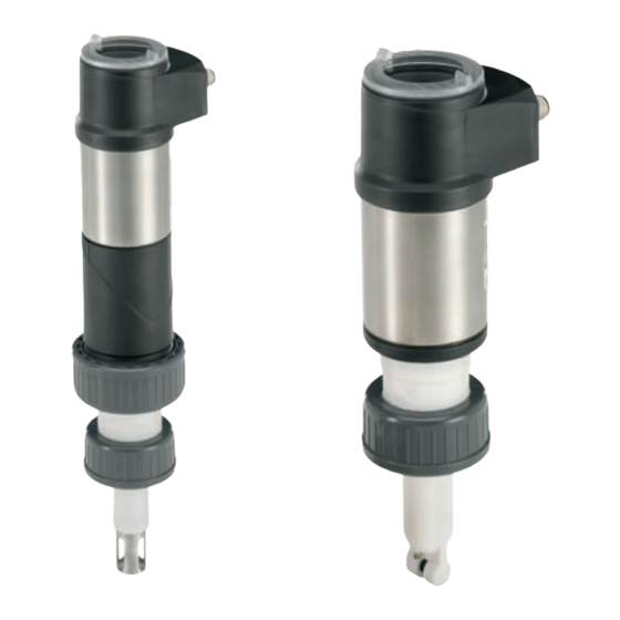
Type 8202 ELEMENT Description dEscRipTioN 5.1. Area of application The 8202 transmitter is intended solely for the measurement of: • the pH in clean liquids or liquids containing solids, sulphides or proteins. • or the oxidation reduction potential in clean liquids or liquids containing solids, sulphides or proteins which may present low conductivity. Thanks to two fully adjustable transistor outputs, the transmitter can be used to switch a solenoid valve, activate an alarm and, thanks to one or two 4-20-mA current outputs, establish one or two control loops. 5.2. General description 5.2.1. design The 8202 transmitter comprises: • a module for measuring process values, comprising: - a pH or Redox sensor measuring a potential difference (PD) in mV - a Pt1000 temperature sensor built in the holder of the pH or Redox sensor, measuring a resistance. • an acquisition / conversion module for the process values measured: - measured PD acquisition in mV - conversion of the measured PD into pH units (for a transmitter with pH sensor only) - acquisition of the resistance measured and conversion into temperature • a display module with browse button used to read and/or configure the parameters of the device. The display module is available as an accessory. -
Page 13: Description Of The Name Plate
Type 8202 ELEMENT Description 5.3. description of the name plate 1. Type of transmitter and parameter measured 8202 pH/ORP Transmitter Supply: 14-36VDC 40W Max 2. Electrical power supply and power consumption Output: 1x4-20mA 2xTrans 1A Max Cell:pH -2/16 ORP +-2000mV 120mm PG13.5 3. Output specifications Process: Temp 0/50°C limited by cell PN 16 Bar limited by cell 4. Sensor specifications... -
Page 14: Technical Data
Type 8202 ELEMENT Technicaldata TEchNicAL dATA 6.1. conditions of use Ambient temperature -10 to +60 °C (without pH or Redox probe) Air humidity < 85 %, non condensated Protection rating IP65 and IP67 with connectors plugged in and tightened and electronic module cover fully screwed down 6.2. conformity to standards and directives The device conforms to the CE directives through the following standards: • EMC: EN 61000-6-2, EN 61000-6-3 • Vibration: EN 60068-2-6 • Shock: EN 60068-2-27 • Pressure: complying with article 3 of §3 from 97/23/CE directive. Acc. to the 97/23/CE pressure directive, the device can only be used in the following cases (depending on max. pressure, pipe diameter and fluid): type of fluid conditions Fluid group 1, §1.3.a only DN25 Fluid group 2, § 1.3.a ≤ or DN > 32 and PNxDN 1000 ≤... -
Page 15: General Technical Data
Type 8202 ELEMENT Technicaldata 6.3. General technical data 6.3.1. Mechanical data • A: application range of a 8202 with a PVDF nut P (psi) P (bar) • B: application range of a 8202 with a PVC nut 217.6 PVDF The measures have been made at an ambient 188.6 temperature of 60 °C 159.6 130.6 P = Fluid pressure 101.6 PVDF T = Fluid temperature 72.5 43.5 +100... - Page 16 Type 8202 ELEMENT Technicaldata part material Box / seals stainless steel, PPS / EPDM EPDM Nickel-plated brass Cover / seal PC / EPDM Display module PC / PBT Stainless steel EPDM M12 fixed connector nickel-plated brass Fixed connector holder stainless steel 1.4404 (316L) Screws stainless steel PVC or PVDF Sensor holder / seal (in PVDF, stainless steel 1.4571 contact with the fluid) (316Ti) / EPDM EPDM pH/Redox probe pH or Redox probe refer to the related manual PVDF PVC or PVDF PVDF Stainless steel 316Ti Fig. 5 Materials used in the transmitter 8202 (without the probe) 23.8...
-
Page 17: General Technical Data
Type 8202 ELEMENT Technicaldata 6.3.2. General technical data Pipe diameter DN25 to DN110 (DN15 to DN20 under specific conditions) Type of fitting Adapter S022 Nut between the 8202 and the fitting G 1 1/2'' internal thread max. fluid temperature The fluid temperature may be restricted by the probe used (see the related instruction manual), by the pressure of the fluid and the material of the adapter S022 • with a PVDF nut (see also Fig. 2and Fig. 4) • -20 to +130 °C • 0 to +50 °C • with a PVC nut (see also Fig. 2 and Fig. 3) Max. fluid pressure PN16 The fluid pressure may be restricted by the probe used (see the related instruction manual), by the temperature of the fluid and the material of the adapter S022 (see Fig. 2, Fig. 3 and Fig. 4) ph measurement • -2 to 16 pH or -580 to +580 mV • Measurement range • 0.001 pH or 0.1 mV • Resolution... -
Page 18: Electrical Data
Type 8202 ELEMENT Technicaldata 6.3.3. Electrical data power supply • Version with 3 outputs • 14-36 V DC, filtered and regulated • Version with 4 outputs • 12-36 V DC, filtered and regulated Characteristics of the power source (not supplied) of • limited energy source (in accordance to UL 61010-1, the UL versions paragraph 9.3) • or Class 2 source (in accordance to standards 1310/1585 and 60950-1) current consumption • Version with 3 outputs • 25 mA max. (at 14 V DC) • 5 mA max. (at 12 V DC) • Version with 4 outputs Current consumption, with loads on the transistors 1 A max. Power consumption 40 W max. Protection against polarity reversal Protection against voltage spikes yes, transistor outputs... -
Page 19: Ph/Redox Probe
Type 8202 ELEMENT Technicaldata number of fixed connectors type of connectors 1 male M12 fixed connector and 1 female 5-pin female M12 connector (not supplied) and 5-pin male M12 M12 fixed connector connector (not supplied). For the M12 connector with order code 917116, use a shielded cable: • diameter: 3 to 6.5 mm • wire cross section: max. 0.75 mm 6.3.5. ph/Redox probe The pH or redox probe must satisfies the following specifications: • combined probe; • length: 120 mm; • with PG 13.5 head; • with an S7/S8 fixed connector; • without temperature probe. The specifications of the probe can be found in the manual of the probe used. English... -
Page 20: Assembly
Type 8202 ELEMENT Assembly AssEMbLy 7.1. safety instructions WarnIng Risk of injury due to non-conforming assembly. • The device must only be assembled by qualified and skilled staff with the appropriate tools. Risk of injury due to unintentional switch on of power supply or uncontrolled restarting of the installation. • Avoid unintentional activation of the installation. • Guarantee a set or controlled restarting of the process subsequent to any intervention on the device. 7.2. unscrewing the cover nOTe the tightness of the transmitter is not guaranteed when the cover is removed. • Prevent the projection of liquid inside the housing. the transmitter may be damaged if a metal component comes into contact with the electronics. • Prevent contact of the electronics with a metal component (screwdriver, for example). → To unscrew the cover, use your hand or a tool which can be used as a lever, taking care not to scratch the glass. → Turn the cover until fully unscrewed. Fig. 7 Unscrewing the cover English... -
Page 21: Mounting The Cover
Type 8202 ELEMENT Assembly 7.3. Mounting the cover → Check that there is a seal on the cover and that it is not damaged. Replace it if necessary. → Grease the seal if necessary, using a component compatible with the seal material. → Fully tighten by hand to guarantee tightness. Fig. 8 Fitting the cover 7.4. Mounting the display module → Unscrew the cover (see chapter 7.2). 20° → Set the display module at an angle of ca. 20° in relation to the desired position. → The module can be mounted in 4 different positions, at 90° intervals. → Fully push in the module and turn to the right to lock it. Fig. 9 Mounting the display module... -
Page 22: Removing The Display Module
Type 8202 ELEMENT Assembly 7.5. Removing the display module → Unscrew the cover if necessary (see chapter 7.2). → Turn the module by ca. 20° to the left. Once unlocked, the module is raised slightly by the spring action. 20° → Remove the module from its housing. Fig. 10 Removing the display module 7.6. Mounting the probe into the holder (without fluid) Following instructions are valid for a Bürkert probe. probe head compression washer If you use a probe from another supplier, respect the related instructions. seal → Remove the protective plugs →... -
Page 23: Mounting The Electronic Module To The Sensor Holder (Without Fluid)
Type 8202 ELEMENT Assembly 7.7. Mounting the electronic module to the sensor holder (without fluid) → Check that the probe is mounted into the sensor holder (see chapter 7.6). → Check that seal "A" on the holder is in good condition. Replace it if necessary (see Chap. 11) → Clean connectors "B" and "C" for connection of the pH/redox probe with alcohol to avoid measurement errors. → Insert the electronic module into the holder, making sure the polarising slots are correctly positioned. →... -
Page 24: Installation And Commissioning
Type 8202 ELEMENT Installationandcommissioning iNsTALLATioN ANd coMMissioNiNG 8.1. safety instructions danger Risk of injury due to high pressure in the installation. • Stop the circulation of fluid, cut off the pressure and drain the pipe before loosening the process connections. Risk of injury due to electrical voltage. • Shut down and isolate the electrical power source before carrying out work on the system. • Observe all applicable accident protection and safety regulations for electrical equipment. Risk of injury due to high fluid temperatures. • Use safety gloves to handle the device. • Stop the circulation of fluid and drain the pipes before loosening the process connections. Risk of injury due to the nature of the fluid. • Respect the regulations on accident prevention and safety relating to the use of aggressive fluids. WarnIng Risk of injury due to non-conforming installation. • The electrical and fluid installation can only be carried out by qualified and skilled staff with the appropriate tools. • Install appropriate safety devices (correctly rated fuse and/or circuit-breaker). • Respect the assembly instructions for the fitting used. Risk of injury due to unintentional switch on of power supply or uncontrolled restarting of the installation. • Avoid unintentional activation of the installation. -
Page 25: Installation Onto The Pipe
Type 8202 ELEMENT Installationandcommissioning 8.2. installation onto the pipe danger Risk of injury due to high pressure in the installation. • Stop the circulation of fluid, cut off the pressure and drain the pipe before loosening the process connections. Risk of injury due to the nature of the fluid. • Respect the regulations on accident prevention and safety relating to the use of aggressive fluids. If a pH/redox probe (with PG 13.5 head, 120 mm long and without temperature probe) from a supplier other than Bürkert is used, follow the relevant instructions on installation in the pipe. → Choose an appropriate position in the pipe to install the fitting. → Fit the pipe with a fitting with G 1” ½ external threaded sensor connection with respect to the instructions delivered with the fitting. Direction of the fluid Fig. 13 Mounting positions in the pipe → Fit the fitting at an angle of ±75° max. to the vertical 75° 75° in order to ensure the good operation of the pH/redox probe. Fig. 14 Angle to the vertical The probe must always be immersed in the fluid to prevent it drying out. - Page 26 Type 8202 ELEMENT Installationandcommissioning → Remove the electronic module by pulling it straight out. There may be a resistance due to the seal. Fig. 15 Remove the electronic module from the sensor holder → Install the holder with its probe on the fitting as shown in Fig. 16. → Check the presence and the condition of seal B on the fitting. Replace the seal if necessary. → Insert the holder with its probe carefully into the fitting. → Tighten the nut on the fitting by hand. → Charge the pipe to check the tightness of the assembly. Fig. 16 Installing the sensor holder with its probe on a fitting →...
-
Page 27: Electrical Wiring
Type 8202 ELEMENT Installationandcommissioning → Check that seal "A" on the holder is in good condition. Replace it if necessary (see chap. 11 and chap. 10.4). → Insert the electronic module into the holder, making sure the polarising slots are correctly positioned. polarising slots → Apply slight vertical pressure to engage the seal. → Fasten the electronic module and the holder together by tightening the nut. Tighten the G 2'' nut by hand only, until it stops turning, to ensure good electrical contact with the temperature probe. Fig. 17 Mounting the electronic module to the sensor holder, after installation of the holder on a fitting 8.3. Electrical wiring danger Risk of injury due to electrical voltage. -
Page 28: Equipotentiality Of The Installation
Type 8202 ELEMENT Installationandcommissioning → Strip 20 mm of the cable. → Cut the central wire (earth) so that its length is equal to 11.5 mm. → Expose 5.5 mm of the wires on the stripped cable. → Insert each wire into the appropriate pin on the terminal block [5] (see chap. 8.3.3 and 8.3.4). → Tighten the terminal block [5] wired to the body [4]. → Tighten the connector nut [1]. Fig. 18 M12 multi-pin connector (not provided) 8.3.2. Equipotentiality of the installation To ensure the equipotentiality of the installation (power supply - device - medium): → Connect together the various earth spots in the installation to eliminate the potential differences that may occur between different earthes. → Observe faultless grounding of the shield of the power supply cable. → Special attention has to be paid if the device is installed on plastic pipes because there is no direct earthing possible. Proper earthing is performed by earthing together the metallic devices such as pumps or valves, that are as close as possible to the device. Power supply Fig. -
Page 29: Wiring A Version With A Single M12 Fixed Connector
Type 8202 ELEMENT Installationandcommissioning Devices such as valves, pumps,... Power supply Pipes in plastic Fig. 1 Equipotentiality skeleton diagram with pipes in plastic 8.3.3. Wiring a version with a single M12 fixed connector Transistor output 1 V+ (14-36 V DC) Transistor output 2 Fig. 20 Pin assignment of the fixed connector on a version with a single M12 fixed connector... - Page 30 Type 8202 ELEMENT Installationandcommissioning Load 1 (solenoid valve for instance) white brown black grey blue Load 2 (solenoid valve for instance) Power supply 14-36 V DC Fig. 22 PNP wiring of both transistor outputs (software setting "PNP/source", see chap. 9.11.8), of a version with 1 M12 fixed connector 4-20mA input at external 4-20mA input at external...
-
Page 31: Wiring A Version With 2 M12 Fixed Connectors
Type 8202 ELEMENT Installationandcommissioning 8.3.4. Wiring a version with 2 M12 fixed connectors Transistor output 1 Transistor output 2 (12-36 V DC) (12-36 V DC) Current output 2 Current output 1 female fixed connector male fixed connector Fig. 26 Pin assignment of the male and female M12 fixed connectors connect the power supply for the transmitter to the male fixed connector; the supply is then transferred internally to pins 1 and 3 of the female fixed connector in order to ease wiring of the load to the female fixed connector. pin of the m12 female cable available as an accessory (order code 438680) colour of the wire brown white... - Page 32 Type 8202 ELEMENT Installationandcommissioning Load 2 (solenoid valve for instance) Load 1 (solenoid valve for instance) white white brown blue grey blue Power supply 12-36 V DC Fig. 28 PNP wiring of both transistor outputs of a version with 2 fixed connectors (software setting "PNP/source", see chap. 9.11.8) 4-20mA input at external device 4-20mA input at external...
- Page 33 Type 8202 ELEMENT Installationandcommissioning Load 1 Load 2 white white blue brown brown grey black black 12-36 V DC 4-20mA input at external 4-20mA input at external device device Power supply Fig. 31 NPN wiring of both transistor outputs and wiring of both current outputs in sinking mode, on a version with 2 fixed connectors (software setting "NPN/sink", see chap.
-
Page 34: Operating And Functions
Type 8202 ELEMENT Operatingandfunctions opERATiNG ANd fuNcTioNs 9.1. safety instructions WarnIng Risk of injury due to nonconforming adjustment. Nonconforming adjustment could lead to injuries and damage the device and its surroundings. • The operators in charge of adjustment must have read and understood the contents of this manual. • In particular, observe the safety recommendations and intended use. • The device/installation must only be adjusted by suitably trained staff. 9.2. functions The device has 2 operating levels: Read level This level is used: • to read the measured values of 2 process values selected in the Parameters menu, • to read both the lowest and highest values of the chosen process value, that have been measured by the device since the latest reset (this feature is not active by default), • to reset both the lowest and highest values of the chosen process value, if the feature has been activated, • to read the current values emitted on the 4-20 mA outputs. settings level This level comprises 5 menus: Menu title Relevant icon "Param": see chap. 9.11 This is... -
Page 35: Using The Navigation Key
Type 8202 ELEMENT Operatingandfunctions 9.3. using the navigation key Symbolised by in Symbolised by in this manual this manual Symbolised by in this manual Symbolised by in this manual Symbolised by in this manual Fig. 33 Using the navigation button you want to... press..browse in Read level • next screen: • previous screen: • ...access the Settings level • ...display the Param menu for at least 2 sec., from any screen of the Read... -
Page 36: Using The Dynamic Functions
Type 8202 ELEMENT Operatingandfunctions you want to... press..browse in the dynamic functions bar (MEAS, BACK, • next function: ABORT, OK, YES, NO) • previous function: ...confirm the highlighted dynamic function ...modify a numerical value - increment the figure selected - decrement the figure selected - select the previous figure - select the next figure - allocate the "+" or "-" sign to the numerical value to the extreme left of the numerical value then until the desired sign is displayed - move the decimal point to the extreme right of the numerical value then until the decimal point is in the desired place 9.4. using the dynamic functions you want to... choose... -
Page 37: Example For The Input Of A Numerical Value
Type 8202 ELEMENT Operatingandfunctions 9.5. Example for the input of a numerical value Modify each digit of the numerical value using: to increase the digit selected, Calib.Temp Select the digit at the extreme left of to decrease the digit the numerical value selected. +0.000°C then with Select the digit at the extreme allocate the "+" right of the numerical value with or "-" sign to the numerical value with then move the decimal point MEAS ABORT OK with Dynamic functions (accessible through and ): see chap. 9.4 9.6. -
Page 38: Description Of The Display
Type 8202 ELEMENT Operatingandfunctions 9.7. description of the display 9.7.1. description of icons and LEds Green LED: shows that Yellow LED: shows that transistor 1 is switched the device is energized mV_pH 1423 mV tempc 23.8 °c Red LED: shows an error; not used see chap. 10.5 Yellow LED: shows that transis- Yellow LED: shows that transistor 2 tor 1 is switched is switched Yellow LED: shows that Red LED: shows an error; transistor 2 is switched see chap. 10.5 Fig. 34 Position of the icons and description of the LEDs The LEDs of the display module are duplicated on the electronic board that is located under the display module: these LEDs become visible when the transmitter is not equipped with the display module. -
Page 39: When Switching On The Device
Type 8202 ELEMENT Operatingandfunctions 9.7.2. When switching on the device When the device is switched on or the display module mounted on the electronic module, the display indicates the software version of the display. The display then shows the first screen in READ level: mV_pH 1423 mV tempc 23.8 °c Fig. 35 Display indications when powering on the device 9.8. Read level mV_ph First view of the Read level. 1423 mV tempc 55 °c Display of the current outputs. 18.3 mA 7.5 mA mV_ph... -
Page 40: Accessing The Settings Level
Type 8202 ELEMENT Operatingandfunctions 9.9. Accessing the settings level > 2s Param This is when the This is This is when the Any display of the when the device is be- device is be- device is be- ing parame- ing parame- tered.... tered........ -
Page 41: Menu Structure Of The Settings Level
Type 8202 ELEMENT Operatingandfunctions 9.10. Menu structure of the settings level See chap. 9.9 to access the Settings level. If an “upload” has been done with this module Param System Up/Download Download Downl. Yes/No Upload Yes/No Upload This is This is when the when the device is be- device is be- ing parame- ing parame- Date YYYY/MM/DD tered.... - Page 42 Type 8202 ELEMENT Operatingandfunctions Param Outputs HWMode sink/NPN On a version with 2 transistor outputs source/PNP This is This is when the when the device is be- device is be- ing parame- ing parame- tered.... tered............ PVar: AC1/AC2 mV_pH mV_ORP TempF TempC INPUT 4mA:...
- Page 43 Type 8202 ELEMENT Operatingandfunctions Calib Sensor Probe Calib. Temp. Auto Constant Calibration 1st point If pH probe 2nd point? Rinse 2nd point Cal.Result Probe constant Offset: INPUT INPUT Span: Calib. interval Last cal. date VALUE INPUT Interval Temperature INPUT Diagnostic System Code 0*** Confirm code 0*** Sensor Glass electrode Activate: Yes/No Impedance: READ Ref. electrode...
-
Page 44: Parameters Menu
Type 8202 ELEMENT Operatingandfunctions Test System Code 0*** Confirm code 0*** Outputs AC1: INPUT AC2: INPUT TR1: OFF/ON TR2: OFF/ON Sensor PVar: mV_pH mV_ORP TempF TempC Value: INPUT Info Error MESSAGE Warning MESSAGE Maintenance MESSAGE Smiley MESSAGE Main READ Software Versions... -
Page 45: Setting The Date And Time
Type 8202 ELEMENT Operatingandfunctions The following data can be transferred from one device to another device of the same type: • user settings in the menu PARAM (except the date, the time, the contrast level and the brightness of the display), • user settings in the menu DIAGNOSTIC, • the access codes to the menus. DOWNLOAD: transfer the data previously uploaded into the display module using the UPLOAD function. The parameters transferred are used by the device as soon as the message “Download OK” is displayed. UPLOAD: upload data from the transmitter to the display module. 9.11.2. setting the date and time See chap. 9.9 to access the Parameters menu. Param System Date YYYY/MM/DD Time HH:MM This is This is when the when the device is be- device is be-... -
Page 46: Setting The Data Displayed In The Read Level
Type 8202 ELEMENT Operatingandfunctions 9.11.5. setting the data displayed in the REAd level See chap. 9.9 to access the Parameters menu. WarnIng Risk of injury due to wrong adjustment. • Before setting the parameters for the display, choose the type of probe (see chap. 9.11.11) mounted on the transmitter. Param Line1 / Line2: Line1 / Line2: Enabled Display Disabled This is when the This is when the device is be- device is be- ing parame- ing parame- tered.... -
Page 47: Displaying The Lowest And Highest Values Measured
Type 8202 ELEMENT Operatingandfunctions 9.11.6. displaying the lowest and highest values measured See chap. 9.9 to access the Parameters menu. WarnIng Risk of injury due to wrong adjustment. • Before setting the parameters for the display, choose the type of probe (see chap. 9.11.11) mounted on the transmitter. Param Min/Max: Status: Enabled Display Disabled This is This is when the when the device is be- device is be- ing parame- ing parame- tered.... -
Page 48: Choosing The Output Wiring Mode
Type 8202 ELEMENT Operatingandfunctions 9.11.8. choosing the output wiring mode See chap. 9.9 to access the Parameters menu. HWMode source/PNP Param Outputs sink/NPN This is when the This is device is be- when the ing parame- device is be- tered.... ing parame- ....tered........ The setting has no effect on a version with one fixed connector, if the sole current output is wired. See Fig. 23. -
Page 49: Setting The Parameters Of The Transistor Outputs
Type 8202 ELEMENT Operatingandfunctions and P are the values associated with a current of 4 mA or 20 mA respectively: If P is higher than P , the signal is inverted and the range P corresponds to the range for the 20-4 mA current. Process value chosen Fig. 37 4-20 mA current depending on the process value selected FILTER: choose the level of damping for the fluctuations of the current value for each current output. Three damping levels are proposed: "slow", "fast" or "none". The damping for the current outputs is similar to the damping of the display. See Fig. 36. DIAGNOSMODE: choose to emit a current of 22 mA on the current output selected when an "error" event related to diagnostics (see chap. 9.13.2 and 9.13.3) is generated by the transmitter or allow the current output to operate normally (choose "none"). See also "If you encounter problems" in chap. 10.5. 9.11.10. setting the parameters of the transistor outputs See chap. 9.9 to access the Parameters menu. WarnIng Risk of injury due to wrong adjustment. -
Page 50: Setting The Sensor Parameters
Type 8202 ELEMENT Operatingandfunctions If the selected transistor output is linked to the "warning" event, the transistor switches as soon as such an event is generated by the transmitter. See also "If you encounter problems", at chap. 10.5 MODE: choose the operating mode for transistor output 1 or transistor output 2. See Fig. 38 and Fig. 39. LOW: enter the low switching threshold value for transistor output 1 or transistor output 2. See Fig. 38 and Fig. HIGH: enter the high switching threshold value for transistor output 1 or transistor output 2. See Fig. 38 and Fig. CONTACT: choose the type of off-position (normally open, NO, or normally closed, NC) for transistor output 1 or transistor output 2. See Fig. 38 and Fig. 39. DELAY: choose the value of the time delay prior to switching for each transistor output. Switching only occurs if one of the thresholds, high or low (functions "High" or "Low"), is exceeded for a duration longer than this time delay. The time delay before switching is applicable to both output thresholds. hysteresis operating The change of status is done when a threshold is detected (increasing measured value: threshold high (function High) to be detected; decreasing measured value: threshold low (function Low) to be detected). contact contact process value process value Low High Low High Fig. 38 Hysteresis operating NO = Normally open ; NC = Normally closed Window operating The change of status occurs whenever one of the thresholds is detected. contact contact process value process value Low High Low High Fig. -
Page 51: Calibration Menu
Type 8202 ELEMENT Operatingandfunctions Sensor Type: Param This is This is when the when the device is be- device is be- ing parame- ing parame- tered.... tered.... Mode: Symmetric ........Asymmetric Mains Fcy: 50Hz 60Hz TYPE: choose the type of sensor used, pH or Redox ("ORP" choice) MODE: choose the type of measurement, symmetrical (differential) or asymmetrical. symmetrical measurement The symmetrical measurement is a differential measurement: in this type of measurement, the stainless steel ring on the sensor holder is used as a reference. -
Page 52: Modifying The Calibration Menu Access Code
Type 8202 ELEMENT Operatingandfunctions → choose "enabled"; → validate by "OK". In practice, when the device is in Hold mode: • the icon is displayed in place of the icon; HOLD • the current emitted on each 4-20 mA output is fixed at the value of the last measurement of the process value associated with each output; • each transistor output is fixed at the status acquired at the moment the Hold function is activated; • the device is in Hold mode until the HOLD function is deactivated. To deactivate the HOLD mode: → enter the "HOLD" function; → choose "disabled"; → validate by "OK". 9.12.2. Modifying the calibration menu access code See chap. 9.9 to access the Calibration menu. Calib System Code 0***... -
Page 53: Calibrating The Sensor
Type 8202 ELEMENT Operatingandfunctions 9.12.4. calibrating the sensor danger Risk of injury due to electrical voltage • Observe all applicable accident protection and safety guidelines for electrical equipment. Risk of injury due to the nature of the fluid. • Respect the regulations on accident prevention and safety relating to the use of aggressive fluids. See chap. 9.9 to access the Calibration menu. Choose the type of probe (see chap. 9.11.11) the transmitter is fitted with before calibrating the sensor. Calib Sensor Probe CalibTemperat. Auto Constant Calibration 1st point if pH probe 2nd point? Rinse 2nd point Cal.Result Probe constant Offset: INPUT INPUT Span: Calib. interval Last cal. date VALUE INPUT Interval... - Page 54 Type 8202 ELEMENT Operatingandfunctions • In order not to interrupt the process, activate the HOLD function (see chap. 9.12.1). • Before each calibration, correctly clean the electrode with a suitable product. • In a 2-point calibration, the buffer solutions used must be at the same temperature. • Set the periodicity of calibrations in the "Interval" function in the sub-menu "Calib interval" (see previous page): each time a calibration is due, the transmitter generates a "maintenance" event and a "warning" event. 1-point calibration The 1-point calibration procedure is used for quick calibration by adjusting the offset of the measurement graph with a buffer respectively a calibration solution with a known pH (to calibrate a pH sensor: see page 54) respectively a known oxidation reduction potential (to calibrate a Redox sensor: see page 53). 2-point calibration The 2-point calibration procedure for a pH sensor is used for the precise calibration of the offset and the gradient ("span") of the sensor measurement graph. This operation requires 2 buffer solutions: in general a first solution with a pH of 7 and a second solution with a pH very close to that of the process value to be measured. See page 54. At the end of calibration of the pH sensor, two types of messages may be displayed: Possible Recommended Message "span" value "offset" value cause action → "Warning:Span/ 50 mV/pH < span < 53 mV/pH -60 mV < Offset < -35 mV Error in Use the correct offset out of the buffer buffer solution.
- Page 55 Type 8202 ELEMENT Operatingandfunctions detailed procedure for the 1-point calibration of the oxidation reduction potential sensor Calib Sensor Probe Calibration → Immerse the clean sensor in the buffer solution; if the Hold mode is deactivated, the transmitter alternately displays: • the measured potential difference of the solution • the measured temperature of the solution Calibration 465.0 mV → Enter the potential difference 475.0 mV of the reference solution (indicated on the bottle). Cal. Result The transmitter displays the calibration result. Offset:-55.60mV Probe Probe "Error: Span/ "Warning: Cal. Result offset out of Span/offset BACK BACK Save: Yes/No range"" out of range" see Table 2 for the possible cause of...
- Page 56 Type 8202 ELEMENT Operatingandfunctions detailed procedure for the 1- or 2-point calibration of the ph probe Calib Sensor Probe Calibration → Immerse the clean sensor in the first buffer solution; if the Hold mode is deacti- vated, the transmitter alternately displays: • the measured pH of the solution • the measured temperature of the solution 1st point 7.100 pH → Enter the pH of the buffer 7.000 pH solution. Do you want to calibrate a 2nd point? → Rinse the sensor. When the pH Rinse reaches the desired value, validate 6.153 pH rinsing with "OK" 25.00 °C → Immerse the clean sensor in the second buffer 2nd point solution; if the Hold mode is deactivated, the 10.03 pH transmitter alternately displays: 10.01 pH • the measured pH of the solution • the measured temperature of the solution...
-
Page 57: Entering An Offset For The Temperature Measurement
Type 8202 ELEMENT Operatingandfunctions 9.12.5. Entering an offset for the temperature measurement See chap. 9.9 to access the Calibration menu. The temperature transmitted by the Pt1000 probe may be corrected. This correction value is the temperature offset. Calib Sensor Temperature INPUT Enter the temperature offset (input limits: ±5 °C) 9.13. diagnostic menu 9.13.1. Modifying the diagnostic menu access code See chap. 9.9 to access the Diagnostic menu. Diagnostic System Code 0*** Confirm code 0*** Enter the new code Confirm the new code Default access code to the Diagnostic menu: 0000. -
Page 58: Monitoring The Fluid Temperature
Type 8202 ELEMENT Operatingandfunctions When the transmitter generates a "warning" or "error" event: → go into the "Info" menu to read the cause of the event generation. → and/or go into the "Sensor" function of the Diagnostic menu to read the impedance values for each electrode in order to identify the cause of an out of range impedance. → if necessary, clean then recalibrate the measurement probe or replace it. • The "warning" event may also be associated with one or other or both transistor outputs. See chap. 9.11.10, function "Output.TR1" or "Output.TR2". • The "error" event may also be associated with one or other or both current outputs. See chap. 9.11.9, function "Output.AC1" or "Output.AC2". • See also "If you encounter problems" at chap. 10.5 ACTIVATE: choose whether or not to activate monitoring of the impedance of the selected electrode. IMPEDANCE: read the impedance measured of the selected electrode. WARN HI: enter the impedance value above which a "warning" event is generated. WARN LO: enter the impedance value below which a "warning" event is generated. ERR HI: enter the impedance value above which an "error" event is generated. ERR LO: enter the impedance value below which an "error" event is generated. 9.13.3. Monitoring the fluid temperature See chap. 9.9 to access the Diagnostic menu. A malfunction in your process or the built-in temperature probe may be indicated either by too low or too high a fluid temperature or by an incorrect temperature measurement. The function allows for monitoring the fluid temperature and configure the behaviour of the device if the param- etered ranges are exceeded. -
Page 59: Test Menu
Type 8202 ELEMENT Operatingandfunctions → then check whether the built-in Pt1000 is working correctly by measuring a fluid with a known temperature. If the Pt1000 is faulty, return the device to Bürkert. → if the Pt1000 is not the cause of the problem, check the process. • The "warning" event may also be associated with one or other or both transistor outputs. See chap. 9.11.10, function "Output.TR1" or "Output.TR2". • The "error" event may also be associated with one or other or both current outputs. See chap. 9.11.9, function "Output.AC1" or "Output.AC2". • See also "If you encounter problems" at chap. 10.5 ACTIVATE: choose whether or not to activate monitoring of the fluid temperature. TEMPERATURE: read the fluid temperature measured in real time through the built-in Pt1000. WARN HI: enter the fluid temperature value above which a "warning" event is generated. WARN LO: enter the fluid temperature value below which a "warning" event is generated. ERR HI: enter the fluid temperature value above which an "error" event is generated. ERR LO: enter the fluid temperature value below which an "error" event is generated. 9.14. Test menu 9.14.1. Modifying the Test menu access code See chap. 9.9 to access the Test menu. Test System... -
Page 60: Checking The Outputs Behaviour
Type 8202 ELEMENT Operatingandfunctions TR2: check that transistor output 2 is working correctly by selecting the status of the transistor ("ON" or "OFF") then "OK". 9.14.3. checking the outputs behaviour See chap. 9.9 to access the Test menu. The icon is displayed in place of the icon as soon as the check for the correct working of an output has started. During the check the related output does not react according to the measured physical value. The feature allows for simulating the measurement of the process value to check if the outputs are correctly configured. Test Sensor PVar: mV_pH mV_ORP TempF TempC INPUT Value: PVAR: choose the process value to be tested. VALUE: enter a process value selected from the "PVAR" function above to check output behaviour. 9.15. information menu 9.15.1. Reading the cause of events linked to icons See chap. 9.9 to access the Info menu. -
Page 61: Reading The Software Versions
Type 8202 ELEMENT Operatingandfunctions 9.15.2. Reading the software versions See chap. 9.9 to access the Info menu. Info Software Main READ Versions READ Sensor The function allows for reading the software version ("Main") of the acquisition / conversion board for the process values and of the sensor board ("Sensor"). English... -
Page 62: Maintenance And Troubleshooting
Type 8202 ELEMENT Maintenanceandtroubleshooting MAiNTENANcE ANd TRoubLEshooTiNG 10.1. safety instructions danger Risk of injury due to high pressure in the installation. • Stop the circulation of fluid, cut off the pressure and drain the pipe before loosening the process connections. Risk of injury due to electrical voltage. • Shut down and isolate the electrical power source before carrying out work on the system. • Observe all applicable accident protection and safety regulations for electrical equipment. Risk of injury due to high fluid temperatures. • Use safety gloves to handle the device. • Stop the circulation of fluid and drain the pipes before loosening the process connections. Risk of injury due to the nature of the fluid. • Respect the regulations on accident prevention and safety relating to the use of aggressive fluids. WarnIng Risk of injury due to non-conforming maintenance. • Maintenance must only be carried out by qualified and skilled staff with the appropriate tools. • Ensure that the restart of the installation is controlled after any interventions. 10.2. cleaning of the transmitter The device can be cleaned with a cloth dampened with water or a detergent compatible with the materials the device is made of. -
Page 63: Replacing The Probe
Type 8202 ELEMENT Maintenanceandtroubleshooting 10.3. Replacing the probe danger Risk of injury due to high pressure in the installation. • Stop the circulation of fluid, cut off the pressure and drain the pipe before loosening the process connections. Risk of injury due to electrical voltage. • Shut down and isolate the electrical power source before carrying out work on the system. • Observe all applicable accident protection and safety regulations for electrical equipment. Risk of injury due to high fluid temperatures. • Use safety gloves to handle the device. • Stop the circulation of fluid and drain the pipes before loosening the process connections. Risk of injury due to the nature of the fluid. • Respect the regulations on accident prevention and safety relating to the use of aggressive fluids. nOTe the transmitter loses the ip67 and ip65 protection ratings when dismounted. • Protect the inside of the dismounted transmitter. → Remove the probe as shown below. → Unscrew the nut between the sensor holder and the electronic module. → Remove the electronic module by pulling it straight out. There may be a slight resistance due to the seal. English... -
Page 64: Replace The Seal Of The Sensor Holder
Type 8202 ELEMENT Maintenanceandtroubleshooting → Unscrew the probe using a suitable wrench. → Remove it carefully from the holder. → Clean any fluid projections on the electrical contacts on the holder. Fig. 42 Removing the probe from the holder → Fit a new probe into the holder as shown in chap. 7.6 → Charge the pipe to check that the mounting is tight. → Refit the electronic module to the holder as shown in chap. 7.7 10.4. Replace the seal of the sensor holder danger Risk of injury due to electrical voltage. -
Page 65: Troubleshooting
Type 8202 ELEMENT Maintenanceandtroubleshooting → Remove the electronic module by pulling it straight out. There may be a slight resi- stance due to the seal. → Remove the used seal "A" from the holder. → Place the new seal "A" into the groove of the holder. Fig. 43 Replacing the seal of the sensor holder → Charge the pipe to check that the mounting is tight. → Refit the electronic module to the holder as shown in Fig. 17of chap. 8.2. 10.5. Troubleshooting Red current transistor icon message dis- possible cause Recommended action output output played in the info menu → 22 mA depending "E:Sat. ORP... - Page 66 Type 8202 ELEMENT Maintenanceandtroubleshooting Red current transistor icon message dis- possible cause Recommended action output output played in the info menu → 22 mA depending "S EE User User data for the sensor Switch the power supply Read" is lost (eg. type of off then on again. thresholds sensor). → Check the sensor param- eters in all the "Sensor" menus then save them again. "S EE User Write" → If the error persists, return the device to Bürkert. → 22 mA depending "S PT Missing" The connection to the Check that the nut Pt1000 probe is lost.
- Page 67 Type 8202 ELEMENT Maintenanceandtroubleshooting Red current transistor icon message dis- possible cause Recommended action output output played in the info menu → 22 mA depending "TR EE Fact Parameter reading error. Switch the power supply Read" off then on again. thresholds → If the error persists, set the device back to the default settings (chap. 9.11.4). "TR EE User → If the error persists, return Read" the device to Bürkert. → 22 mA depending "TR EE Parameter saving error. Switch the power supply UserWrite"...
- Page 68 Type 8202 ELEMENT Maintenanceandtroubleshooting Red current transistor icon message dis- possible cause Recommended action output output played in the info menu → 22 mA depending on "E:Impedance The impedance of the Go into the "Sensor" thresholds Ref" reference electrode is function of the Diag- out of range. nostic menu to read the impedance value The message is dis- of the reference elec- played if the monitoring trode (chap. 9.13.2). of the impedance of the reference electrode → If necessary, clean has been activated, then recalibrate the depending on the measurement sensor set thresholds ERR or replace it.
- Page 69 Type 8202 ELEMENT Maintenanceandtroubleshooting Red current transistor icon message dis- possible cause Recommended action output output played in the info menu → 4-20 mA Switched + "W:Impedance The impedance of the Go into the "Sensor" Ref" reference electrode is function of the Diag- out of range. nostic menu to read the impedance value The message is dis- of the reference elec- played if the monitoring trode (chap. 9.13.2). of the impedance of the reference electrode → If necessary, clean has been activated, then recalibrate the depending on the set measurement sensor thresholds WARN LO or replace it.
- Page 70 Type 8202 ELEMENT Maintenanceandtroubleshooting Red current transistor icon message dis- possible cause Recommended action output output played in the info menu → 4-20 mA Switched "M:Calib. Date" A calibration is due. Calibrate the sensor (chap. 9.12.4). The periodicity of the cal- ibrations is set within the "INTERVAL" function of the "CALIB INTERVAL" menu (see chap. 9.12.4). If the "PVAR" function of the "Output.TR1" and/or "Output.TR2" menus is set to "warning" (see chap. 9.11.10); else, the transistor outputs are operating depending on the set thresholds. English...
-
Page 71: Spare Parts And Accessories
Type 8202 ELEMENT Sparepartsandaccessories spARE pARTs ANd AccEssoRiEs CaUTIOn Risk of injury and/or damage caused by the use of unsuitable parts. Incorrect accessories and unsuitable replacement parts may cause injuries and damage the device and the sur- rounding area. • Use only original accessories and original replacement parts from Bürkert. spare part orde code Seal in EPDM, Ø 46x2 mm, for the sensor holder 559169 Accessory order code Display module 559168 Black blank cover with EPDM seal 560948 Transparent cover with EPDM seal 561843 pH probe, 0...14 pH, 0...+80 °C, 0...6 bar, FLATRODE pH 120 mm 561025 pH probe, 0...14 pH, -10...+60 °C, 0...6 bar, LOGOTRODE pH 120 mm 427114 pH probe, 0...14 pH, 0...+130 °C, 0...6 bar, UNITRODE PLUS pH 120 mm 560376 pH probe, 0...14 pH, 0...+130 °C, 0...16 bar, CERATRODE pH 120 mm 418319 pH probe, 0...14 pH, -10...+40 °C, 0...6 bar, PLASTRODE pH 120 mm 560377 ORP probe, -2000...+2000 mV, 0...+80 °C, 0...6 bar, FLATRODE Redox 120 mm 561027 ORP probe, -2000...+2000 mV, -10...+50 °C, 0...6 bar, LOGOTRODE Redox 560379 120 mm ORP probe, -2000...+2000 mV, 0...+130 °C, 0...6 bar, UNITRODE Redox 120 mm... - Page 72 Type 8202 ELEMENT Sparepartsandaccessories sToRAGE nOTe poor storage can damage the device. • Store the device in a dry place away from dust. • Storage temperature of the device without probe: -10 to +60°C. • Storage temperature of the device with probe: refer to the instruction manual delivered with the probe used. disposAL of ThE pRoducT → Dispose of the device and its packaging in an environmentally-friendly way. nOTe damage to the environment caused by products contaminated by fluids. • Keep to the existing provisions on the subject of waste disposal and environmental protection. note: Comply with the national and/or local regulations which concern the area of waste disposal. English...
- Page 73 Type 8202 ELEMENT English...
- Page 74 Type 8202 ELEMENT English...
- Page 76 www.burkert.com...
Need help?
Do you have a question about the 8202 ELEMENT and is the answer not in the manual?
Questions and answers